
VLS9200 user guide (BW402-10009, August 2012)


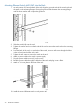


1. If the metal mounting brackets are not attached to the switch, attach them as follows:
a. Align the brackets so that the four screw holes are against the side of the switch. The side
of the bracket with two screw holes extends from the switch and aligns with the front of
the bezel.
b. Adjust alignment so that the holes in the side of the mounting bracket line up with the
holes in the switch.
c. Use a Phillips (cross-head) screwdriver and the eight M4 screws (included) to attach the
mounting brackets to the switch.
d. Attach cap nuts to the vertical posts where the mounting brackets attach to the rack.
2. Immediately above the node, on each side of the switch secure the mounting bracket to the
vertical posts with a Phillips screw.
3. Attach a power cable to the switch's power supply.
4. Route the power cable through the right side of the rack and plug it into a PDM.
5. Attach a power cable to the switch's power supply.
Cabling Ethernet Switch 2510–24
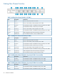
Table 9 Cabling the Ethernet Switch
Connects toDescriptionItem
NIC 3 of node via Ethernet cablePort 11
NIC 4 of node via Ethernet cablePort 22
Ethernet port of RAID controller 2 of base array enclosure via Ethernet cablePort 153
Ethernet port of RAID controller 1 of base array enclosure via Ethernet cablePort 164
1. Connect the Ethernet switch to the node using Table 9 (page 37).
2. Connect the Ethernet switch to the base array enclosure working backwards from port 16 on
the Ethernet switch.
3. Secure Ethernet cables with a Velcro® tie to the right side of the rack.
Cabling Ethernet Switch 2510–24 37