
VLS9200 user guide (BW402-10009, August 2012)
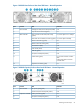


LED stateLEDLocationItem
OnPower On/OK (green)5
OnSAS Out port status (green)6
Figure 6 VLS9200 Capacity Enclosure Rear Panel LED Status – Normal Operation
LED stateLEDLocationItem
OffVoltage/Fan Fault/Service Required (amber)Power module1
OnInput Source Power Good (green)2
OffUnit Locator (white)Expansion controller3
OffOK to Remove (blue)4
OnFRU OK (green)5
OffFault/Service Required (amber)6
OnSAS In Port Status (green)7
OnSAS Out Port Status (green)8
Powering On the VLS System
To power on the system:
1. Power on the two private LAN switches connected to the VLS. (Entry-level VLS9200 systems
only include one LAN switch.)
2. Power on the two private Fibre Channel switches connected to the VLS. (Entry-level VLS9200
systems do not include Fibre Channel switches.)
3. Power on all arrays in the VLS. See “Powering on VLS Arrays” (page 89).
4. Press the Power On/Standby button on all of the secondary nodes.
5. After the secondary nodes are powering up, press the Power On/Standby button on the
primary node.
6. Confirm that the VLS components are all functioning normally and the VLS is cabled correctly
by observing their status LEDs.
The LED status should match those shown in the following table. If it does not, a component
needs attention.
92 Operation