HP VMA SAN Gateway Installation and Configuration Guide For release G5.5.
LEGAL NOTICES Copyright 2011, 2012 Hewlett-Packard Development Company, L.P. The information contained herein is subject to change without notice. The only warranties for HP products and services are set forth in the express warranty statements accompanying such products and services. Nothing herein should be construed as constituting an additional warranty. HP shall not be liable for technical or editorial errors or omissions contained herein. Copyright © 2010-2012 Violin Memory, Inc. All rights reserved.
OTHERWISE), FOR ANY DIRECT, INDIRECT, PUNITIVE, INCIDENTAL, RELIANCE, SPECIAL, EXEMPLARY OR CONSEQUENTIAL DAMAGES, INCLUDING WITHOUT LIMITATION, ANY LOSS OF DATA, LOSS OR INTERRUPTION OF USE, COST OF PROCURING SUBSTITUTE TECHNOLOGIES, GOODS OR SERVICES, OR LOSS OF BUSINESS, REVENUES, PROFITS OR GOODWILL, EVEN IF ADVISED OF THE POSSIBILITY OF SUCH DAMAGES. Violin Memory, Inc. 685 Clyde Avenue Mountain View, CA 94043USA Compliance notices and information can be found in Compliance Information on page 12.
HP VMA SAN Gateway Installation and Configuration Guide AM456-9025A
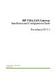
Contents Preface . . . . . . . . . . . . . . . . . . . . . . . . . . . . . . . . . . . . . . . . . . . . . . . . . . . . . . . . . . . . . . . . . . . . . . . . . . . . . . . 6 CHAPTER 1. HP VMA SAN Gateway Hardware Installation . . . . . . . . . . . . . . . . . . . . . . . . . . . . . . . . . . 10 System Specifications . . . . . . . . . . . . . . . . . . . . . . . . . . . . . . . . . . . . . . . . . . . . . . . . . . . . . . . . . . . . 10 Planning a Configuration . . . . . . . . . . . . . . . . . . . . .
Both Nodes Running G5.1.0 . . . . . . . . . . . . . . . . . . . . . . . . . . . . . . . . . . . . . . . . . . . . . . . . . . . . . . . . . . . . . 41 G5.1.0 on mg-b and G5.2.0 or Higher on mg-a . . . . . . . . . . . . . . . . . . . . . . . . . . . . . . . . . . . . . . . . . . . . . . . 41 Both Nodes Running G5.2.0 or Higher . . . . . . . . . . . . . . . . . . . . . . . . . . . . . . . . . . . . . . . . . . . . . . . . . . . . . 41 CHAPTER 5. Block Storage Configuration . . . . . . . . . . . . . . . . . .
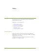
Preface This guide describes how to safely install and configure the HP VMA SAN Gateway hardware and software. This preface covers the following topics: • Intended Audience on page 6 • Document Conventions on page 7 • Reference Documents on page 8 • Getting Help on page 8 • Comments & Questions on page 9 Intended Audience This guide is intended for experienced network and system administrators.
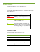
Document Conventions This documentation follows the conventions outlined in this section. Important Information The following table summarizes the notations used to call out important information, such as warning, caution, and note Safety Icons Icon Sample Text WARNING! Only authorized, qualified, and trained personnel WARNING! should attempt to work on this equipment. Caution: Caution: Follow the listed safety precautions when working on the HP VMA Array.
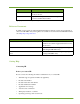
Format Meaning | Separates a set of command choices from which only one may be chosen. { } Required command parameters that must be specified are enclosed within curly brackets. Typographical Conventions (continued) Reference Documents In addition to this guide, the following Hewlett-Packard documents comprise the documentation suite for the HP VMA Array. These guides are available for download from the HP VMA manual site at http://hp.com/go/vma-docs This document... Provides this information...
HP contact information For the name of the nearest HP authorized reseller: • In the United States, see the HP US service locator webpage (http://welcome.hp.com/country/ us/en/wwcontact.html). • In other locations, see the Contact HP worldwide (in English) webpage (http:// welcome.hp.com/country/us/en/contact_us.html). For HP technical support: • In the United States, for contact options see the Contact HP United States webpage (http:// welcome.hp.com/country/us/en/contact_us.html).
CHAPTER 1 HP VMA SAN Gateway Hardware Installation This chapter covers the HP VMA SAN Gateway hardware deployment in the following topics. • • System Specifications on page 10 Planning a Configuration on page 10 System Specifications Review the system specifications as described in System Specifications on page 65 to create a deployment plan that meets the requirements for your site.
Defining a Configuration By the time you are ready to install the HP VMA SAN Gateways, the type of configuration to be implemented should have already been decided upon: • Standalone • Redundant Gateway pair for High Availability access If this decision has not yet been reached, review the System Configuration Examples in this chapter to define the configuration best suited for your site. Then review the and acquire the necessary items.
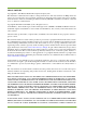
Single HP VMA SAN Gateway with 1–2 HP VMA-series Memory Arrays, Non Redundant Figure 1.1 shows a configuration of a single VMA-series SAN Gateway is directly connected to a group of up to two HP VMA-series Memory Arrays using PCIe cables. The HP VMA SAN Gateway must be connected to Port 1 on each Memory Array in x8 mode. Figure 1.
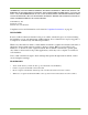
Gateway 1 is connected to Port A on Memory Array 1, then PCIe Slot 1 on SAN Gateway 2 must be connected to Port B on Memory Array 1. Figure 1.2 Redundant gateway pair of VMA-series SAN Gateways with 2 HP VMA-series Memory Arrays, Highly Available The gigabit interfaces on each SAN Gateway, eth1 and eth2, are configured as a bonded interface (where two interfaces act as one), eth0. HA configurations require that the management traffic and cluster traffic both share the same physical links.
AM456-9025A HP VMA SAN Gateway Installation and Configuration Guide 15
HP VMA SAN Gateway Installation and Configuration Guide AM456-9025A
CHAPTER 2 Software Setup and Configuration This chapter covers the initial software setup for the HP VMA SAN Gateway, and covers the following topics: • • • • • • • • Setup Task Map on page 15 Requirements Checklist on page 16 Defining the Configuration Type on page 18 Configuring Nodes with the Setup Wizard on page 21 Saving a Configuration on page 28 Modifying an Existing Configuration on page 28 Verifying vSHARE and Other Licenses on page 29 Verifying Storage Media on page 30 Setup Task Map HP VMA SA
Requirements Checklist Before you begin the installation process, it is important that you have the necessary materials on hand and have met the other requirements on the following checklist: Requirement Laptop computer with terminal emulation software Notes PuTTY or similar emulation application Appropriate serial cables for the Memory Array and San Gateway Network cable to attach between your laptop and a node, if necessary USB to serial converter to connect the serial cable to your laptop The appropr
Gather the following information for each SAN Gateway node in preparation for the setup wizard.
Information Notes Cluster Management IP Address (VIP for MG cluster access for redundant gateways.) Cluster Management IP Netmask Cluster Expected Nodes (Initially "1". Change the value after following instructions in the Redundant Gateway Pairing Process Guide.) Table 2.2 Software Configuration Checklist Defining the Configuration Type Before you begin the configuration process, you should have defined a configuration type and be familiar with its parameters.
All global cluster parameters are defined on the master node, and are automatically inherited by additional nodes as they are added to a cluster. The following chart lists the master or standalone node parameters for which the configuration wizard prompts you. Public interface name This specifies the Ethernet port that is used for specific gateway management. If only a single Ethernet cable will be used to connect the Gateway node, then eth1 should be used.
Cluster expected nodes Set the number of nodes (HP VMA SAN Gateways) in the cluster to "1". Change the value as in instructed in the Redundant Gateway Pairing Process Guide. Note: This is the expected number of HP VMA SAN Gateway nodes only. Do not include the number of HP VMA-series Arrays. Cluster ID The cluster id can be found in the login banner. The default is its preset value. This id should be changed for redundant gateway configurations.
Global default gateway Enable or disable. The Global Default Gateway is set and used for the cluster. It is recommended that you enable the global default gateway. DNS server name(s) Specify a primary and, optionally, a secondary DNS server. DNS Domain name The name of your local domain. Hostname A local hostname for the HP VMA SAN Gateway. Admin password Setting a password is highly recommended. Timezone Set the clock timezone by specifying the zone and subzones.
Logging in to the SAN Gateway The configuration process is done through a locally connected KVM setup or a terminal emulator window (such as PuTTY) connection to the SAN Gateway node. To log in to the SAN Gateway node, do the following: 1. Launch a terminal window, enter the host name or IP address of the SAN Gateway node in the appropriate text field, and open. The following example shows a PuTTY launch dialog. A terminal window appears, or use a KVM setup locally connected to the gateway. 2.
How to Get Help During the Configuration The configuration displays information on how to get help at the beginning of the wizard script, as shown in the following example: Violin Memory Gateway configuration wizard Press '?' for help, Ctrl+B to go back to the previous step. Default value is in square brackets: press Enter to accept it. Press Ctrl+R to clear default to enter empty string. Press Ctrl+C to jump to the end of the wizard at any time. To get help with the current step in the wizard, enter "?".
The fastest way to configure a master or standalone HP VMA SAN Gateway node is with the setup configuration wizard. Note: Interface bonding and cluster VLAN configuration are not included in the configuration wizard setup. For initial cluster setup, or for single-Ethernet cable to Gateway configurations, you can specify the eth1 interface as the “Public interface name” and “Cluster interface name” in the wizard.
4. Enter a value or press the Enter key to accept the default value shown in square brackets (if one is present). Step Step Step Step Step Step Step Step Step Step Step Step Step Step Step Step Step Step Step Step Step Step Step 2: Public interface name? [eth1] 3: Public interface IP address? [10.1.14.200] 4: Public interface netmask? [255.255.252.0] 5: Global default gateway? [10.1.12.1] 6: DNS server name(s)? [10.1.12.5] 7: Domain name? [my.storageco.
The configuration wizard displays the HP VMA SAN Gateway cluster settings, as shown in the following example, then exits to the CLI. You have entered the following information: 1. Configure as master/stand-alone: yes 2. Public interface name: eth1 3. Public interface IP address: 10.1.14.200 4. Public interface netmask: 255.255.252.0 5. Global default gateway: 10.1.12.1 6. DNS server name(s): 10.1.12.5 7. Domain name: my.storageco.int 8. Hostname: my-gateway1 9. Set clock timezone: yes 10.
Configuring a Secondary HP VMA SAN Gateway Node Configuring a secondary SAN Gateway node is similar to configuring an additional node in a SAN Gateway cluster (a standby or normal node). Note: If you are configuring an additional node in a cluster, you should have successfully completed the procedure described in Configuring a HP VMA SAN Gateway Master/Standalone Node on page 23. • Standby node: The second node added to the cluster is automatically designated as the secondary node.
Saving a Configuration You can save configuration parameters to persistent storage in the active configuration file from the CLI using the configuration write command, as shown in the following example. gateway02 [cluster1: master] (config) # configuration write Note: It is recommended that you save the current configuration before making any modifications to the configuration. This provides a backup configuration file, in case you want to revert to previous settings.
The following table lists the recommended software and settings for optimum performance of the VMA Gateway Web Interface. Recommendation Description Display resolution The minimum recommended display resolution for the VMA Web Interface is 1024 by 768 pixels. JavaScript JavaScript must be enabled for the VMA Gateway Web Interface. Adobe Flash Player Adobe Flash Player version 8 (or above) is required for viewing charts in the VMA Gateway Web Interface.
2. Enter the following command. # show license Output similar to the following appears: License 1: LK2-VSHARE-XXXX-XXXX-XXXX-XXXX-XXXX-XXXX Feature: VSHARE Valid: yes Tied to cluster ID: 99999 (ok) Active: yes License 2: LK2-RESTRICTED_CMDS-XXXX-XXXX-XXXX-XXXX-XXXX-XXXX Feature: RESTRICTED_CMDS Valid: yes Tied to cluster ID: 99999 (ok) Active: yes Note: If an installed license shows "no" as the Active output, an error may have been made when inputting the license key.
CHAPTER 3 VMA SAN Gateway Management and Configuration This chapter covers VMA SAN Gateway configuration and management tasks and includes the following topics: • • • • • VMA SAN Gateway Management Overview on page 31 Prerequisites on page 32 Configuring Interface Bonding on page 32 Gateway Network Configuration Guidelines on page 36 Managing a Redundant Gateway Pair on page 37 VMA SAN Gateway Management Overview You can group together redundant HP VMA SAN Gateway pairs and connected HP VMA-series Array
Note: At any one time, there can only be one active master node and one standby node in a cluster. Prerequisites You should have already successfully completed the following tasks. • Configured the master HP VMA SAN Gateway node, defining the global cluster parameters in the process. • Set up HP VMA-series Memory Array nodes, as described in the HP VMA-series Memory Array Installation and Service Guide.
• When using LACP, ensure that all network switches are LACP-enabled. Depending on the switch’s capabilities and configuration, the port LACP settings may be either active or passive. Active mode is recommended, because only aggregated traffic is expected from the HP VMA SAN Gateway. For more information, see the HP VMA SAN Gateway User’s Guide. Interface Bonding Example There are many types of bonding modes available, some of which require changing network switch settings.
2. Log in as admin. 3. Enter enable mode, and then configure terminal with the following commands. > enable # configure terminal 4. (config) (config) (config) (config) # # # # Enable bonding using the following commands: network bond eth0 interface eth1 interface eth2 mode balance-rr cluster interface eth0 cluster master interface eth0 wr mem 5. Repeat steps 1 through 4 on the secondary node. 6. Reboot both HP VMA SAN Gateway nodes to reconnect the cluster.
Gateway Management Network Configuration You must configure network switches and network connections for the cluster nodes, so that the master and secondary nodes in a management group can communicate with each other.
Defining Additional Parameters Set the following parameters via the serial console port on the Master SAN Gateway, or via the management VIP address: • Global network parameters: Default Gateway or DNS Server information. • NTP Server IP address for time synchronization. • SMTP Server IP address for email configuration. • Private VLAN for communication between redundant gateway pairs.
Management VLAN Configuration The VMA-series SAN Gateway can use a separate network for low-latency, low-bandwidth communication between HP VMA SAN Gateways in a cluster. To separate redundant gateway network traffic from management traffic, you can configure a virtual local area network (VLAN). Network switches must also be configured to provide a private VLAN if it will be used for the cluster network traffic.
Configuration File Management Changes made to the configuration of a HP VMA SAN Gateway redundant pair take effect immediately. Those changes can be lost if they are not saved to a configuration file, however. The HP VMA SAN Gateway redundant pair stores one or more configuration files on persistent storage, one of which is designated as the active configuration file. The active configuration file is where configuration changes are stored when you save a configuration.
CHAPTER 4 VMA Gateway Node Replacement This chapter demonstrates how to replace a HP VMA SAN Gateway node in a redundant pair, and covers the following topics: • Prerequisites on page 39 • Procedure Steps on page 40 • Completing the Replacement on page 41 Prerequisites A typical VMA gateway configuration consists of one or two HP VMA SAN Gateways, one of which is designated as the master node (mg-b) and one which is designated as the secondary node (mg-a).
Gather the following information before you begin the procedure to replace the gateway node (mga): • Existing cluster ID (for the master node mg-b) • Static IP address for master node mg-b • Static IP address for node mg-a being replaced • Netmask for node mg-a being replaced Procedure Steps Use this procedure to power down and remove a VMA Gateway node from a redundant gateway, then configure a replacement VMA Gateway node.
Completing the Replacement Go to the section that represents your configuration, and follow the steps to complete the replacement: • Both Nodes Running G5.1.0 on page 41 • G5.1.0 on mg-b and G5.2.0 or Higher on mg-a on page 41 • Both Nodes Running G5.2.0 or Higher on page 41 Both Nodes Running G5.1.0 If both your existing Memory Gateway node (mg-b) and the newly replaced Gateway node are both running software version G5.1.0, complete the following steps: 1.
3. Log in to mg-b as admin, and enter the following command after the prompt: mg-b [violin: master]# fms admit The following is an example of the resulting output. The exact values will depend on your configuration. Found 1 FRU Module(s) applying for cluster membership: 1) Module ID: 1ededc96b4c6, Internal Address 169.254.181.61 Please make a selection from the above list to admit it to the cluster. 4. Enter the number of the node you want to admit into the cluster. In this example, the choice is 1.
d. The state displayed on the command line prompt changes to "standby". 8.
HP VMA SAN Gateway Installation and Configuration Guide AM456-9025A
CHAPTER 5 Block Storage Configuration This chapter describes vSHARE, its features and functions, and the steps required to configure the HP VMA SAN Gateway to manage block storage.
• Initiators and Initiator groups: An initiator is a host or client that requires access to the LUNs stored in the containers. Multiple initiators may be grouped together in an initiator group (igroup). Access to the LUNs in a container may be restricted to specific initiators or initiator groups. • Targets: A target identifies the port on the HP VMA SAN Gateway through which the initiator may access the LUNs stored in a container. Access to the LUNs in a container may be restricted by target port.
Configuration Overview Configuring vSHARE is a prerequisite to using a HP VMA SAN Gateway for block storage. The vSHARE configuration allows you to define sophisticated rules for controlling access to the LUNs by initiator groups, initiators, or target ports. Configuring target ports and initiator groups are optional steps in the vSHARE configuration process. Organizations that do not want to use LUN-masking can control access to LUNs through ports or switches.
Configuring Storage Containers The first step in configuring a vSHARE HP VMA SAN Gateway is to format the HP VMA-series Arrays and create the containers needed to manage LUNs in the target storage on each Memory Array. LUNs are addressable subsets of the container in a Memory Array. When a LUN is created, it is assigned to a specific container and inherits the attributes of that container. Note: As of this release, one container comprises a HP VMA-series Array.
Configuring Block Storage This section demonstrates how to use the media init command to initialize a HP VMA-series Array connected to a VMA Gateway for block storage. To initialize the HP VMA-series Array for block storage, complete the following steps: 1. Connect to the HP VMA SAN Gateway through a terminal port, such as PuTTY. 2. Enter Configure mode, using the following commands. > enable # configure terminal (config) # 3. Enter the media init command to initialize the HP VMA-series Array.
To view existing containers, complete the following steps: 1. Log in as an administrator to the VMA Gateway attached to Port 1 of the HP VMA-series Array. 2. Use the configure terminal command to enter Configure mode. # configure terminal (config) # 3. Enter the media block id all enable command to enable all block containers. (config) # media (config) # media block id all enable The block parameter ensures that you enable vSHARE devices.
Every target is a specific port on a hardware Fibre Channel host bus adapter (HBA) installed in the gateway. For Fibre Channel, the target ports are present when the HP VMA SAN Gateway boots. A LUN may be exported through multiple target ports. Active-active multipathing is supported. Configuring Fibre Channel Target Ports For Fibre Channel, the target ports are present when the HP VMA SAN Gateway boots, if the HBAs are installed on the system.
Parameters [node ] Displays targets on node ID. [hostname ] Displays targets on hostname. [protocol fc] Displays targets using protocols. [id ] Displays a specific target. [sessions] Displays targets including sessions. [detail] Displays in detail. Configuring Initiator Groups The third step in configuring the VMA SAN Gateway is to configure the initiator groups (igroups), which identify the initiators (hosts) that are allowed to access a LUN or set of LUNs.
Fibre Channel initiator identifiers (WWN) are fixed by the HBA port. If you want to restrict LUN access to a particular initiator, you must get the appropriate the WWN from the Fibre Channel HBAs on the client machine. 4. To verify that the initiators were added to the initiator group, return to the CLI and enter the show igroups command. (config) # exit # show igroups Initiator group: #Initiators: 2 wwn.21:00:00:1b:32:9a:18:65 wwn.
igroup addto Command The igroup addto command adds one or more initiators to a group. Syntax [no] igroup addto initiators [initiator_name …] igroup_name The name is alphanumeric only. initiator_name The initiator_name must be prefixed with “wwn.” The following command adds three initiators to the initiator group named FINANCE: igroup addto FINANCE initiators wwn.20:20:20:20:20:20:20:20 wwn.20:20:20:20:20:20:20:21 wwn.20:20:20:20:20:20:20:22 The following command removes the initiator wwn.
1. From the CLI, enter into Enable mode using the enable command and then Configure mode using the configure terminal command. > enable # configure terminal (config) # 2. All LUNs are created and managed within a container. To view the available containers, use the show containers command. > enable # configure terminal (config) # show containers Check the size of the containers. LUNs are implemented in 1 GB increments; the size of the container may restrict the number of LUNs that may be created. 3.
size Defines the size of each LUN in GB, or "equal" to divide the free space of the container equally among the new LUNs. A value of 0 (zero) may be used in place of "equal." container Identifies the name of the container in which the LUN is created. quantity Defines the number of LUNs to be created; the default is 1. If the number is greater than 1, the names of the newly created LUNs will be appended with an index number from startnum up to the number of LUNs created.
Syntax Description container Displays only the LUNs within a specific container. name Displays a specific LUN. count Displays LUNs with active sessions and their count. reserved Displays LUNs with SCSI reservations. serial Displays the serial numbers for each LUN. sessions Displays the sessions accessing a particular LUN. show containers Command The show containers command displays all available containers.
lun export Command The lun export command enables you to export the LUNs within a specific container to an initiator or initiator group. A single LUN may be exported multiple times through different target ports (multipathing) or to different initiators (shared access). Syntax [no] lun export container name [lunid][to ]...
To ensure a proper MPIO operation, complete the following steps: 1. Install SP1 on Windows Server 2008 R2. 2. Install HotFix KB2522766 (from the Microsoft Support site). 3. Install HotFix KB2460971 (from the Microsoft Support site). 4. Install Hotfix KB2468345 (see the Microsoft Support site) 5. Install Hotfix KB2531907 (see the Microsoft Support site) 6. Install Hotfix KB2591462 (see the Microsoft Support site). To change the load balance policy setting, complete the following steps: 1.
The show containers command indicates that the status of the container is Single and displays the number and hostname of the Gateway for the online port.
CHAPTER 6 Multipath Client-Side Configuration This chapter provides examples of client-side multipath setup for the HP VMA SAN Gateway. The following topics are covered: • Multipath Overview on page 60 • Multipath Setup on page 61 Note: The examples in this chapter are guidelines for (client-side) Red Hat Enterprise Linux 5.x DM Multipath. For more information, go to the Red Hat Web site: http://docs.redhat.
same, regardless of the number of paths that are associated with the LUN. Using the LUN serial number, DM Multipath can determine how many paths are associated with that particular LUN. The mechanism for getting a serial number is controlled by getuid_callout parameter, which is described in the next section. Multipath Setup This section covers setting up and configuring DM Multipath on the client side for use with HP VMA SAN Gateway provided LUNs.
Setting Up DM Multipath This section shows you how to edit the multipath.conf file (the configuration file for multipathd) then configure the multipath daemon to start when the system boots up. DM Multipath default settings are suitable for common multipath configurations. Setting up DM Multipath includes the following tasks: 1. Editing the multipath.conf File on page 62 2. Configuring the Multipath Daemon on page 64 Editing the multipath.
1. Edit the multipath.conf file, uncommenting entries, similar to the following example. The devnode_blacklist includes devices for which you do not want multipathing enabled.
In the above example, support for Memory Array devices was added. When configuring this file, pay particular attention to the following: 2.
HP VMA SAN Gateway Installation and Configuration Guide AM456-9025A
APPENDIX A System Specifications This appendix contains the system specifications for the HP VMA Array and HP VMA Array. HP VMA SAN Gateway Specifications Review the following table to plan for a deployment that meets the requirements of your site. 3000 Series Model AM456-9025A Violin Memory 3205 Violin Memory 3210 Flash Type SLC SLC Raw Capacity (GiB/GB) 5.3TB/5.7TB 10.7TB/ 11.
3000 Series Model Violin Memory 3205 Violin Memory 3210 3000 Array Enclosure Dimensions: Height: Width: Depth: Cable Management: Maximum Weight: 3RU 16.9" / 430mm 28.4" / 721mm 7" / 178mm 76lbs / 34.5kg 3000 Array Enclosure Power 800W 800W 3000 Array Enclosure Cooling 3860 BTU/hr 3860 BTU/hr Memory Gateway Dimensions: 70 Height: Width: Depth: Maximum Weight: 2RU 17.2" / 437mm 25.5" / 648mm 50lbs / 22.
3000 Series Model AM456-9025A Violin Memory 3205 Violin Memory 3210 Environmentals Inlet Temp: 0C to 35C Humidity: 5-95% (non condensing) Altitude: 10,000 feet (Derate temperature) Regulatory Safety: IEC/EN 60950, CB Certificate, UL60950-1 CAN/ CSA-C22.2 No.60950-1, CE Mark Emissions Class A: EN55022/ CISPR 22, FCC Part 15 Class A, ICES-003 Issue 4 Class A, VCCI Class A, AS/NZS CISPR22:2006 Class A, BSMI CNS 13438 Class A, Korea RRA Notice No.
HP VMA SAN Gateway Installation and Configuration Guide AM456-9025A
Compliance Information APPENDIX B This appendix contains the following compliance information for the HP VMA SAN Gateway.
Security & Compliance HP cannot be responsible for unauthorized use of equipment and will not make allowance or credit for unauthorized use or access. Compliance Information Notice Description FCC Class A Compliance "This device complies with Part 15 of the FCC Rules. Operation is subject to the following two conditions: (1) This device may not cause harmful interference, and (2) this device must accept any interference received, including interference that may cause undesired operation.
Regulatory Information For your protection, this product has been tested for conformance to various national and international regulations and standards. The scope of this regulatory testing includes electrical and mechanical safety, electromagnetic emissions, immunity, acoustics and hazardous materials. Regulatory Model Number For the purpose of regulatory compliance certifications and identification, this product is assigned a regulatory model number.
• The power supply power chord must include a grounding plug and must be plugged into grounded circuit outlets. • Use only one hand when working with powered-on electrical equipment. This helps to avoid creating a complete circuit, thus preventing electrical shock. WARNING! There is a danger of explosion if the onboard battery is installed upside down, as a result of reversed polarities.
Lithium Battery Caution WARNING! Observe the correct polarity when changing the lithium battery. There is a danger of explosion if battery is installed incorrectly. Replace only with the same or equivalent type recommended by the manufacturer. Dispose of used batteries according to the manufacturer’s instructions and local disposal requirements. Note: Switzerland: Annex 4.10 of SR 814.013 applies to batteries. Cabinet Safety Precautions WARNING! Cabinets are heavy even when empty.
Perchlorate Material - Special Handling May Apply See http://www.dtsc.ca.gov/hazardouswaste/perchlorate. This product may include a real-time clock battery or coin cell battery that may contain perchlorate and may require special handling when recycled or disposed of in California. Refer to the product user documentation to determine if this product contains batteries, and if so, the battery type(s) that are used. European Union RFI Statement This is a Class A product.
Canada RFI Statement This Class A digital apparatus complies with Canadian ICES-003. Cet appareil numérique de la classe A est conforme à la norme NMB-003 du Canada. Australia C-Tick Label Figure B.
HP VMA SAN Gateway Installation and Configuration Guide AM456-9025A
Index A admin role 38 access privileges 38 password, setting 38 B battery, lithium 72 block size, of LUNs 55 block storage media devices initializing Memory Arrays 47–48 block storage, configuring 48 BSMI statement, Taiwan 74 security 69 Config mode admin role 38 configuration files active 38 management of 38 configuration wizard 28 additional Memory Gateways 27 Master Gateway configuration 32 containers configuring 47 viewing 48 C-Tick label, Australia 74 customer support 8 D C cabinet safety 72 cautio
Fibre Channel network connectivity 36 target ports 50 G global default gateway 21 H HA mode disable for container 58 disable for LUN 58 High Availability disabling 58 Memory Gateway cluster configuration 35, 37 configure additional 27 configure cluster 27 system configurations 12 upgrade 38 monitor role 38 access privileges 38 monitor username password 38 multipath client side setup 60 configuration 62 daemon (multipathd) 64 daemon, configuring 64 device mapper 60 overview 60 setup 61 multipath.
Korea 73 monitor role 38 roles 38 setting password 38 user management 38 role admin 38 monitor 38 roles correspondence to command modes 38 roles, user 38 S safety, cabinet 72 show containters 56 show luns 55 show targets 50 Standard mode unpriv role 38 standby node 27 storage containers 47 T target definition 45 target ports configuring 49 Fibre Channel ports 50 supported 49 timezone 19, 21 U upgrade Memory Gateway 38 user management 38 privileges 38 admin role 38 AM456-9025A V VCCI statement, Japan