HP VMA-series Cable Management System – Read This First HP Part Number: A0R63-9002A Published: September 2012 Edition: 1
© Copyright 2012 Hewlett-Packard Development Company, L. P.
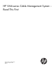
Installing the cable management brackets The Cable Management System (CMS), also called a Cable Management Arm (CMA) keeps the cables from becoming entangled when the system is fully extended from the equipment rack. The cables are routed along the length of the bracket and held in place with Velcro® cable ties. The CMA is a component added to the VMA-series chassis rack-mount option. The CMA is installed at the rear of the chassis. NOTE: The CMA is installed prior to shipping.
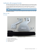
Part numbers and Descriptions A0R63-2103A HP VMA Accessory Kit Quantity: 1 675882-001 Carton, VMA accessory Quantity: 1 5992-1074 RTF Doc Quantity: 1 595851-002 CMA Quantity: 1 A0R63-2101A Bracket Kit (see image, above) Quantity: 1 A0R63-0002A Bracket CMA Rail Mount Item 1 in image, above Quantity: 1 A0R63-0001A Bracket CMA Chassis Mount Item 2 in image, above Quantity: 4 2200-1287 screw-mech 4-40 .312 _in _lg Item 3 in image, above Quantity: 6 5021-1125 Fastener, Velcro H&L 0.
2. Using the built-in captive screws, torque to 4.7 in-lb (standard for an M3 screw, as shown in Table 1). Table 1 Torque specifications MAXIMUM & MINIMUM TORQUE SPECIFICATIONS FOR ENGLISH AND METRIC SCREWS English Thread Metric Thread Minimum Torque Maximum Torque Size Major Dia. Size Major Dia. in-lb N-m in-lb N-m 2-56 .086” M2 0.079” 1.5 0.17 2.2 0.25 4-40 .112” M3 0.118” 3.3 0.37 4.7 0.53 6-32 .138” M 3.5 0.138” 6.1 0.69 8.7 0.98 8-32 .164 M4 0.157” 13 1.51 17.
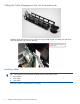
Sliding the Cable Management Arm into the bracket ends Install the cable management arm by pulling the spring loaded plunger and sliding the ends of the cable management arms into both brackets. Installing cables TIP: The manufacturer recommends installing cables in the following order: 1. Power cables 2. PCIe cables 3. LAN cables Position the cables on management arms securely.
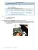
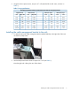
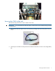
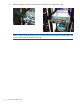
Securing the CMA to the rack Use Velcro® straps 5021-1125 to secure cables to the CMA. IMPORTANT: You must attach three Velcro® straps to each CMA to assure stability during shipment or transportation 1. Remove three Velcro® straps from the rack accessory package and remove the plastic mount, as shown: 2. Insert straps in the left rear side panel and orientate the harnesses as shown in the image below, left.
3. Adjust and tighten the straps until the CMA is horizontal. See image below, right. NOTE: Tighten the straps enough to prevent interference with movement or pinched cables, and to assure free movement of the CMA assembly.
*A0R63-9002A* Printed in the US