hewlett-packard vpn server appliance sa3110/sa3150/ sa3400/sa3450 network layout reference guide Hewlett-Packard Company HP: 5971-0873 P/N: A55307-001 March 2001
ii
Disclaimer Information in this document is provided in connection with Hewlett-Packard Company products. No license, express or implied, by estoppel or otherwise, to any intellectual property rights is granted by this document.
iv
Contents HP VPN Server Appliance SA3110/SA3150/SA3400/SA3450 Network Layout Reference Guide Network Layout Reference Guide . . . . . . . . . . . . . . . . . . . . . . . . . . . . . . . . . . . . . . . . 1 Client Scenarios . . . . . . . . . . . . . . . . . . . . . . . . . . . . . . . . . . . . . . . . . . . . . . . . . . . . . 1 LAN-to-LAN Scenarios . . . . . . . . . . . . . . . . . . . . . . . . . . . . . . . . . . . . . . . . . . . . . . . 1 Client Scenarios . . . . . . . . . . . . . . . . . . . . . . . .
HP VPN Server Appliance SA3110/SA3150/SA3400/SA3450 Network Layout Reference Guide Network Layout Reference Guide 1 The purpose of this Network Layout Reference Guide is to help you install the HP VPN Server Appliance SA3110/SA3150/ SA3400/SA3450 in your network. The term VPN device is used in this document to refer to all of these devices. Here are some real-world examples of how the VPN device can be incorporated into your network infrastructure.
HP VPN Server Appliance SA3110/SA3150/SA3400/SA3450 Network Layout Reference Guide Client Scenarios If you are using the VPN device with the HP SA3000 Series VPN Client, skim the following scenarios and find the ones most similar to your network configuration. Then, use the corresponding table of configuration parameters as a guideline when configuring your VPN device and VPN Client. If you are using the VPN device in LAN-to-LAN configurations, skip to the next section “LAN-to-LAN Scenarios.
Client Scenarios To set up a one-armed router configuration, use the configuration parameters in the following table. Note that the values of these parameters are examples only; you must enter values specific to your network. Table: One-Armed Router Configuration Parameters NAT by Router No NAT Interface E0: Interface E0: IP: 10.250.128.2 255.255.255.0 IP: 205.25.128.2 255.255.255.
HP VPN Server Appliance SA3110/SA3150/SA3400/SA3450 Network Layout Reference Guide — The VPN device then transfers the traffic on to the local network to which it is attached. The VPN device may or may not perform firewall functions on the traffic. For direct dial into the PSTN: — Traffic may go through a router or remote access server, which may or may not perform NAT. — The traffic then goes through the VPN device, which may or may not perform firewall functions on the traffic.
Client Scenarios Table: Inline Router Configuration Parameters NAT by Router No NAT Interface E0: Interface E0: IP: 10.250.128.2 255.255.255.0 IP: 205.25.128.2 255.255.255.0 Mode: Red Mode: Red In Parallel With Firewall (Extranet or Intranet) Interface E1: IP: 192.168.10.2 255.255.255.0 Mode: Red Interface E1: IP: 210.35.129.2 255.255.255.0 Mode: Red Configuration file entries/ routing info: security profile remote user remote tunnel johndoe security-profile remote user client-ip 10.250.128.3 255.
HP VPN Server Appliance SA3110/SA3150/SA3400/SA3450 Network Layout Reference Guide • — Traffic is then handed to the third-party firewall, which performs firewall functions before handing the traffic onto the local network. For direct dial into the PSTN: — Traffic may go through a router or remote access server, which may or may not perform NAT. — The traffic then goes through the VPN device (VPND), which passes the traffic to the local network.
Client Scenarios Table: In Parallel With Firewall Configuration Parameters VPN Device (NAT by Router) VPN Device (No NAT) Interface E0: Interface E0: IP: 10.250.128.2 255.255.255.0 IP: 205.25.128.2 255.255.255.0 Mode: Red Mode: Red Bridge Configuration Interface E1: IP: 192.168.10.2 255.255.255.0 Mode: Red Interface E1: IP: 210.35.129.2 255.255.255.0 Mode: Red Configuration file entries/ routing info: security profile remote user remote tunnel johndoe security-profile remote user client-ip 10.250.
HP VPN Server Appliance SA3110/SA3150/SA3400/SA3450 Network Layout Reference Guide • For direct dial into the PSTN: — Traffic may go through a router or remote access server, which may or may not perform network address translation. — The traffic then goes through the VPN device, which is set to bridge mode. The VPN device may or may not perform firewall functions on the traffic.
Client Scenarios Table: Bridge Configuration Parameters NAT by Router Inline No NAT Interface E0: Mode: Red Interface E0: Mode: Red Interface E1: Mode: Red Interface E1: Mode: Red Bridge IP: 10.250.128.2 Bridge IP: 205.25.128.2 255.255.255.
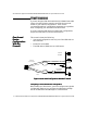
HP VPN Server Appliance SA3110/SA3150/SA3400/SA3450 Network Layout Reference Guide Internal Network Router Mode Internet Connection E1 E0 Desktop System Internet VPND With/Without Firewall Functions Laser Printer VPN Client Router or Remote Access Server No Direct Dial File Server Figure: Edge Router Configuration Configuring an Edge Router Configuration When setting up a VPN device, you must configure many global configuration settings.
Client Scenarios Behind a Firewall With or Without NAT (One-Armed) VPN Device (NAT by Router) VPN Device (No NAT) Configuration file entries/ routing info: security profile remote user remote tunnel johndoe security-profile remote user client-ip 10.250.128.3 255.255.255.255 Configuration file entries/routing info: security profile remote user remote tunnel johndoe security-profile remote user ip route 209.29.128.50 255.255.255.255 johndoe VPN Client IP: 10.250.128.
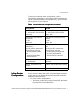
HP VPN Server Appliance SA3110/SA3150/SA3400/SA3450 Network Layout Reference Guide Internal Network A Desktop System Internal Network B (directly connected to Internet) May/May Not NAT Internet Connection Desktop System Internet Firewall Router Router Mode V P N D E 0 Laser Printer May/May Not NAT VPN Client PSTN Direct Dial Router or Remote Access Server File Server Figure: Behind a Firewall (One-Armed) Configuring a Behind a Firewall (One-Armed) Network Layout When setting up a VPN device, y
Client Scenarios Behind a Firewall With or Without NAT (Inline) VPN Device (NAT by Router) VPN Device (No NAT) Interface E1: (Not used for one-armed) IP: NA Mode: NA Interface E1: (Not used for onearmed) IP: NA Mode: NA Configuration file entries/ routing info: security profile remote user remote tunnel johndoe security-profile remote user client-ip 10.250.128.3 255.255.255.
HP VPN Server Appliance SA3110/SA3150/SA3400/SA3450 Network Layout Reference Guide — The traffic then goes through the third-party firewall, which also may or may not perform NAT before being handed to the VPN device. — The VPN device then decrypts the encrypted VPN traffic and passes it to the local network.
Client Scenarios Table: Behind a Firewall (Inline) Configuration Parameters VPN Device (NAT by Router) VPN Device (No NAT) Interface E0: Interface E0: IP: 10.250.128.2 255.255.255.0 IP: 205.25.128.2 255.255.255.0 Mode: Red Mode: Red The VPN Device as a Firewall Interface E1: IP: 192.168.10.2 255.255.255.0 Mode: Red Interface E1: IP: 210.35.129.2 255.255.255.
HP VPN Server Appliance SA3110/SA3150/SA3400/SA3450 Network Layout Reference Guide • — The VPN device then performs firewall functionality on the traffic and passes it to the local network. — The VPN device may or may not perform NAT. For direct dial into the PSTN: — Traffic may go through a router or remote access server. — The traffic then goes through firewall functionality on the VPN device. — The VPN device may or may not perform NAT before being handed onto the local network.
Client Scenarios values of these parameters are examples only; you must enter values specific to your network. Table: VPN Device as a Firewall Configuration Parameters VPN Device (NAT by Router) VPN Device (No NAT) Interface E0: Interface E0: IP: 10.250.128.2 255.255.255.0 IP: 205.25.128.2 255.255.255.0 Mode: Red Mode: Red Interface E1: IP: 192.168.10.2 255.255.255.0 Mode: Black Interface E1: IP: 210.35.129.2 255.255.255.
HP VPN Server Appliance SA3110/SA3150/SA3400/SA3450 Network Layout Reference Guide LAN-to-LAN Scenarios In Parallel With a Firewall (Without NAT) This scenario shows the following: • A LAN-to-LAN connection between two VPN devices with no NAT. • Each VPN device is attached to a router. The routers connect through the Internet. • Traffic travels from one local network, through the LAN-toLAN connection, to the other local network. • Traffic passes through the VPN device, which is in router mode.
LAN-to-LAN Scenarios Configuring an In Parallel With a Firewall (No NAT) Network Layout When setting up a VPN device, you must configure many global configuration settings. You configure the VPN device through the VPN Manager or command shell. To set up a parallel with a firewall (no NAT) configuration, use the configuration parameters in the following table. Note that the values of these parameters are examples only; you must enter values specific to your network.
HP VPN Server Appliance SA3110/SA3150/SA3400/SA3450 Network Layout Reference Guide • • • Traffic passes through the VPN device, which is in router mode. The VPN device passes the VPN traffic to the third-party firewall (in parallel with the VPN device). The third-party firewall performs firewall functionality on the traffic, then passes the traffic to the local network.
LAN-to-LAN Scenarios Table: In Parallel With a Firewall (With NAT) Configuration Parameters VPN Device A (NAT by Router) VPN Device B (NAT by Router) Interface E0: Interface E0: IP: 10.250.128.2 255.255.255.0 IP: 10.250.130.2 255.255.255.0 Mode: Red Mode: Red Behind a Firewall (OneArmed) With or Without NAT Interface E1: IP: 192.168.10.2 255.255.255.0 Default device: 192.168.10.4 Mode: Red Interface E1: IP: 192.168.12.2 255.255.255.0 Default device: 192.168.12.
HP VPN Server Appliance SA3110/SA3150/SA3400/SA3450 Network Layout Reference Guide is in front of VPN device B (which routes to the VPN device B interface for the subnet accessible through the tunnel). If you do not add this route, local machines (with their default device pointing to the firewall) will not be able to route to the VPN device A network.
LAN-to-LAN Scenarios Table: Behind a Firewall (One-Armed) With NAT Configuration Parameters VPN Device A (NAT by Router) VPN Device B (NAT by Router) Interface E0: Interface E0: IP: 10.250.128.2 255.255.255.0 IP: 10.250.135.2 255.255.255.0 Mode: Red Mode: Red Interface E1: IP: 192.168.10.2 255.255.255.0 Mode: Red Interface E1: (Not used for onearmed) IP: N/A Mode: N/A Config file entries/routing info: security-profile site-to-site tunnel SanFrancisco security-profile site-to-site route 10.250.135.
HP VPN Server Appliance SA3110/SA3150/SA3400/SA3450 Network Layout Reference Guide Table: Behind a Firewall Without NAT Behind a Firewall That May or May Not Use NAT (Inline) VPN Device A (No NAT) VPN Device B (No NAT) Interface E0: IP: 205.25.128.2 255.255.255.0 Mode: Red Interface E0: IP: 205.25.135.2 255.255.255.0 Mode: Red Interface E1: IP: 209.80.10.25 255.255.255.0 Default device: 209.80.10.
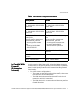
LAN-to-LAN Scenarios Desktop System Desktop System May/May Not NAT E0 E1 E1 File Server Internet VPND A Router Router Router Mode Desktop System Laser Printer E0 Desktop System Firewall VPND B Router Mode Internal Network (directly connected to Internet) Laser Printer File Server Figure: Behind a Firewall That May or May Not Use NAT (Inline) Configuring a Behind a Firewall (Inline) Network Layout When setting up a VPN device, you must configure many global configuration settings.
HP VPN Server Appliance SA3110/SA3150/SA3400/SA3450 Network Layout Reference Guide Table: Behind a Firewall wIth NAT (Inline) Configuration Parameters VPN Device A (NAT by Router) VPN Device B (NAT by Router) Interface E0: IP: 10.250.128.2 255.255.255.0 Mode: Red Interface E0: IP: 10.250.128.2 255.255.255.0 Mode: Red Interface E1: IP: 192.168.10.2 255.255.255.0 Mode: Red Interface E1: IP: 192.168.10.2 255.255.255.
LAN-to-LAN Scenarios VPN Device A (No NAT) VPN Device B (No NAT) Config file entries/routing info: security-profile site-to-site tunnel SanFrancisco ip route 210.25.129.0 255.255.255.0 205.25.128.2 Config file entries/routing info: security-profile site-to-site tunnel Boston ip route 205.35.129.0 255.255.255.0 210.25.135.2 The VPN Device as a Firewall (With or Without NAT) This scenario shows the following: • A LAN-to-LAN connection between two VPN devices.
HP VPN Server Appliance SA3110/SA3150/SA3400/SA3450 Network Layout Reference Guide Desktop System File Server Desktop System E0 E1 E1 E0 Desktop System Internet VPND A Router Router Mode Router VPND B Router Mode With Firewall Functions Enabled May/May Not NAT Desktop System May/May Not NAT Laser Printer Laser Printer File Server Figure: VPN Device as a Firewall Configuring the VPN Device as a Firewall When setting up a VPN device, you must configure many global configuration settings.
LAN-to-LAN Scenarios Table: VPN Device as a Firewall With NAT Configuration Parameters VPN Device A (NAT by Router) VPN Device B (NAT by Router) Interface E0: Interface E0: IP: 10.250.128.2 255.255.255.0 IP: 10.250.128.2 255.255.255.0 Mode: Red Mode: Red Interface E1: IP: 192.168.10.2 255.255.255.0 Mode: Red Interface E1: IP: 192.168.10.2 255.255.255.0 Mode: Red Config file entries/routing info: security-profile site-to-site site-to-site tunnel SanFrancisco security-profile site-to-site route 209.29.
HP VPN Server Appliance SA3110/SA3150/SA3400/SA3450 Network Layout Reference Guide VPN Device A (No NAT) VPN Device B (No NAT) Config file entries/routing info: security-profile site-to-site site-to-site tunnel SanFrancisco security-profile site-to-site route 209.29.128.50 255.255.255.255 Config file entries/routing info: security-profile site-to-site site-to-site tunnel SanFrancisco security-profile site-to-site route 209.29.128.50 255.255.255.0 Subnet: 205.25.128.0 (netinclude) Subnet: 205.25.128.
Inde x Index B behind a firewall inline, with or without NAT .......... 13, 24 one-armed, with or without NAT .. 11, 21 bridge configuration ................................. 7 C client scenarios................................... 2–17 behind a firewall with or without NAT (inline) ................................ 13 behind a firewall with or without NAT (onearmed) ................................ 11 bridge configuration ........................... 7 edge router configuration ...................