hewlett-packard company virtual private networking concepts guide Hewlett-Packard Company HP: 5971-3009 P/N: A55310-001 March 2001
ii
Disclaimer Information in this document is provided in connection with Hewlett-Packard Company products. No license, express or implied, by estoppel or otherwise, to any intellectual property rights is granted by this document.
iv
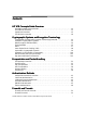
Contents HP VPN Concepts Guide Overview HP VPN Concepts Guide Overview . . . . . . . . . . . . . . . . . . . . . . . . . . . . . . . . . . . . . . . . . HP VPN Suite Overview . . . . . . . . . . . . . . . . . . . . . . . . . . . . . . . . . . . . . . . . . . . . . . . . . . . Operational Overview. . . . . . . . . . . . . . . . . . . . . . . . . . . . . . . . . . . . . . . . . . . . . . . . . . . . . TCP/IP Basics Overview. . . . . . . . . . . . . . . . . . . . . . . . . . . . . . . . . . . . . . . . . . . .
Filters . . . . . . . . . . . . . . . . . . . . . . . . . . . . . . . . . . . . . . . . . . . . . . . . . . . . . . . . . . . . . . . . . . 5-6 Tunnel Types . . . . . . . . . . . . . . . . . . . . . . . . . . . . . . . . . . . . . . . . . . . . . . . . . . . . . . . . . . . . 5-8 Site-to-Site Tunnels. . . . . . . . . . . . . . . . . . . . . . . . . . . . . . . . . . . . . . . . . . . . . . . . . . . . . . . 5-9 Single-User Tunnels . . . . . . . . . . . . . . . . . . . . . . . . . . . . . . . . . . . . . . .
HP VPN Concepts Guide Overview . . . . . . . . . . . . . . . . . . . . . . . . . . . . . . . . . . . . . . . . . 1-1 HP VPN Suite Overview . . . . . . . . . . . . . . . . . . . . . . . . . . . . . . . . . . . . . . . . . . . . . . . . . . . .1-2 Operational Overview. . . . . . . . . . . . . . . . . . . . . . . . . . . . . . . . . . . . . . . . . . . . . . . . . . . . . .1-5 TCP/IP Basics Overview. . . . . . . . . . . . . . . . . . . . . . . . . . . . . . . . . . . . . . . . . . . . . . . . . . . .
H P V PN C o n c e p t s G u i d e O v e r v i e w Hewlett-Packard Company Virtual Private Networking Concepts Guide
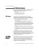
HP VPN Concepts Guide Overview 1 HP VPN Concepts Guide Overview The purpose of this HP VPN Concepts Guide is to provide you with information on the Hewlett-Packard Company virtual private networking (VPN) suite, consisting of five modular components that work together to provide secure communications across any network. The term VPN device is used in this document to refer to the HP VPN Server Appliance SA3110/SA3150/SA3400/SA3450 devices.
HP VPN Concepts Guide Overview HP VPN Suite Overview The HP virtual private networking (VPN) suite consists of three modular components that work together to provide secure communications across any network: • VPN device • HP SA3000 Series VPN Manager • HP SA3000 Series VPN Client VPN Device The VPN device is a hardware/software security system, responsible for processing data packets as they pass between the public side and the private side of a network.
HP VPN Suite Overview HP SA3000 Series VPN Client The VPN Client is a software package based in Windows 95 or Windows NT that provides desktop-to-gateway security within a LAN or across any WAN. Because all VPN devices operate at the network layer, the VPN Client is completely transparent to users and works with any application.
HP VPN Concepts Guide Overview Branch or Supplier's Office Office PCs VPN Device Server Servers (Mail, Web) VPN Manager Office PCs VPN Client Router Router VPN Client Internet Branch or Supplier's Office Office PCs Laptop Computers With modems VPN Device Router Existing Firewall Router Internet Sites Servers (Mail, Web) Figure: Typical Network Configuration Related Information Operational Overview (page 1-5) TCP/IP Basics Overview (page 1-6) HP VPN Concepts Guide Overview (page1-1) 1-4
Operational Overview Operational Overview The VPN devices fit into typical network configurations in various locations. VPN devices often sit at the gateway between LANs and WANs. All data into and out of a protected LAN passes through the VPN device for processing. The VPN Client software package runs on PCs either directly connected to a LAN or remotely located and connect to the WAN by means of a dial-up connection.
HP VPN Concepts Guide Overview TCP/IP Basics Overview The VPN devices operate on Transmission Control Protocol/ Internet Protocol (TCP/IP) networks. TCP/IP is the foundation of the Internet. To fully appreciate how the VPN devices work, you need to understand some basic TCP/IP terms. Packets and Packet Headers Communications in a TCP/IP network are broken into small chunks called packets. The typical maximum packet size carried over TCP/IP networks is 1500 bytes.
TCP/IP Basics Overview For example, "Test Company" is assigned a full class C. This means "Test Company" can use any address between 205.250.128.1 up to 205.250.128.254. The addresses 205.250.128.0 and 205.250.128.255 are also part of the addresses in the class C subnet, but are reserved for broadcasting and cannot be assigned to any devices on the network (often called boundary addresses). If you want to break your class C into separate networks, you do this by varying the last octet of the subnet mask.
HP VPN Concepts Guide Overview 192 (1100-0000) 4 62 128 (1000-0000) 2 126 0 (0000-0000) 1 254 Note: If you divide your class C into more and more subnets, the number of available addresses becomes smaller and smaller. Routing Table When a device creates a packet for transmission, it looks at the destination IP address. If the address is on the same subnet as the device (as defined by the subnet mask), the device looks for the address on its LAN.
TCP/IP Basics Overview implies that the default gateway's IP address must be on the same subnet as the originating device. Computers can directly communicate only with devices on their local subnet (as defined by their IP address and subnet mask). Default gateways are what make the Internet work. When a packet is created by a desktop computer destined for an address on the Internet, the desktop computer often sends the packet to its default gateway.
HP VPN Concepts Guide Overview Related Information HP VPN Concepts Guide Overview (page1-1) Operational Overview (page 1-5) The Template Concept 1-10 Hewlett-Packard Company Virtual Private Networking Concepts Guide
Cryptographic Systems and Encryption Terminology Overview . . . . . . . . . . . . . . . . . 2-1 Symmetric Cryptographic Systems. . . . . . . . . . . . . . . . . . . . . . . . . . . . . . . . . . . . . . . . . . .2-3 Data Encryption Standard (DES) . . . . . . . . . . . . . . . . . . . . . . . . . . . . . . . . . . . . . . . . . . . .2-4 Triple Pass DES . . . . . . . . . . . . . . . . . . . . . . . . . . . . . . . . . . . . . . . . . . . . . . . . . . . . . . . . . . .2-5 3DES . . . . . . . . . . . . . . . .
Hewlett-Packard Company Virtual Private Networking Concepts Guide C r y p t o g r a p h i c S y s t e m s a n d E n c r y p t i o n Te r mi n o l o g y
Cryptographic Systems and Encryption Terminology 2 Cryptographic Systems and Encryption Terminology Overview When Julius Caesar sent messages to his trusted acquaintances, he did not trust the messengers. So he replaced every A with a D, every B with an E, and so on throughout the alphabet. This was the beginning of cryptography. Only those who knew the "shift by 3" rule could decipher his messages.
Cryptographic Systems and Encryption Terminology In this formula, g represents a mathematical operation, which "undoes" the steps performed by the algorithm f, and Kd represents a key. Related Information Symmetric Cryptographic Systems (page 2-3) Asymmetric Cryptographic Systems (page 2-9) Symmetric Vs.
Symmetric Cryptographic Systems Symmetric Cryptographic Systems A very simple encryption algorithm involves shifting the letters of the alphabet to the right by some offset. For example if you had the clear text "AT" and decided to encrypt this data by shifting each letter 3 letters to the right, you would end up with DW. In this example, the clear text is AT, the key is 3, the algorithm is "shift K letters to the right," and the cipher text is DW.
Cryptographic Systems and Encryption Terminology Data Encryption Standard (DES) The Data Encryption Standard (DES) is a well-known and thoroughly tested cryptographic system. The DES algorithm is a very complex symmetric algorithm that specifies that data be encrypted in 64-bit blocks. A 64-bit block of clear text goes into the algorithm along with a 56-bit key. The result is a 64-bit block of cipher text.
Triple Pass DES Triple Pass DES Triple Pass DES is a cryptographic system that uses multiple passes of the DES algorithm to increase the effective key space available to the system. In triple pass DES, the clear text data is first encrypted with a 56-bit key. The resulting cipher text is then decrypted with a different key. Decrypting cipher text with the wrong key will result in unreadable data. Finally the unreadable data is encrypted again with the first key.
Cryptographic Systems and Encryption Terminology Clear Text Algorithm Related Information After First Encrypt E After First Decrypt D After Second Encrypt E Triple Pass DES (Key Space = 2*26 =52) AT K1 = 3 DW K2 = 5 YR K1 = 3 BU 3DES (Key Space = 3*26 =78) AT K1 = 3 DW K2 = 5 YR K3 = 4 CV 3DES (page 2-7) Data Encryption Standard (DES) (page 2-4) Outer Cipher Block Chaining (CBC) (page 2-8) 2-6 Hewlett-Packard Company Virtual Private Networking Concepts Guide
3DES 3DES 3DES is a symmetric cryptographic system that uses multiple passes of the DES algorithm to increase the effective key space available to the system even further than triple pass DES. Use the same EDE technique as in Triple Pass DES (page 2-5), except that 3 different keys are used. Therefore, in pass 3 of Triple Pass DES, you would select a third key (K3 = 4), which increases the effective key length from 56 bits for simple DES to 168 bits for 3DES.
Cryptographic Systems and Encryption Terminology Outer Cipher Block Chaining (CBC) Outer Cipher Block Chaining or outer-CBC is a technique used to further strengthen the DES, triple pass DES, and 3DES algorithms. This technique involves injecting random spoiler data into the encryption algorithm so that identical blocks of clear text does not result in the same cipher text even if the same key is used repeatedly.
Asymmetric Cryptographic Systems Asymmetric Cryptographic Systems Some algorithms do not use the same key to encrypt and decrypt. These algorithms are referred to as asymmetric, are usually complex, and often rely on the properties of very large prime numbers. A simple asymmetric algorithm, similar to the symmetric example, uses the same formula for encryption: DW = shift-right ( AT , 3 ) In the symmetric example the encryption was "undone" using the mathematical operation of "shift-left.
Cryptographic Systems and Encryption Terminology Symmetric Vs. Asymmetric Cryptography Symmetric and asymmetric cryptography have some significant differences. Symmetric cryptography tends to be fast compared to asymmetric cryptography. Therefore, symmetric algorithms are often used when large quantities of data need to be exchanged and the 2 parties are known to each other.
Diffie-Hellman Session Key Exchange Diffie-Hellman Session Key Exchange The Diffie-Hellman key exchange protocol is based on an asymmetric algorithm. In asymmetric cryptographic systems, the key used to encrypt data is different from the key used to decrypt it. The key used to encrypt the data is usually referred to as a public key, while the key used to decrypt the data is called the private key, and the public key is derived from the private key.
Cryptographic Systems and Encryption Terminology Crypto Period A crypto period defines how long a session key is actually used. Key lifetimes (crypto-periods) affect encryption strength because the longer the same session key is used the greater the chance that it is compromised. Additionally, the more data that is secured with a given key, the greater the loss if the key is compromised.
Key Space and Brute Force Attacks Key Space and Brute Force Attacks Before reading this section, review Symmetric Cryptographic Systems (page 2-3) and Asymmetric Cryptographic Systems (page 2-9). Key Space In the simple cryptographic systems, up to 26 different possible keys can be selected. The keys available range from 1 to 26 since there are 26 letters in the alphabet. If 27 is used as your key, it would produce the same cipher text as if 1 was selected for your key.
Cryptographic Systems and Encryption Terminology Symmetric Vs.
Encapsulation Overview . . . . . . . . . . . . . . . . . . . . . . . . . . . . . . . . . . . . . . . . . . . . . . . . . . 3-1 Secure Profiles . . . . . . . . . . . . . . . . . . . . . . . . . . . . . . . . . . . . . . . . . . . . . . . . . . . . . . . . . . .3-2 ESP Encapsulation . . . . . . . . . . . . . . . . . . . . . . . . . . . . . . . . . . . . . . . . . . . . . . . . . . . . . . . .3-4 SST Encapsulation . . . . . . . . . . . . . . . . . . . . . . . . . . . . . . . . . . . . . . . . . . . . . . . . .
En c a p s u l a t i o n a n d P a c k e t H a n d l i n g Hewlett-Packard Company Virtual Private Networking Concepts Guide
Encapsulation and Packet Handling 3 Encapsulation Overview There are two types of encapsulation available with HP VPN products. The first is Shiva Smart Tunneling (SST) encapsulation. The second, called Encapsulating Security Payload (ESP) encapsulation, is an emerging standard as defined by IPSec. ESP (both 32- or 64-bit versions) should be used when you communicate with another non–HP VPN device (such as a firewall or router) that has implemented the ESP portion of the IPSec standard.
Encapsulation and Packet Handling Secure Profiles Secure profiles are used to define how packets are encrypted when passing through a tunnel and how the establishment of the communication session is authenticated. Secure profiles must contain the following information to be complete. Name The name is a descriptive alphanumeric string used to reference the secure profile when it is applied to a tunnel. Although no naming convention is imposed, it is wise to define one prior to creating your profiles.
Secure Profiles Encapsulation The encapsulation can be set to either Shiva Smart Tunneling (SST) Encapsulation or to Encapsulating Security Payload (ESP) Encapsulation. ESP is the security portion of the IPSec standard. SST encapsulation is recommended for data exchange between VPN devices, as it is stronger than ESP encapsulation.
Encapsulation and Packet Handling ESP Encapsulation When the encapsulation is set to Encapsulating Security Payload (ESP), tunnel mode, the following information must be specified to fully define the security profile. IV Length (Encapsulation) The iv (initialization vector) length must be set to either 32 bits or 64 bits. This value is used during the outer cipher block chaining operation to ensure that the same packet encrypted multiple times will not generate the same cipher text.
ESP Encapsulation Related Information SST Encapsulation (page 3-6) Packet Handling (page 3-7) Packet Keys (page 3-8) Hewlett-Packard Company Virtual Private Networking Concepts Guide 3-5
Encapsulation and Packet Handling SST Encapsulation When the encapsulation is set to Shiva Smart Tunneling (SST), the following information must be specified to fully define the security profile. Authentication Method The authentication method must be set to either certificates, challenge phrases, SecurID, or RADIUS. Challenge phrases are often referred to as authentication keys. Sometimes challenge phrases are called passwords, but this is not a good synonym.
Packet Handling Packet Handling When a computer or network device communicates over a network (either a LAN or a WAN such as the Internet), the devices all perform similar functions. The application program (for example, a mail program) formulates a message, which is then passed to a set of functions collectively known as the TCP/ IP stack.
Encapsulation and Packet Handling Packet Keys The key (or keys in the case of triple pass DES or 3DES) used to encrypt a packet in SST encapsulation is called a packet key. A new packet key is randomly generated for every packet. This step, along with the outer-CBC technique, ensures that no matter how many identical original packets are sent, the new encrypted packets are significantly different each time. A simplified packet as released by a VPN device is shown next.
Packet Keys TCP and indicates to an intruder that an acknowledgment packet is expected. Trapping acknowledgment packets is a good way to gain some knowledge of the contents of an encrypted packet, which can be used to help break the encryption. Setting all the encrypted packet protocols to UDP removes this bit of knowledge and further secures the communication. The entire original packet is encrypted.
Encapsulation and Packet Handling 3-10 Hewlett-Packard Company Virtual Private Networking Concepts Guide
Authentication Methods Overview . . . . . . . . . . . . . . . . . . . . . . . . . . . . . . . . . . . . . . . . . . 4-1 Certificate Authentication . . . . . . . . . . . . . . . . . . . . . . . . . . . . . . . . . . . . . . . . . . . . . . . . . .4-2 Challenge Phrase Authentication . . . . . . . . . . . . . . . . . . . . . . . . . . . . . . . . . . . . . . . . . . . .4-3 SecurID Authentication . . . . . . . . . . . . . . . . . . . . . . . . . . . . . . . . . . . . . . . . . . . . . . . . . . . .
A ut hen t icat i on M et hod s Hewlett-Packard Company Virtual Private Networking Concepts Guide
Authentication Methods 4 Authentication Methods Overview An authentication method defines how an HP VPN device validates the identity of another device. The identity of a device includes its name, its IP address, and its public key.
Authentication Methods Certificate Authentication The first thing that two VPN devices do when they enter into a communication is to exchange their certificates. Next, they verify the authenticity of the certificates by ensuring that: • The identifying information and the digital signature are separated. • A new MD5 digest of the identifying information is generated. • The digital signature is decrypted.
Challenge Phrase Authentication Challenge Phrase Authentication Authentication using challenge phrases is very similar to authentication using certificates. The difference is that a certificate authority is not present to create and certify a certificate. Therefore, the VPN devices must create a certificate for themselves.
Authentication Methods SecurID Authentication SecurID is an authentication method licensed from Security Dynamics that the HP VPN Suite supports. SecurID is used only between a VPN Client and a VPN device. As with certificates, SecurID enlists a trusted third party to positively identify a device. Here, the third party is an ACE/Server. Unlike a certificate authority server, however, the ACE/Server must be available whenever a secure tunnel is being established.
RADIUS Authentication RADIUS Authentication The RADIUS authentication method is very similar to the SecurID authentication method in that it uses a trusted third party to authenticate tunnels between VPN Clients and VPN devices. The trusted third party is a RADIUS Authentication Server. When a VPN Client attempts to establish a tunnel with a VPN device, the VPN device asks the VPN Client to provide its RADIUS user name and password.
Authentication Methods Entrust Authentication Entrust authentication is an authentication method licensed from Entrust Technologies that the HP VPN suite supports. Entrust authentication is supported for tunnels made between two VPN devices (including IPSec tunnels) and between a VPN Client and a VPN device using the Shiva Smart Tunneling (SST) protocol. Entrust enlists a trusted third party to positively identify a device using X.509 certificates and performs key and certificate functions.
Firewall and Tunnels Overview . . . . . . . . . . . . . . . . . . . . . . . . . . . . . . . . . . . . . . . . . . . . 5-1 Firewall Functions . . . . . . . . . . . . . . . . . . . . . . . . . . . . . . . . . . . . . . . . . . . . . . . . . . . . . . . .5-2 Filters . . . . . . . . . . . . . . . . . . . . . . . . . . . . . . . . . . . . . . . . . . . . . . . . . . . . . . . . . . . . . . . . . . .5-6 Tunnel Types . . . . . . . . . . . . . . . . . . . . . . . . . . . . . . . . . . . . . . . . . . . . . . . . .
Fi re w a l l s a n d T u n n e l s Hewlett-Packard Company Virtual Private Networking Concepts Guide
Firewalls and Tunnels 5 Firewall and Tunnels Overview Firewalls and tunnels are the core parts of a network that control the flow of data packets in and out of a trusted and untrusted network. Firewalls Firewalls control access between a red (trusted) network and a black (untrusted) network. The black (untrusted) network is often the Internet. A VPN device can act like a firewall that can be configured to contain rules.
Firewalls and Tunnels Firewall Functions Each VPN device has at least two physical interfaces (that is, two Ethernet cards). Each interface is assigned a color, either red or black. If both interfaces have the same color, the VPN device will not perform any firewall functions between the interfaces. In this case, the VPN device becomes a router (or bridge) and an encryptor.
Firewall Functions Parameter Description Parameter Value Comments From IP address 10.1.1.193 User chris is assigned Client IP 10.1.1.193. From subnet mask 255.255.255.224 A maximum of 30 users with addresses starting from 10.1.1.193 are allowed through the firewall. From application port ALL The application port used to make the HTTP (www) request is usually unknown. To IP address 10.1.1.2 The Web Server’s IP address. To subnet mask 255.255.255.255 Access Web Server only.
Firewalls and Tunnels Stateful All other firewall rules are stateful, which means that a communication session is established between a device inside the firewall (on the red network) and a device outside the firewall (on the black network). In this way when a device on a red (trusted) network (in the case of a one-way outbound link or outbound proxy) makes a request to a device on a black (untrusted) network that requires a response, the response is allowed back into the network.
Firewall Functions Red-trusted LAN Firewall Gate through firewall protected by guard Comm link to untrusted network (internet) Figure: A Firewalled LAN Related Information One-Way Out Firewall Rules (page 5-24) One-Way In Firewall Rules (page 5-22) Tunnel Types (page 5-8) Hewlett-Packard Company Virtual Private Networking Concepts Guide 5-5
Firewalls and Tunnels Filters Filters are used to allow or block (permit or deny) the flow of packets through the VPN device. The source device initiating the session can be either on the red (trusted) or the black (untrusted) subnet. Think of a filter as a hole through the firewall through which specified devices can communicate. Packets passing through a filter are not modified in any way and no state information is maintained. Other Network Devices on 198.53.144.xxx IP=198.53.144.
Filters Related Information To IP address 0.0.0.0 Do not limit which addresses can access or be accessed by the DNS. To subnet 0.0.0.0 To port 53 DNS updates are requested on this port. From IP address 198.53.144.2 You allow only the DNS machine to be addressed on the red (trusted) network. From subnet 255.255.255.255 From port 53 Make DNS requests on this port. Protocol TCP Make DNS requests and refreshes over TCP, not UDP. Action permit You allow access.
Firewalls and Tunnels Tunnel Types There are three types of tunnels: • Site-to-Site • Single-User • Multiuser If two networks want to communicate and not be subject to the packets being hijacked while en route, tunnels can be established between the networks. This assumes, of course, that two networks want to communicate safely and are both protected by firewalls. The tunnels can be started either inside or outside of a firewall.
Site-to-Site Tunnels Site-to-Site Tunnels A site-to-site tunnel is defined between two devices with fixed IP addresses. A fixed IP address implies that the device is always present and the VPN device on the other end of the tunnel can initiate communication with the fixed device. This behavior can be overridden on one end of the tunnel, if desired. A site-to-site tunnel is usually defined when the tunnel is between two networks and both ends of the tunnel are available through VPN devices.
Firewalls and Tunnels Other Network Devices on 10.1.1.xxx Other Network Devices on 192.168.10.xxx IP=10.1.1.2 IP=192.168.10.15 ;;; yyy yyyy ;;;; ;;; ;;;;yyy yyyy Web Server Web Server Red IP=10.1.1.1 Red IP=192.168.10.1 Black IP= 205.250.128.240 Black IP= 205.250.128.240 Internet Figure: A Secure Tunnel Tunnel Definition Parameters VPN Device A VPN Device B Opposing device 198.53.144.120 205.250.128.
Site-to-Site Tunnels A, point at device B. Also, define the same secure profile on both VPN devices. The tunnel mode, however, can be different on each VPN device. Finally, the route statements tell the VPN devices which packets should enter the tunnel.
Firewalls and Tunnels Single-User Tunnels A single-user tunnel is defined between a fixed device and one with no fixed IP address, which implies that the device on the other end of the tunnel is not always present or may change its address. A single-user tunnel is usually defined on a VPN device when the other end of the tunnel is an HP VPN Client. You can assign a known IP address to the remote device using network address translation (NAT). This address is known as the Client IP.
Single-User Tunnels Tunnel Definition Parameters VPN Device A HP VPN Client Remote user name chris (the VPN’s name) Secure profile (must be previously defined) dial-up Accept peer proposal or same parameters as dialup profile Tunnel mode Red Not applicable IP route Not required Not applicable Client IP 0.0.0.0 (not required) Not applicable In the previous table, user chris is given complete access to the trusted network.
Firewalls and Tunnels through VPN device B, a tunnel is defined for the user to the black (untrusted) side of the VPN device and a firewall rule is created to allow the traffic from the black (untrusted) network to the red (trusted) network. In this case a Client IP is used to assign the remote user a known IP address on the red (trusted) network. This address is needed in order to identify the remote user in the firewall rule.
Single-User Tunnels Related Information Parameter Description Parameter Value Comments To IP address 10.1.1.2 The Web Server’s IP address. To subnet mask 255.255.255.255 Access Web Server only. To application port 80 Web servers usually listen on this port. Action Stateful Direction Inbound NAT No Protocol TCP The group comes from the black (untrusted) network and crosses to the red (trusted) network. HTTP is transported by means of TCP, not UDP.
Firewalls and Tunnels Multiuser Tunnels A multiuser tunnel is defined between a fixed device and a group of remote users, which implies that the devices on the other end of the tunnel are not always present or may change their addresses. A multiuser tunnel is usually defined on a VPN device for the ease of administration, simplification of the overall configuration, and to limit the number of VPN Client users that can access the network through the VPN device at any given time.
Multiuser Tunnels Full Access The following table shows a tunnel that would allow a group (called audit) full access to the red (trusted) network available through VPN device A, while not allowing access to the network available through VPN device B. Note that a maximum of 30 members of the group will be allowed to use the tunnel at once. Tunnel Definition Parameters VPN Device A VPN Device B Group name audit No access Client IP 10.1.1.
Firewalls and Tunnels Firewall Rule 5-18 Client IP 10.1.1.193 Not applicable Number of clients 30 Not applicable Secure profile (must be previously defined) dial-up Not applicable Tunnel mode Black Not applicable IP route Not required Not applicable The firewall rule is explained in the following table. Parameter Description Parameter Value From IP address 10.1.1.192 From subnet mask 255.255.255.224 A maximum of 30 users with addresses starting from 10.1.1.
Multiuser Tunnels Related Information To application port 80 Action Stateful Direction Inbound NAT No Protocol TCP Web servers usually listen on this port. The group comes from the black (untrusted) network and crosses to the red (trusted) network. HTTP is transported by means of TCP, not UDP.
Firewalls and Tunnels Tunnel Modes VPN tunnels are assigned a mode of either red or black. The color of the tunnel indicates whether the device on the other end of the tunnel is trusted; red is trusted and black is untrusted. When a tunnel starts inside a trusted network, it indicates that the packets entering or leaving the tunnel are trusted. This is known as a red tunnel. Conversely, when a tunnel starts outside the trusted network, it indicates that the data packets are not trusted.
Tunnel Modes Black Red Tunnel Red - Red Tunnel Black Black Tunnel Figure: Firewalled LANs With Encrypted Tunnels Related Information Tunnel Types (page 5-8) Tunnel Termination and Firewall Rules (page 5-31) Hewlett-Packard Company Virtual Private Networking Concepts Guide 5-21
Firewalls and Tunnels One-Way In Firewall Rules One-way in firewall rules allow devices on a black (untrusted) network to establish communication sessions with devices on the red (trusted) network. No network address translation (NAT) is performed when a session is established through a stateful one-way in firewall rule. One-way in firewall rules can grant access to services executing on devices on a red (trusted) subnet having routed IP addresses.
One-Way In Firewall Rules Protocol Related Information TCP SMTP is transported by means of TCP, not UDP.
Firewalls and Tunnels One-Way Out Firewall Rules One-way out firewall rules allow devices on a red (trusted) network to establish communication sessions with devices on a black (untrusted) network. One-way out firewall rules allow users on routed red (trusted) subnets to have access to services on a black (untrusted) subnet. No network address translation (NAT) is performed when a session is established through a one-way out firewall rule.
One-Way Out Firewall Rules Related Information To subnet mask 0.0.0.0 Parameter Description Parameter Value Comments To application port 80 Web servers usually listen on this port. Protocol TCP HTTP is transported by means of TCP, not UDP.
Firewalls and Tunnels Outbound Proxy Outbound proxies allow devices on a red subnet to establish communication with devices on black subnets. The outbound proxy function performs a network address translation (NAT) on any packets passing through the proxy. Outbound proxies are, therefore, often used to allow users on unrouted red subnets to have access to services on a black subnet.
Outbound Proxy Related Information To subnet mask 0.0.0.0 Parameter Description Parameter Value Comments To application port 80 Web servers usually listen on this port. Protocol TCP HTTP is transported by means of TCP, not UDP.
Firewalls and Tunnels Inbound Proxy Inbound proxies allow devices on a black (untrusted) subnet to establish communication sessions with a device on a red (trusted) subnet. Inbound proxies can grant access to services executing on devices on a red (trusted) subnet having unrouted or private IP addresses. When you define an inbound proxy, the devices on the black (untrusted) network must address their packets to the black (untrusted) interface of the VPN device.
Inbound Proxy Related Information Parameter Description Parameter Value Comments Inbound proxy IP 10.1.1.2 This is where the packets should end up. From IP address 0.0.0.0 The mail could come from any IP address. From subnet mask 0.0.0.0 From application port ALL The application port used to send the mail is usually unknown. To IP address 205.250.128.21 Assumes that the mail record associated with your domain name points to this address. To subnet mask 255.255.255.
Firewalls and Tunnels One-Way Out Firewall Rules (page 5-24) One-Way In Firewall Rules (page 5-22) 5-30 Hewlett-Packard Company Virtual Private Networking Concepts Guide
Tunnel Termination and Firewall Rules Tunnel Termination and Firewall Rules When a tunnel terminates outside a firewall, a packet must be compared to the firewall rules, which determine whether or not to let the packet through the gateway. In this way, tunnels and firewall rules can be used together to specify what traffic passes through the VPN device.
Firewalls and Tunnels ;;;; ;;;; ;;;; ;;;; ;;;; ;;;; ;;;; ;;;; ;;;; ;;;; Tunnel terminates on the Red Traffic is routed out the Red interface without crossing the Firewall Figure: Tunnel Terminates in the Red (Trusted) Network Tunnel Terminates in the Black (Untrusted) Network A tunnel that terminates in the black (untrusted) network but where the traffic is destined for the red (trusted) network gets the traffic to the VPN Gateway safely and then blocks it at the firewall.
Tunnel Termination and Firewall Rules Tunnel Terminates in the Red (Trusted) Network, Destined for the Black (Untrusted) Network The third possibility is that the tunnel terminates in the red (trusted) network, but the traffic is destined for the black (untrusted) network. In other words, although the traffic is destined for an untrusted location, the opposing device has sent the traffic through a safe tunnel to the trusted side of the network.
Firewalls and Tunnels ;;;; ;;;; ;;;; ;;;; ;;;; Tunnel terminates on the Black Traffic is routed out the Black interface without crossing the Firewall Figure: Tunnel Terminates on the Black (Untrusted) Network, Destined for the Black (Untrusted) Network Related Information Tunnel Modes (page 5-20) One-Way Out Firewall Rules (page 5-24) One-Way In Firewall Rules (page 5-22) The Template Concept 5-34 Hewlett-Packard Company Virtual Private Networking Concepts Guide
Load Balancing . . . . . . . . . . . . . . . . . . . . . . . . . . . . . . . . . . . . . . . . . . . . . . . . . . . . . . . . . . 6-1 Redundancy . . . . . . . . . . . . . . . . . . . . . . . . . . . . . . . . . . . . . . . . . . . . . . . . . . . . . . . . . . . . . .
Load B al anci ng and R ed undanc y Hewlett-Packard Company Virtual Private Networking Concepts Guide
Load Balancing and Redundancy 6 Load Balancing Given the presence of more than one VPN device in parallel, it makes sense that each VPN device handles an equal portion of the traffic. This equal portioning is called load balancing, which is accomplished in two ways. Given that a tunnel is established with the VPN device that answers first and that the VPN device that answers first does so because it is not busy, the load should be fairly evenly distributed.
Load Balancing and Redundancy Redundancy Because the VPN device is such a critical device of a virtual private network (VPN), you should have more than one VPN device supporting the network. By placing more than one VPN device in parallel, the network can continue functioning even if one of the VPN device devices has to be shut down for any reason. This is known as redundancy.
Redundancy If a client user named John Doe wants to check his mail on the mail server on the red network, he can do so through either VPN device A or VPN device B. If the link definition on the client includes both VPN device devices, the tunnel to the red side is established with the VPN device that responds first. The question for the mail server becomes which VPN device to send its replies through. Since the tunnel is established only on one VPN device, all replies must go through that VPN device.
Load Balancing and Redundancy 6-4 Hewlett-Packard Company Virtual Private Networking Concepts Guide
Inde x Index Numerics 3DES ................................................... 2-7 A AH key length ....................................... 3-4 algorithms ............................................ 3-2 See also secure profiles application ports ................................... 1-9 assymetric cryptographic systems .. 2-9, 2-10 authentication headers .......................... 3-4 authentication methods ............. 3-6, 4-1–4-6 certificate authentication .................
key pairs ............................................. 2-10 key spaces........................................... 2-13 redundancy .......................................... 6-2 routing tables ....................................... 1-8 L limited access multiuser tunnels ........................... 5-17 single-user tunnels ......................... 5-13 load balancing ...................................... 6-1 S secure profiles ................................ 3-2–3-3 algorithms .........................
Inde x Index limited access with multiuser .......... 5-17 limited access with single-user ........ 5-13 modes ........................................... 5-20 multiuser ............................... 5-16–5-19 single-user ............................. 5-12–5-15 site-to-site ...................................... 5-9 trusted .......................................... 5-20 untrusted ...................................... 5-20 U untrusted networks .............................. 5-20 untrusted tunnels ......