HP Cache Server Appliance sa2100/sa2150/sa2200/sa2250 Getting Started Guide HP Part Number P4535-90003 Printed in July 2001
Notice The information contained in this document is subject to change without notice. Hewlett-Packard makes no warranty of any kind with regard to this material, including, but not limited to, the implied warranties of merchantability and fitness for a particular purpose. Hewlett-Packard shall not be liable for errors contained herein or for incidental or consequential damages in connection with the furnishing, performance, or use of this material.
Contents 1 Controls, Ports and Indicators........................................................................1 Front Panel.........................................................................................................1 Switches and LED Indicators .........................................................................2 Component Indicators ....................................................................................3 Rear Panel ..........................................................
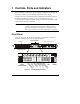
1 Controls, Ports and Indicators Before operating your HP Cache Server Appliance, familiarize yourself with the appliance's controls, ports, and indicators as described in this chapter. The HP Cache Server Appliance hardware configuration and software has been optimized at the factory. The power, LAN, and serial ports are the only connections that are supported. Please contact your HP authorized reseller or HP Support directly for more information.
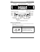
Chapter 1 Controls, Ports and Indicators SCSI Drives SCSI Drives Control Panel Indicators Flexible Disk Drive CD-ROM Drive Power Switch SCSI Drive Status LEDs SCSI Drive Status LEDs Disk 0 Disk 3 Disk 1 Disk 4 Disk 2 Disk 5 Redundant Power Power Power Supply LED Switch DO NOT USE LED Temperature SCSI Activity LED & Fans LED Reset Switch Figure 1-2.
Chapter 1 Controls, Ports and Indicators On/Off LED This green LED provides the power state of the appliance: • Steady Green when the appliance is operating normally LED • Off (unlit) when the appliance is powered off or in standby Reset Switch RESET Push-button Switch DO NOT USE THE RESET SWITCH. Always power the appliance down as described in “Powering-Down the Appliance”.
Chapter 1 Controls, Ports and Indicators SCSI Drive Status LEDs These LEDs indicate the state of the respective SCSI disk drive: • Off for SCSI drive not present. • Steady Green for SCSI drive present. • Alternating Red/Green (fast blink) for a SCSI drive identify. • Steady Red for SCSI drive failure. SCSI Activity LED This LED indicates SCSI Hard Disk activity: • Flickering Green when there is SCSI activity. • Off when there is no power or SCSI activity.
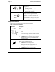
Chapter 1 Controls, Ports and Indicators and valid connection or activity. Table 1-3 describes the LAN LED indicators. Power Lan A Mouse Keyboard USB (2) Lan B PCI Slot (1) External SCSI Connector Video Serial A Figure 1-3. sa2100/sa2150 Rear Panel and Ports AC for PS Bay #1 Power Supply Bay #1 Serial B Mouse USB(2) PCI Slots (3) Parallel Power Supply LED Power Supply Bay #2 Keyboard AC for PS Bay #2 External SCSI Port Video Serial A Lan B Lan A Figure 1-4.
Chapter 1 Controls, Ports and Indicators LED Indicators Table 1-3. Rear Panel LED Indicators Indicator Power Supply LED Definition Each power supply module has a status LED: • Steady Green indicates the power supply module is powered up and operating normally. • Flashing Green indicates that AC current is present and the power supply module is in standby mode (HP Cache Server Appliance is powered off).
Chapter 1 Controls, Ports and Indicators Applying Power to the Appliance Powering-Up the Appliance 1. Ensure that the HP Cache Server Appliance's power cord and network cables are connected prior to powering on the appliance. 2. Press the Power push-button on the front control panel. When you press the power button on the control panel, the appliance powers up and loads the operating system. The system runs a set of power on self-tests (POST) during this process.
Chapter 1 Controls, Ports and Indicators Connecting AC Power to Multiple-Server Configurations The HP Cache Server Appliance temporarily draws a large "inrush current" when first connected to an AC power source. This also occurs when the appliance is in a standby mode (power is turned off, but the power cord is plugged into AC power). The inrush current is much greater than the appliance's normal operating current. The AC power source can handle the inrush current under normal circumstances.
2 Rack Mounting The HP Cache Server Appliance can be rack mounted in a variety of 2 and 4 post racking configurations. The appliances are shipped with the rails needed for 4 post racking configurations already installed. NOTE Read the complete racking instructions in the HP Cache Server Appliance sa2100/sa2150 and sa2200/sa2250 Rack Mounting Supplements on your documentation CD-ROM before attempting to rack mount these appliances.
3 Configuring the Cache Appliance This chapter describes the initial configuration process required to install the cache appliance on the network. Overview The following is an overview of the configuration steps: 1. Configure initial network parameters for LAN A of the appliance a. through DHCP/bootp - OR b. via a VT100 serial console session 2. Accept the settings thereby starting the Traffic Server application. 3. Additional network parameters can be configured through a telnet or VT100 serial session.
Chapter 3 Configuring the Cache Appliance Configuring Initial Network Parameters for LAN A If the appliance has received an IP address through bootp or DHCP and you know the IP address, you may use telnet to access the initial configuration session. (The MAC address is printed on a label on the right side of the appliance as viewed from the front or on the RJ45 connector.) 1. Telnet to the appliance IP address and use hpsaconfig for the user name and hpsa for the password. 2.
Chapter 3 Configuring the Cache Appliance Upon successful completion of the initial configuration, the appliance will start and configure the Traffic Server software to run with the network settings just entered. NOTE After the initial configurations are saved, the network parameters will be saved as a static configuration on the appliance. This is true even if the appliance received the initial IP configuration via bootp or DHCP.
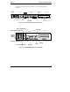
Chapter 3 Configuring the Cache Appliance Monitoring Traffic Server Once Traffic Server is up and running, you can monitor and modify its operation from the Traffic Manager Dashboard. The Dashboard is shown in Figure 3-1. Access Traffic Manager by directing your browser to: http://:8081 where 8081 is the default traffic manager port. The HP Cache Server Appliance Administrator Guide describes how to use Traffic Manager. Figure 3-1.
4 Online Documentation CD-ROM The HP Server Appliance Documentation CD-ROM contains the entire set of documentation for your HP Cache Server Appliance. The CD-ROM provides a web-based interface that allows you to quickly locate information. To use this CD-ROM you must have a browser (either Microsoft Internet Explorer 4.x (or greater), or Netscape Navigator version 4.x (or greater) and Adobe Acrobat Reader version 3.x or greater.
5 Troubleshooting DO NOT remove the cover from the HP Cache Server Appliance. There are no upgradeable or customer-replaceable parts inside the appliance. NOTE This appliance carries a whole unit exchange warranty and no upgrades or replacement of CPU, drives, memory, or any other components are supported. For troubleshooting information go to: http://www.hp.
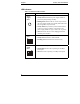
A Specifications This appendix provides the power requirements, operating conditions (environmental requirements), physical requirements and hardware specifications of the HP Cache Server Appliance. Requirements The following tables provide the specifications required for normal operation of the HP Cache Server Appliance. Table A-1. System Power Specifications Parameter Characteristics Input Type Universal input Input Range 100 to 240 VAC at 50/60 Hz Operating Current sa2100/sa2150 2.
Appendix A Specifications Table A-2.
Index C component indicators, 3 configuring Traffic Server, 11 E environmental requirements, 20 F front panel, 1 H HP Cache Server Appliance controls, 2 front panel, 2 indicators, 2 inrush current, 8 power switch, 2 powering down, 2, 3, 7 powering up, 7 rear panel, 4 I indicators LEDs, 3 on/off, 3 inrush current allowing for, 8 specifications, 19 L LAN LEDs, 6 RJ45 port, 6 LAN speed LED, 6 LED indicators front panel, 1 rear panel, 6 link LED, 6 M monitoring Traffic Server, 14 multiple-server configurations