
HP StoreAll Storage Network Best Practices Guide
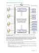
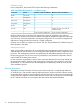
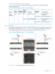
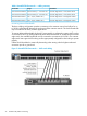
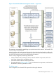
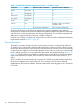
Table Of Contents
- HP StoreAll Storage Network Best Practices Guide
- Contents
- 1 Overview of HP StoreAll Storage networking
- 2 StoreAll 9730 platform networking
- 3 StoreAll 93xx/8x00 platform networking
- 4 Expanding an existing cluster
- 5 Support and other resources
- 6 Documentation feedback
- A BOND modes
- B StoreAll 93xx 10 GbE bonding modes and switch interconnection
- C Install and the default Virtual Connect configuration
Table 7 StoreAll 9730 dedicated management network — IP address usage
Maximum number of addressesMinimum number of addressesSubnetComponent
162user/clusterNodes
1616managementiLO
88managementInterconnect
22managementOA module
11clusterFM VIF
Variable. At least 1 per node (16
included in total)
2userUser VIF
59 for maximum configuration31 for minimum configuration
Because of the manner in which the OA dynamically assigns the addresses to the enclosure
components, all enclosure bays must have addresses assigned for potential management components
even if the bay will not be populated in the shipped configuration. The enclosure management IP
addresses are assigned when the enclosure is initially configured.
Customer use of VLANs or multiple user network VIFs can cause a need for additional IP addresses
beyond those specified in Table 7 (page 40).
Physical description
The physical connection from the enclosure to the customer network is routed through either the
VC modules or the OA modules. Network traffic between the enclosure and the customer network
must traverse these modules to exit the enclosure. All other physical connections are routed internally
via the enclosure’s midplane. Network traffic between servers within an enclosure is routed through
the VC modules and does not count against the total external bandwidth availability. In Figure 13
(page 41), the SAS interconnect modules are combined into a single block to simplify the diagram.
In the actual StoreAll 9730 system, there are still four distinct SAS interconnects in bays 5, 6, 7,
and 8.
The VC modules are cross linked through connectors X7 and X8 to provide redundant paths from
the enclosure midplane to the external network. The connection of X7 and X8 is internally
implemented on the enclosure midplane. External cables should not be plugged into VC connections
X7 and X8.
40 StoreAll 9730 platform networking