
HP StoreAll Storage Network Best Practices Guide
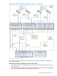
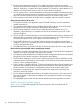
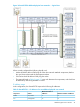
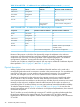
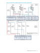
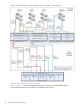
Table Of Contents
- HP StoreAll Storage Network Best Practices Guide
- Contents
- 1 Overview of HP StoreAll Storage networking
- 2 StoreAll 9730 platform networking
- 3 StoreAll 93xx/8x00 platform networking
- 4 Expanding an existing cluster
- 5 Support and other resources
- 6 Documentation feedback
- A BOND modes
- B StoreAll 93xx 10 GbE bonding modes and switch interconnection
- C Install and the default Virtual Connect configuration
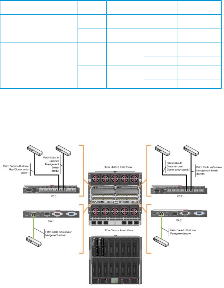
Table 8 StoreAll 9730 dedicated management network — physical mapping
Connection Type
VC External
ConnectionVC Module
Node Physical
Interface
Allocated
Bandwidth
Node
InterfaceNetwork
Primary External
Connection
X6Interconnect Bay 1eth 01 GbBond0Management
Primary External
Connection
X6Interconnect Bay 2eth 3
Primary External
Connection
X5Interconnect Bay 1eth19 GbBond1User, Cluster
LACP trunking with X5X4, X3, X2, X1
Primary External
Connection
X5Interconnect Bay 2eth 2
LACP trunking with X5X4, X3, X2, X1
Physical cabling
The six patch cables shown in Figure 14 (page 43) are the minimum cabling required to attach
an StoreAll 9730 enclosure in the dedicated management network configuration. For maximum
redundancy, each patch cable ideally connects to a physically separate edge switch in the customer
network.
Figure 14 StoreAll 9730 dedicated management network — minimum cabling
Table 9 (page 44) summarizes the necessary connections.
Dedicated management network 43