
HP StoreAll Storage Network Best Practices Guide
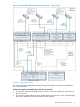

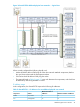
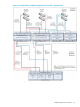
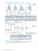
Table Of Contents
- HP StoreAll Storage Network Best Practices Guide
- Contents
- 1 Overview of HP StoreAll Storage networking
- 2 StoreAll 9730 platform networking
- 3 StoreAll 93xx/8x00 platform networking
- 4 Expanding an existing cluster
- 5 Support and other resources
- 6 Documentation feedback
- A BOND modes
- B StoreAll 93xx 10 GbE bonding modes and switch interconnection
- C Install and the default Virtual Connect configuration
collisions:0 txqueuelen:1000
RX bytes:2410457366 (2.2 GiB) TX bytes:105730002 (100.8 MiB)
Memory:f3ea0000-f3ec0000
lo Link encap:Local Loopback
inet addr:127.0.0.1 Mask:255.0.0.0
inet6 addr: ::1/128 Scope:Host
UP LOOPBACK RUNNING MTU:16436 Metric:1
RX packets:3510263 errors:0 dropped:0 overruns:0 frame:0
TX packets:3510263 errors:0 dropped:0 overruns:0 carrier:0
collisions:0 txqueuelen:0
RX bytes:522831923 (498.6 MiB) TX bytes:522831923 (498.6 MiB)
Additional physical user networks
The additional physical user networks configuration builds on the dedicated management network
configuration by adding up to two additional physical networks to the configuration. The additional
physical networks can be set up to carry StoreAll user network traffic. One network carries cluster
and user network traffic. A separate network is dedicated to the management network traffic. A
third and optional fourth network can be used for additional user network traffic.
Motivation
Benefits of additional physical user networks:
• Provides the same benefits and disadvantages as the dedicated management network
configuration.
• Provides physically separated channels for different types of user traffic, which might be
important to the customer for security or manageability.
• Allocates the available 10 Gb bandwidth between the physically separate networks, providing
assured bandwidth for each network.
• Provides a better match with customer networking infrastructure if, for example, the customer
has not yet completely implemented a 10 Gb/s networking infrastructure.
Reasons to choose a different configuration:
• Increased cabling required for a minimum configuration.
• Less flexibility without physical network changes.
• More effort for the customer to ensure that the network is configured correctly.
Logical description
Figure 16 (page 47) illustrates a configuration with two additional user networks. The configuration
is similar to the dedicated management network, but additional bonded interfaces (bond2 and
bond3) are added to support the connections to two additional physical networks. The additional
networks are used for the attachment of file clients. (If there is only one additional user network,
the “bond 3” connections would be eliminated.)
In Figure 16 (page 47), the sample IP addresses were chosen to illustrate the relationship between
components and subnets. The subnet mask and IP address assignments shown here are for illustration
purposes only. Customer address allocation schemes can be done differently.
At the logical layer, all node access to the network is done through a bond interface to allow the
underlying physical layer to implement multiple pathways to the network. The next section describes
how the bond interfaces map to the underlying physical interfaces.
46 StoreAll 9730 platform networking