
HP StoreAll Storage Network Best Practices Guide
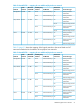
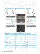
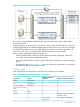
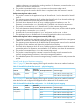
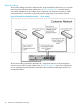
Table Of Contents
- HP StoreAll Storage Network Best Practices Guide
- Contents
- 1 Overview of HP StoreAll Storage networking
- 2 StoreAll 9730 platform networking
- 3 StoreAll 93xx/8x00 platform networking
- 4 Expanding an existing cluster
- 5 Support and other resources
- 6 Documentation feedback
- A BOND modes
- B StoreAll 93xx 10 GbE bonding modes and switch interconnection
- C Install and the default Virtual Connect configuration
The 10 patch cables shown in Figure 20 (page 53) are the minimum cabling required to attach
an StoreAll 9730 enclosure with two additional physical user networks. For maximum redundancy,
each patch cable ideally connects to a physically separate edge switch in the customer network.
Figure 20 StoreAll 9730 two additional physical user networks — physical cabling
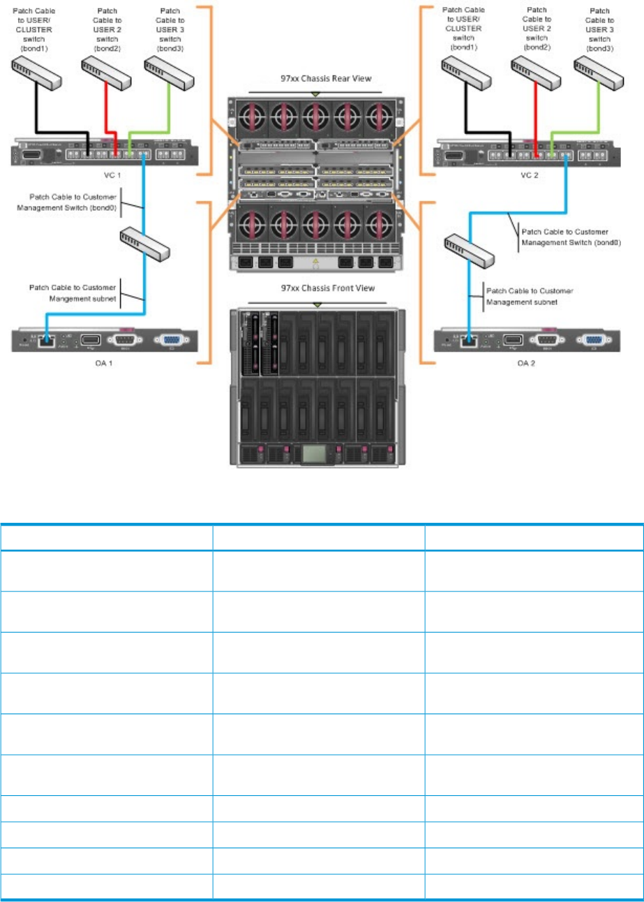
Table 15 StoreAll 9730 two additional physical user networks — cabling summary
DestinationOriginConnection
Customer Edge Switch – Management
network
Interconnect bay 1 – Connector X6Virtual Connect Module 1,
Management Connection
Customer Edge Switch – User/Cluster
network
Interconnect bay 1 – Connector X2Virtual Connect Module 1,
User/Cluster Connection
Customer Edge Switch – Management
network
Interconnect bay 2 – Connector X6Virtual Connect Module 2,
Management Connection
Customer Edge Switch – User/Cluster
network
Interconnect bay 1 – Connector X2Virtual Connect Module 2,
User/Cluster Connection
Customer Edge Switch – Management
network
OA1 – RJ-45 ( Labeled: iLO )Onboard Administrator 1
Customer Edge Switch – Management
network
OA2 – RJ-45 ( Labeled: iLO )Onboard Administrator 2
Customer Edge Switch – User 2 networkInterconnect bay 1 – Connector X4Virtual Connect Module 1, User 2
Customer Edge Switch – User 2 networkInterconnect bay 2– Connector X4Virtual Connect Module 2, User 2
Customer Edge Switch – User 3Interconnect bay 1 – Connector X5Virtual Connect Module 1, User 3
Customer Edge Switch – User 3Interconnect bay 2 – Connector X5Virtual Connect Module 2, User 3
Additional physical user networks 53