
HP StoreAll Storage Network Best Practices Guide
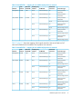
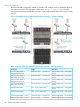
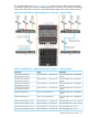
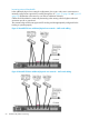
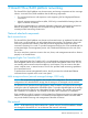
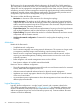
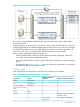
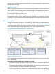
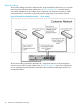
Table Of Contents
- HP StoreAll Storage Network Best Practices Guide
- Contents
- 1 Overview of HP StoreAll Storage networking
- 2 StoreAll 9730 platform networking
- 3 StoreAll 93xx/8x00 platform networking
- 4 Expanding an existing cluster
- 5 Support and other resources
- 6 Documentation feedback
- A BOND modes
- B StoreAll 93xx 10 GbE bonding modes and switch interconnection
- C Install and the default Virtual Connect configuration

interface, otherwise it is routed to the working interface. For illustration, assume that the eth4
interface was chosen for transmission.
4. The packet is transmitted out the eth4 connection to the customer edge switch.
5. Packet routing from this switch to the file client is completed within the customer’s network.
Packet traversing from node to node:
1. The packet is created in the application layer of StoreAll node 1 and is destined for StoreAll
node 2.
2. The operating system determines by IP address that StoreAll node 2 can be reached through
the bond0 interface and queues the packet for that interface.
3. The bond driver determines which of its two underlying physical interfaces to use. For
illustration, assume that the eth5 (StoreAll node 1) interface was chosen for transmission.
4. The packet is transmitted out eth5 (StoreAll node 1) to the customer edge switch.
5. The switch determines that the destination is out one of its other ports, and forwards the packet
to the port that is connected to eth5 (node 2).
6. StoreAll node 2 receives the packet on eth5 and passes it to the bond 0 driver.
7. The application layer on StoreAll node 2 receives the packet from the bond0 interface.
Packet traversing from node to management network (9320 only):
1. The packet is created in the application layer of the node and is destined for the management
interface of channel-A in the network managed storage enclosure.
2. The operating system determines by IP address that the management network can be reached
through the bond0 interface and queues the packet for that interface.
3. The bond driver determines which of its two underlying physical interfaces should be used to
transmit the packet. For illustration, assume that the eth4 interface was chosen for transmission.
4. The packet is transmitted from eth4 to the customer edge switch.
5. The packet is routed through the customer’s network to the edge switch connected to the
network managed storage enclosure's channel-A management interface.
6. The embedded system on the network managed storage controller receives and processes the
packet.
StoreAll node physical hardware mapping
Table 17 (page 59) shows the mapping of the logical networks to the server interface hardware.
Table 17 StoreAll 93xx/8x00 flat network — physical mapping
Connection TypeNode Physical Interface
Allocated
Bandwidth
Node
InterfaceNetwork
Patch cable to customer edge switcheth 410 GbBond0User, cluster,
management
Patch cable to customer edge switcheth 5
Table 18 (page 59) shows the mapping of the logical networks to the server interface hardware
when the servers are configured and shipped with an additional 10 Gb interface card.
Table 18 StoreAll 93xx/8x00 flat configuration – 2x 10 Gb NIC physical mapping
Connection TypeNode Physical Interface
Allocated
Bandwidth
Node
InterfaceNetwork
Patch cable to customer edge switcheth 410 GbBond0User, cluster,
management
Patch cable to customer edge switcheth 5
Patch cable to customer edge switcheth 6
Patch cable to customer edge switcheth 7
Flat network 59