HP StoreAll 8200/9300 Gateway Storage Administrator Guide Abstract This guide describes tasks related to cluster configuration and monitoring, system upgrade and recovery, hardware component replacement, and troubleshooting for the HP 8200/9300 Storage Gateway. It does not document StoreAll file system features or standard Linux administrative tools and commands. For information about configuring and using StoreAll software file system features, see the HP StoreAll OS User Guide.
© Copyright 2014 Hewlett-Packard Development Company, L.P. Confidential computer software. Valid license from HP required for possession, use or copying. Consistent with FAR 12.211 and 12.212, Commercial Computer Software, Computer Software Documentation, and Technical Data for Commercial Items are licensed to the U.S. Government under vendor's standard commercial license. The information contained herein is subject to change without notice.
Contents 1 Product description ....................................................................................8 Storage System Features............................................................................................................8 System components...................................................................................................................8 HP StoreAll software features...................................................................................................
Agile Fusion Manager and failover......................................................................................41 Viewing information about Fusion Managers.........................................................................42 Configuring High Availability on the cluster................................................................................42 What happens during a failover..........................................................................................
Viewing host groups................................................................................................................73 Deleting host groups...............................................................................................................73 Other host group operations....................................................................................................73 Add preferred NIC.................................................................................................
Deleting a routing table entry...................................................................................111 Deleting a network interface.........................................................................................112 Viewing network interface information................................................................................112 10 Licensing.............................................................................................113 Viewing license terms......................
B Warnings and precautions.......................................................................147 Electrostatic discharge information..........................................................................................147 Preventing electrostatic discharge.......................................................................................147 Grounding methods.....................................................................................................147 Equipment symbols..................
1 Product description This guide provides information about configuring, monitoring, maintaining HP StoreAll 8200/ 9300 Storage Gateways. IMPORTANT: It is important to keep regular backups of the cluster configuration. Storage System Features The HP StoreAll Storage Systems are highly available, scale-out storage solutions for file data workloads. The systems combine HP StoreAll File Serving Software with HP server and storage hardware to create an expansible cluster of file serving nodes.
High availability and redundancy The segmented architecture is the basis for fault resilience-loss of access to one or more segments does not render the entire file system inaccessible. Individual segments can be taken offline temporarily for maintenance operations and then returned to the file system. To ensure continuous data access, StoreAll software provides manual and automated failover protection at various points: • Server.
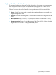
2 Getting started IMPORTANT: Follow these guidelines when using your system: • Do not modify any parameters of the operating system or kernel, or update any part of the storage unless instructed to do so by HP; otherwise, the system could fail to operate properly. • File serving nodes are tuned for file serving operations. With the exception of supported backup programs, do not run other applications directly on the nodes.
• Remote replication. Use this feature to replicate changes in a source file system on one cluster to a target file system on either the same cluster or a second cluster. • Data retention and validation. Use this feature to manage WORM and retained files. • Antivirus support. This feature is used with supported Antivirus software, allowing you to scan files on a StoreAll file system. • StoreAll software snapshots.
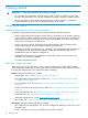
The following operations can be performed only from the StoreAll Management Console: • Scheduling recurring data validation scans • Scheduling recurring software snapshots • Scheduling recurring block snapshots Using the StoreAll Management Console The StoreAll Management Console is a browser-based interface to the Fusion Manager. See the release notes for the supported browsers and other software required to view charts on the dashboard. You can open multiple Management Console windows as necessary.
System Status The System Status section lists the number of cluster events that have occurred in the last 24 hours. There are three types of events: Alerts. Disruptive events that can result in loss of access to file system data. Examples are a segment that is unavailable or a server that cannot be accessed. Warnings. Potentially disruptive conditions where file system access is not lost, but if the situation is not addressed, it can escalate to an alert condition.
Statistics Historical performance graphs for the following items: • Network I/O (MB/s) • Disk I/O (MB/s) • CPU usage (%) • Memory usage (%) On each graph, the X-axis represents time and the Y-axis represents performance. Use the Statistics menu to select the servers to monitor (up to two), to change the maximum value for the Y-axis, and to show or hide resource usage distribution for CPU and memory. Recent Events The most recent cluster events.
Customizing the display You can customize the tables in the GUI to change the sort order of table columns, or to specify which columns in the table to display. • Mouse over any column label. If the label field changes color and a pointer displays on the field's right edge, the field can be customized. Click the pointer to open a menu listing the available options. • Select Ascending or Descending as the ASCII sort order for that column.
Using the CLI The administrative commands described in this guide must be executed on the Fusion Manager host and require root privileges. The commands are located in $IBRIXHOME/bin. For complete information about the commands, see the HP StoreAll OS CLI Reference Guide. When using ssh to access the machine hosting the Fusion Manager, specify the IP address of the Fusion Manager user VIF.
Changing passwords You can change the following passwords on your system: • Hardware passwords. See the documentation for the specific hardware for more information. • Root password. Use the passwd(8) command on each server. • StoreAll software user password. This password is created during installation and is used to log in to the GUI. The default is ibrix. You can change the password using the Linux passwd command. # passwd ibrix You will be prompted to enter the new password.
Port Description 662/tcp, 662/udp mount daemon 2020/tcp, 2020/udp stat 4000:4003/tcp stat outgoing reserved for use by a custom application (CMU) and can be disabled if not used 137/udp Between file serving nodes and SMB clients (user network) 138/udp 139/tcp 445/tcp 9000:9002/tcp Between file serving nodes and StoreAll clients (user network) 9000:9200/udp 9170 TCP/UDP to 9202 TCP/UDP Continuous remote replication 20/tcp, 20/udp Between file serving nodes and FTP clients (user network) 21/tc
Overview HP StoreAll OS 6.5 (or later) supports the following versions: • HP IRS 7.0.8 (plus Content Level Update 7.0.8.1)—Version 7.0.8 works independently to provide remote support for all devices. HP SIM is not required to provide remote support. NOTE: HP IRS 7.0.9 is also supported (release date pending at time of publication) • HP SIM 7.3—Although not required, you can install and use HP SIM 7.3 to manage cluster devices.
Table 1 Hardware support Product name Server Storage Chassis StoreAll 9730 Yes Yes Yes 1 IBRIX X9720 Yes No Yes StoreAll 9320 Yes Yes Not applicable StoreAll 9300 Yes Not supported2 Not applicable StoreAll 8800 Yes Yes Not applicable StoreAll 8200 Yes Not supported2 Not applicable 1 The MDS600 storage device is not supported by HP IRS. No storage alerts are generated. 2 You may configure the attached storage separately for HP Support.
1. Select Cluster Configuration in the upper Navigator and then select Phone Home in the lower Navigator. The Phone Home Setup panel shows the current configuration. 2. Click Enable to configure the settings on the Phone Home Settings dialog box. When entering information in this dialog box, consider the following: • You must enter the IP address of the CMS on which HP IRS is installed. All other fields are optional.
3. Click OK when finished. To configure Phone Home using the CLI, see the ibrix_phonehome command in the HP StoreAll OS CLI Reference Guide. Compiling the MIB IMPORTANT: You must compile and manually register the StoreAll MIB file if you use HP Systems Insight Manager to view events. 1. 2. 3. Download ibrixMib.txt from /usr/local/ibrix/doc/. Rename the file to ibrixMib.mib. In HP Systems Insight Manager, complete the following steps: a.
Configuring entitlements Entitlements must be entered for the applicable devices in your configuration (servers, storage, chassis). This information includes the hardware-related information (product name, serial number, and product number) and the IP address or host name of the device. When entering entitlements, remember that: • The device must be present in the cluster. • You must enter entitlements for each device individually. • The Chassis selection only applies to the 9730 and X9720.
To use the CLI to configure entitlements, see the ibrix_phonehome command in the HP StoreAll OS CLI Reference Guide for more information. Configuring server entitlements Entitlements must be entered for the applicable devices in your configuration (servers, storage, chassis). This information includes the hardware-related information (product name, serial number, and product number) and the IP address or host name of the device.
Configuring chassis entitlements Entitlements must be entered for the applicable devices in your configuration (servers, storage, chassis). This information includes the hardware-related information (product name, serial number, and product number) and the IP address or host name of the device. When entering entitlements, remember that: • The device must be present in the cluster. • You must enter entitlements for each device individually. • The Chassis selection only applies to the 9730 and X9720.
2. 3. 4. 5. Under Home, select Discovery. Select the Sources tab and then select New. You can discover devices by entering a single IP address or a range of IP addresses, or listing several IP addresses. Enter the IP address (or addresses) into the table of IP addresses. Select Start Discovery to begin device discovery. While the device discovery is in process, you will see Discovery Status: Running. Once device discovery is completed, you will see Discovery Status: Stopped.
Discovering devices using HP SIM IMPORTANT: If you are running StoreAll OS 6.5 or later and IRS 7.0.8, device discovery through HP SIM is only required if you want to manage devices through HP SIM. Otherwise, you can skip this procedure. HP Systems Insight Manager (SIM) uses the SNMP protocol to discover and identify StoreAll systems automatically. Discovering the Fusion Manager IP address leads to discovery of the individual devices in the cluster (nodes, storage (MSA), and Onboard Administrator).
6. Enter the read community string and click Add. This string should match the entry in the Read Community String field from the Phone Home Settings window in the StoreAll Management Console. If the strings are not identical, the Fusion Manager IP might be discovered as “Unknown.” CAUTION: If you add, change, or delete the virtual interface (VIF) IP address after the Phone Home configuration is updated, you must rediscover the Fusion Manager using the new VIF IP in HP SIM.
1 When running a StoreAll OS version earlier than 6.5, all devices discovered through HP SIM 7.3 will have a System Subtype of StoreAll. The following figures show examples of discovered devices in HP SIM 7.3 when running StoreAll OS 6.5 or later.
Figure 6 Discovery of StoreAll 9730 cluster (earlier StoreAll OS) Figure 7 Discovery of StoreAll 9320 cluster (earlier StoreAll OS) Figure 8 Discovery of StoreAll 9300 cluster (earlier StoreAll OS) The following figure shows an example of discovered devices on HP SIM 7.1 when running StoreAll OS 6.3 or earlier. Figure 9 Discovered devices in HP SIM 7.
Consider the following for the various upgrade scenarios and how each affects the branding that is displayed in HP SIM: • If you upgrade to StoreAll OS 6.5 and Phone Home was not previously configured, when you do configure Phone Home, it will be with the new StoreAll branding names (see Table 3 (page 28)). • If Phone Home was configured prior to upgrading to StoreAll OS 6.5, there are four scenarios to consider: ◦ If Phone Home is not reconfigured after the upgrade, HP SIM 7.
Rescanning the Phone Home configuration Use the Rescan function to update the Phone Home configuration when devices are added to or removed from the cluster. The operation enables Phone Home on newly added devices (such as servers, storage, and chassis) and removes details for devices that are no longer in the cluster. To use the Rescan function: 1. Click Cluster Configuration in the upper Navigator. 2. Click Phone Home in the lower Navigator. The Phone Home Setup panel appears. 3. Click Rescan.
A cluster node was not configured in Phone Home If a cluster node was down during the Phone Home configuration, the log file includes the following message: SEVERE: Sent event server.status.down: Server down After the node is up, rescan Phone Home to add the node to the configuration. Configuring Phone Home could generate a large number of error messages Configuring Phone Home enables the hp-snmp-agents service internally.
hpsp_credmgmt --update-cred -s couplet:couplet/array//mgmtport_a/ro --cred-type upwpair --cred-username monitor --cred-password '!monitor' hpsp_credmgmt --update-cred -s couplet:couplet/array//mgmtport_b/rw --cred-type upwpair --cred-username manage --cred-password '!manage' hpsp_credmgmt --update-cred -s couplet:couplet/array//mgmtport_b/ro --cred-type upwpair --cred-username monitor --cred-password '!monitor' 3.
The Customer Entered Serial Number and Customer Entered Product Number is displayed when you run the ibrix_phonehome -l command. Details for the Standby OA device must be entered manually In HP SIM, you must manually update the CMS IP address and Custom Delivery ID details for the Standby OA device.
3 Configuring virtual interfaces for client access StoreAll software uses a cluster network interface to carry Fusion Manager traffic and traffic between file serving nodes. This network is configured as bond0 when the cluster is installed. To provide failover support for the Fusion Manager, a virtual interface is created for the cluster network interface.
3. To assign the IFNAME a default route for the parent cluster bond and the user VIFS assigned to FSNs for use with SMB/NFS, enter the following ibrix_nic command at the command prompt: # ibrix_nic -r -n IFNAME -h HOSTNAME-A -R 4. Configure backup monitoring, as described in “Configuring backup servers” (page 37). Creating a bonded VIF NOTE: The examples in this chapter use the unified network and create a bonded VIF on bond0.
For example: # # # # ibric_nic ibric_nic ibric_nic ibric_nic -m -m -m -m -h -h -h -h node1 node2 node3 node4 -A -A -A -A node2/bond0:1 node1/bond0:1 node4/bond0:1 node3/bond0:1 Configuring automated failover To enable automated failover for your file serving nodes, execute the following command: ibrix_server -m [-h SERVERNAME] Example configuration This example uses two nodes, ib50-81 and ib50-82. These nodes are backups for each other, forming a backup pair.
NOTE: Because the backup NIC cannot be used as a preferred network interface for StoreAll clients, add one or more user network interfaces to ensure that HA and client communication work together. Configuring VLAN tagging VLAN capabilities provide hardware support for running multiple logical networks over the same physical networking hardware. To allow multiple packets for different VLANs to traverse the same physical interface, each packet must have a field added that contains the VLAN tag.
To determine whether link state monitoring is enabled on an iSCSI interface, run the following command: ibrix_nic -l Next, check the LINKMON column in the output. The value yes means that link state monitoring is enabled; no means that it is not enabled.
4 Configuring failover This chapter describes how to configure failover for agile management consoles, file serving nodes, network interfaces, and HBAs. Agile management consoles The agile Fusion Manager maintains the cluster configuration and provides graphical and command-line user interfaces for managing and monitoring the cluster. The agile Fusion Manager is installed on all file serving nodes when the cluster is installed. The Fusion Manager is active on one node, and is passive on the other nodes.
The failover will take approximately one minute. To see which node is now the active Fusion Manager, enter the following command: ibrix_fm -i The failed-over Fusion Manager remains in nofmfailover mode until it is moved to passive mode using the following command: ibrix_fm -m passive NOTE: A Fusion Manager cannot be moved from nofmfailover mode to active mode.
What happens during a failover The following actions occur when a server is failed over to its backup: 1. The Fusion Manager verifies that the backup server is powered on and accessible. 2. The Fusion Manager migrates ownership of the server’s segments to the backup and notifies all servers and StoreAll clients about the migration. This is a persistent change. If the server is hosting the active FM, it transitions to another server. 3.
5. 6. Click Next to continue. The NIC HA Setup window appears. Use the NIC HA Setup window to configure NICs that will be used for data services such as SMB or NFS. You can also designate NIC HA pairs on the server and its backup and enable monitoring of these NICs. If you need to add NICs, click Add NIC. the Add NIC dialog box appears. See "Adding a NIC" for more information.
7. Next, enable NIC monitoring on the VIF. Select the new user NIC and click NIC HA. The NIC HA Config dialog box appears. See “Configuring HA on a NIC” (page 47) for more information. After completing the NIC HA Config dialog box, the NIC HA Setup window appears again. Continue configuring High Availability for any other NICs. When that is completed, click Finish to exist the wizard.
Managing power sources To view the power source for a server, select the server on the Servers panel, and then select Power from the lower Navigator. The Power Source panel shows the power source configured on the server when HA was configured. You can add or remove power sources on the server, and can power the server on or off, or reset the server. Adding a NIC On the Add NIC dialog box: 1. Complete the following fields as needed: NOTE: 2. 46 Name and IP Address are required fields.
Configuring HA on a NIC On the NIC HA Config dialog box: 1. Select Enable NIC Monitoring. 2. Select the NIC to be the standby NIC to the backup server (the server listed in the Standby Server box). The standby NIC you select must valid and available. If you need to create a standby NIC, select New Standby NIC in this box, which opens the Add NIC dialog box. Enter the applicable details and then return to the NIC HA Config dialog box. 3. Click OK when finished. The NIC HA configuration is now complete.
Server NICs This panel displays information about the NICs on the selected server and allows you to add, modify, migrate, or remove an interface. The options are: Add: Add a new interface to the selected server. When you click Add, the Add NIC dialog box opens, and you can specify the name of the new interface. To specify a VIF, add the VIF suffix (:) to the physical interface name (for example, bond0:2). Modify: Change the properties for the selected NIC.
Field Description Backup The name of the standby server, if assigned. HA Whether high availability features are on or off. A File Serving Node can be in the following states: • Registered: Configured but not operational. • Up: Operational. • Up-Alert: Server has encountered a condition that has been logged. Check the events log on the Events tab.
backups. Using programmable power sources prevents a "split-brain scenario" between a failing file serving node and its backup, allowing the failing server to be centrally powered down by the Fusion Manager in the case of automated failover, and manually in the case of a forced manual failover. StoreAll software works with iLO, IPMI, OpenIPMI, and OpenIPMI2 integrated power sources.
Disassociate a server from a power source: You can dissociate a file serving node from a power source by dissociating it from slot 1 (its default association) on the power source. Use the following command: ibrix_hostpower -d -s POWERSOURCE -h HOSTNAME Delete a power source: To conserve storage, delete power sources that are no longer in use. If you are deleting multiple power sources, use commas to separate them.
To fail back a node from the GUI, select the node on the Servers panel and then click Failback on the Summary panel. On the GUI, select the node on the Servers panel and then click Failback on the Summary pane On the CLI, run the following command, where HOSTNAME is the failed-over node: ibrix_server -f -U -h HOSTNAME After failing back the node, check the Summary panel or run the ibrix_server -l command to determine whether the failback completed fully. If the failback is not complete, contact HP Support.
Adding standby-paired HBA ports Identifying standby-paired HBA ports to the configuration database allows the Fusion Manager to apply the following logic when they fail: • If one port in a pair fails, do nothing. Traffic will automatically switch to the surviving port, as configured by the HBA vendor or the software. • If both ports in a pair fail, fail over the server’s segments to the standby server.
Field Description Port State Operational state of the port. Backup Port WWN WWPN of the standby port for this port (standby-paired HBAs only). Monitoring Whether HBA monitoring is enabled for this port. Servers modify HBA properties Servers modify HBA properties page This dialog allows you to enable or disable the monitoring feature for HBA High Availability.
For example, to view a summary report for file serving nodes xs01.hp.com and xs02.hp.com: ibrix_haconfig -l -h xs01.hp.com,xs02.hp.com Host HA Configuration Power Sources Backup Servers Auto Failover Nics Monitored Standby Nics HBAs Monitored xs01.hp.com FAILED PASSED PASSED PASSED FAILED PASSED FAILED xs02.hp.
4. After the core dump is created, the failed node reboots and its state changes to Up, FailedOver. Prerequisites for setting up the crash capture The following parameters must be configured in the ROM-based setup utility (RBSU) before a crash can be captured automatically on a file server node in failed condition. 1. Start RBSU. Reboot the server, and then Press F9 Key. 2. Highlight the System Options option in main menu, and then press the Enter key.
2. Tune Fusion Manager to set the DUMPING status timeout by entering the following command: ibrix_fm_tune -S -o dumpingStatusTimeout=240 This command is required to delay the failover until the crash kernel is loaded; otherwise, Fusion Manager will bring down the failed node.
5 Configuring cluster event notification Cluster events There are three types of cluster events: Table 5 Event types Icon Type Description Alerts Disruptive events that can result in loss of access to file system data (for example, a segment is unavailable or a server is unreachable).
When viewing events on the Events window, the following information is displayed: • Level: Indicates the event type by icon (see Table 5 (page 58)). This column is sortable. • Time: Indicates the time the event originated on the management server. • Event: Displays the details of the event, including suggested actions. You can be notified of cluster events by email or SNMP traps. : The StoreAll event system does not report events from the MSA array.
Managing events and email notification Use the Manage Email Notifications feature to create or modify event associations with new or existing email addresses. You can also remove associations. Select Cluster Configuration in the upper Navigator and Email > Events in the lower Navigator. On the Events Notified by Email window, select Manage Email Notifications. To update event notifications for existing email recipients: 1. Select the applicable email address in the Current destination email addresses box.
decryption. Both authentication and privacy, and their passwords, are optional and will use default settings where security is less of a concern. • With users validated, the VACM determines which managed objects these users are allowed to access.
Click OK when finished. Configuring trapsink settings A trapsink is the host destination where agents send traps, which are asynchronous notifications sent by the agent to the management station. A trapsink is specified either by name or IP address. StoreAll software supports multiple trapsinks; you can define any number of trapsinks of any SNMP version, but you can define only one trapsink per host, regardless of the version.
The Fusion Manager automatically creates the excludeAll view that blocks access to all OIDs. This view cannot be deleted; it is the default read and write view if one is not specified for a group with the ibrix_snmpgroup command. The catch-all OID and mask are: OID = .1 Mask = .1 Consider these examples, where instance .1.3.6.1.2.1.1 matches, instance .1.3.6.1.4.1 matches, and instance .1.2.6.1.2.1 does not match. OID = .1.3.6.1.4.1.18997 Mask = .1.1.1.1.1.1.1 OID = .1.3.6.1.2.1 Mask = .1.1.0.1.0.
Viewing SNMP notifications View the current configuration for sending out event notifications via SNMP traps. This includes information about trapsinks (servers that receive SNMP traps), as well as the association of events with these trapsinks. A single event can generate notifications to multiple trapsinks. Also, different sets of events can generate notifications to different trapsinks. The following information is available about the SNMP Agent: System Description Name of the SNMP Agent.
In the Email Configuration section, set the options: • Notification Level. Select the minimum severity for which the system should send notifications: Critical (only); Error (and Critical); Warning (and Error and Critical); Informational (all). The default is none, which disables email notification. • SMTP Server address. The IP address of the SMTP mail server to use for the email messages.
6 Configuring system backups Backing up the Fusion Manager configuration The Fusion Manager configuration is automatically backed up whenever the cluster configuration changes. The backup occurs on the node hosting the active Fusion Manager. The backup file is stored at /tmp/fmbackup.zip on that node. The active Fusion Manager notifies the passive Fusion Manager when a new backup file is available. The passive Fusion Manager then copies the file to /tmp/fmbackup.
hard quota limit for the directory tree has been exceeded, NDMP cannot create a temporary file and the restore operation fails. • NDMP does not support the case-insensitivity property in a file system or a directory within a file system and will not back up a file system with this property enabled. As a result, after restoring a file system, the case-insensitivity property is not restored to directories on the file system. This is the expected behavior.
Click Synchronize on the NDMP Configuration Summary window to copy the configuration to all nodes. To configure NDMP using the CLI, see the ibrix_ndmpconfig command in the HP StoreAll OS CLI Reference Guide. Managing NDMP processes Normally all NDMP actions are controlled from the DMA.
To see similar information for completed sessions, select NDMP Backup > Session History. To view or cancel sessions from the CLI, see the ibrix_ndmpsession command in the HP StoreAll OS CLI Reference Guide. Starting, stopping, or restarting an NDMP Server When a node is booted, the NDMP Server is started automatically.
NDMP events An NDMP Server can generate three types of events: INFO, WARN, and ALERT. These events are displayed on the GUI and can be viewed with the ibrix_event command. INFO events. Identifies when major NDMP operations start and finish, and also report progress. For example: 7012:Level 3 backup of /mnt/ibfs7 finished at Sat Nov 7 21:20:58 PST 2011 7013:Total Bytes = 38274665923, Average throughput = 236600391 bytes/sec. WARN events.
7 Creating host groups for StoreAll clients Overview A host group is a named set of StoreAll clients. Host groups provide a convenient way to centrally manage clients. You can put different sets of clients into host groups and then perform the following operations on all members of the group: • Create and delete mount points • Mount file systems • Prefer a network interface • Tune host parameters • Set allocation policies Host groups are optional.
For example, suppose that you want all clients to be able to mount file system ifs1 and to implement a set of host tunings denoted as Tuning 1, but you want to override these global settings for certain host groups. To do this, mount ifs1 on the clients host group, ifs2 on host group A, ifs3 on host group C, and ifs4 on host group D, in any order. Then, set Tuning 1 on the clients host group and Tuning 2 on host group B.
Viewing host groups To view clients that are members of a host group, select the host group in the Hostgroups window. The member information displays in the Members panel in the lower half of the window. The member information includes the name, IP address and Universal Unique Identifer (UUID) of the client. Deleting host groups When you delete a host group, its members are reassigned to the parent of the deleted group. Select the applicable host group on the Hostgroups window and click Delete.
The dialog contains the following fields: Field Description Mountpoint The path that will be used as the mountpoint on each client. Filesystem The files system to be mounted. atime Update the inode access time when the inode is accessed. nodiratime Do not update the directory inode access time when the directory is accessed. nodquotstatfs Do not show files system usage reporting based on directory tree quota limits.
8 Monitoring cluster operations This chapter describes how to monitor the operational state of the cluster and how to monitor cluster health. Monitoring hardware The GUI displays status, firmware versions, and device information for the servers, virtual chassis, and system storage included in 8200/9300 systems. Monitoring servers To view information about the server and chassis included in your system. 1. Select Servers from the Navigator tree. The Servers panel lists the servers included in each chassis.
Select the server component that you want to view from the lower Navigator panel, such as NICs.
The following are the top-level options provided for the server: NOTE: Information about the Hardware node can be found in “Monitoring hardware components” (page 79). • HBAs.
• • • • ◦ Monitoring ◦ State NICs. The NICs panel shows all NICs on the server, including offline NICs. The NICs panel displays the following information: ◦ Name ◦ IP ◦ Type ◦ State ◦ Route ◦ Standby Server ◦ Standby Interface Mountpoints. The Mountpoints panel displays the following information: ◦ Mountpoint ◦ Filesystem ◦ Access NFS. The NFS panel displays the following information: ◦ Host ◦ Path ◦ Options CIFS.
• • Events. The Events panel displays the following information: ◦ Level ◦ Time ◦ Event Hardware. The Hardware panel displays the following information: ◦ The name of the hardware component. ◦ The information gathered in regards to that hardware component. See “Monitoring hardware components” (page 79) for detailed information about the Hardware panel. Monitoring hardware components The Management Console provides information about the server hardware and its components.
• Message1 • Diagnostic Message1 1 Column dynamically appears depending on the situation. Obtain detailed information for hardware components in the server by clicking the nodes under the Server node.
Table 7 Obtaining detailed information about a server Panel name Information provided CPU • Status • Type • Name • UUID • Model • Location ILO Module • Status • Type • Name • UUID • Serial Number • Model • Firmware Version • Properties Memory DiMM • Status • Type • Name • UUID • Location • Properties NIC • Status • Type • Name • UUID • Properties Power Management Controller • Status • Type • Name • UUID • Firmware Version Storage Cluster • Status • Type • Name • UUID Monitoring hardware 81
Table 7 Obtaining detailed information about a server (continued) Panel name Information provided Drive: Displays information about each drive in a storage cluster. • Status • Type • Name • UUID • Serial Number • Model • Firmware Version • Location • Properties Storage Controller (Displayed for a server) • Status • Type • Name • UUID • Serial Number • Model • Firmware Version • Location • Message • Diagnostic message Volume Displays volume information for each server.
Table 7 Obtaining detailed information about a server (continued) Panel name Information provided Temperature Sensor: Displays information for each temperature sensor. • Status • Type • Name • UUID • Locations • Properties Monitoring storage and storage components Select Vendor Storage from the Navigator tree to display status and device information for storage and storage components. The Summary panel shows details for a selected vendor storage.
The Management Console provides a wide-range of information in regards to vendor storage. Drill down into the following components in the lower Navigator tree to obtain additional details: • Servers. The Servers panel lists the host names for the attached storage. • LUNs. The LUNs panel provides information about the LUNs in a storage cluster. See “Managing LUNs in a storage cluster” (page 84) for more information.
• Storage Switch. (Applies only to the HP StoreAll 9730/X9720) The Storage Switch panel provides detailed information about the storage switches. • LUNs. The LUNs panel provides information about the LUNs in a storage cluster. For HP StoreAll 9730/X9720 systems, the Vendor Storage panel lists the HP 600 Modular Disk Systems (MDS600) included in the system. The Summary panel shows details for the selected MDS600. Select a component from the lower Navigator to see details for the selected storage.
File serving nodes can be in one of three operational states: Normal, Alert, or Error. These states are further broken down into categories describing the failover status of the node and the status of monitored NICs and HBAs. State Description Normal Up: Operational. Alert Up-Alert: Server has encountered a condition that has been logged. An event will appear in the Status tab of the GUI, and an email notification may be sent.
Viewing events The GUI dashboard specifies the number of events that have occurred in the last 24 hours. Click Events in the GUI Navigator to view a report of the events. You can also view events that have been reported for specific file systems or servers. On the CLI, use the ibrix_event command to view information about cluster events.
Monitoring cluster health To monitor the functional health of file serving nodes and StoreAll clients, execute the ibrix_health command. This command checks host performance in several functional areas and provides either a summary or a detailed report of the results. Health checks The ibrix_health command runs these health checks on file serving nodes: • Pings remote file serving nodes that share a network with the test hosts.
The following is an example of the output from the ibrix_health -i command: [root@r211-s16 ~]# ibrix_health -i -h r211-s15 Overall Health Checker Results - PASSED ======================================= Host Summary Results ==================== Host Result Type State Network Last Update -------- ------ ------ ----- ---------- ----------r211-s15 PASSED Server Up 10.2.11.
Result Information ----------------------------------------------------- ----------------------User nic r211-s15/bond0:3 pingable from host r211-s16 PASSED Check : Physical volumes are readable ===================================== Check Description Result Result Information -------------------------------------------------------------------- -----------------Physical volume PtJtdz-TXe3-v6Kf-XvQB-uGHz-9nJe-BTFteM readable PASSED /dev/mpath/mpath2 Physical volume gzxyTW-oiRT-THMc-zE2i-q7x0-3Kbj-YuyWLn readab
The -f option displays results only for hosts that failed the check. The -s option includes information about the file system and its segments. The -v option includes details about checks that received a Passed or Warning result.
Result Information --------------------------------------------------------------------------------------------------------------r38-s1 engine uuid matches on Iad and Fusion Manager r38-s1 IP address matches on Iad and Fusion Manager r38-s1 network protocol matches on Iad and Fusion Manager r38-s1 engine connection state on Iad is up r38-s2 engine uuid matches on Iad and Fusion Manager r38-s2 IP address matches on Iad and Fusion Manager r38-s2 network protocol matches on Iad and Fusion Manager r38-s2 engine
-f NFS statistics -h The file serving nodes to be included in the report Sample output follows: ---------Summary-----------HOST Status CPU Disk(MB/s) Net(MB/s) lab12-10.hp.com Up 0 22528 616 ---------IO-----------HOST Read(MB/s) Read(IO/s) Read(ms/op) Write(MB/s) Write(IO/s) Write(ms/op) lab12-10.hp.com 22528 2 5 0 0.00 ---------Net-----------HOST In(MB/s) In(IO/s) Out(MB/s) Out(IO/s) lab12-10.hp.com 261 3 355 2 ---------Mem-----------HOST MemTotal(MB) MemFree(MB) SwapTotal(MB) SwapFree(MB) lab12-10.hp.
9 Maintaining the system Shutting down the system To shut down the system completely, first shut down the StoreAll software, and then power off the system hardware. Shutting down the StoreAll software Use the following procedure to shut down the StoreAll software. Unless noted otherwise, run the commands from the node hosting the active Fusion Manager. 1. Stop any active remote replication, data tiering, or rebalancer tasks.
7. Unmount all file systems on the cluster nodes: ibrix_umount -f To unmount file systems from the GUI, select Filesystems > unmount. 8. Verify that all file systems are unmounted: ibrix_fs -l If a file system fails to unmount on a particular node, continue with this procedure. The file system will be forcibly unmounted during the node shutdown. 9. Shut down all StoreAll Server services and verify the operation: # pdsh -a /etc/init.d/ibrix_server stop | dshbak # pdsh -a /etc/init.
1. 2. 3. Power on the node hosting the active Fusion Manager. Power on the file serving nodes (*root segment = segment 1; power on owner first, if possible). Monitor the nodes on the GUI and wait for them all to report UP in the output from the following command: ibrix_server -l 4. Mount file systems and verify their content.
HOSTNAME is the name of the node that you just rebooted. Starting and stopping processes You can start, stop, and restart processes and can display status for the processes that perform internal StoreAll software functions. The following commands also control the operation of PostgreSQL on the machine. The PostgreSQL service is available at /usr/local/ibrix/init/. To start and stop processes and view process status on the Fusion Manager, use the following command: /etc/init.
a. Back up the current configuration: mv /etc/ibrix/iadconf.xml /etc/ibrix/iadconf.xml.oldcp -p /etc/ibrix/fusion.xml /etc/ibrix/fusion.xml.old b. Create the new configuration file with the new cluster name: /usr/local/ibrix/bin/register_server -p -c -n -H /usr/local/ibrix -a none -x 9.
The General Tunings dialog box specifies the communications protocol (TCP or UDP) and the number of admin and server threads. The IAD Tunings dialog box configures the StoreAll administrative daemon. The Module Tunings dialog box adjusts various advanced parameters that affect server operations.
On the Servers dialog box, select the servers to which the tunings should be applied. To tune nodes using the CLI, see the ibrix_host_tune command in the HP StoreAll OS CLI Reference Guide.
Tuning StoreAll clients locally Linux clients. Use the ibrix_lwhost command to tune host parameters. For example, to set the communications protocol: ibrix_lwhost --protocol -p {tcp|udp} To list host tuning parameters that have been changed from their defaults: ibrix_lwhost --list See the ibrix_lwhost command description in the HP StoreAll OS CLI Reference Guide for other available options. Windows clients. Click the Tune Host tab on the Windows StoreAll client GUI.
The Change Ownership dialog box reports the status of the servers in the cluster and lists the segments owned by each server. In the Segment Properties section of the dialog box, select the segment whose ownership you are transferring, and click Change Owner.
The new owner of the segment must be able to see the same storage as the original owner. The Change Segment Owner dialog box lists the servers that can see the segment you selected. Select one of these servers to be the new owner. The Summary dialog box shows the segment migration you specified. Click Back to make any changes, or click Finish to complete the operation. To migrate ownership of segments from the CLI, see the ibrix_fs command in the HP StoreAll OS CLI Reference Guide.
On the Evacuate Advanced dialog box, locate the segment to be evacuated and click Source. Then locate the segments that will receive the data from the segment and click Destination. If the file system is tiered, be sure to select destination segments on the same tier as the source segment. The Summary dialog box lists the source and destination segments for the evacuation. Click Back to make any changes, or click Finish to start the evacuation.
The Active Tasks panel reports the status of the evacuation task. When the task is complete, it will be added to the Inactive Tasks panel. 4. When the evacuation is complete, run the following command to retire the segment from the file system: ibrix_fs -B -f FSNAME -n BADSEGNUMLIST The segment number associated with the storage is not reused. The underlying LUN or volume can be reused in another file system or physically removed from the storage solution when this step is complete. 5.
3015A4021.C34A994C, poid 3015A4021.C34A994C, primary 4083040FF.7793558E poid 4083040FF.7793558E Use the inum2name utility to translate the primary inode ID into the file name. Removing a node from a cluster In the following procedure, the cluster contains four nodes: FSN1, FSN2, FSN3, and FSN4. FSN4 is the node being removed. The user NIC for FSN4 is bond0:1. The file system name is ibfs1, which is mounted on /ibfs1 and shared as ibfs1 through NFS and SMB .
7. Remove all NFS and SMB shares from FSN4 (in this example, ibfs1 is shared via NFS and CIFS): ibrix_exportfs -U -h FSN4 -p *:/ibfs1 ibrix_cifs -d -s ibfs1 -h FSN4 8. Unmount ibfs1 from FSN4 and delete the mountpoint on FSN4 from the cluster: ibrix_umount -f ibfs1 -h FSN4 ibrix_mountpoint -d -h FSN4 -m /ibfs1 9. Remove FSN4 from AgileFM quorum participation: ibrix_fm -u FSN4 10. Delete FSN4 from the cluster: ibrix_server -d -h FSN4 11. Reconfigure High Availability on FSN3, if needed. 12.
When creating user network interfaces for file serving nodes, keep in mind that nodes needing to communicate for file system coverage or for failover must be on the same network interface. Also, nodes set up as a failover pair must be connected to the same network interface. For a highly available cluster, HP recommends that you put protocol traffic on a user network and then set up automated failover for it (see “Configuring High Availability on the cluster” (page 42)).
Setting network interface options in the configuration database To make a VIF usable, execute the following command to specify the IP address and netmask for the VIF. You can also use this command to modify certain ifconfig options for a network. ibrix_nic -c -n IFNAME -h HOSTNAME [-I IPADDR] [-M NETMASK] [-B BCASTADDR] [-T MTU] For example, to set netmask 255.255.0.0 and broadcast address 10.0.0.4 for interface eth3 on file serving node s4.hp.com: ibrix_nic -c -n eth3 -h s4.hp.com -M 255.255.0.0 -B 10.0.
Preferring a network interface for a hostgroup You can prefer an interface for multiple StoreAll clients at one time by specifying a hostgroup. To prefer a user network interface for all StoreAll clients, specify the clients hostgroup. After preferring a network interface for a hostgroup, you can locally override the preference on individual StoreAll clients with the command ibrix_lwhost.
1. 2. 3. 4. Unmount the file system from the client. Change the client's IP address. Reboot the client or restart the network interface card. Delete the old IP address from the configuration database: ibrix_client -d -h CLIENT 5. Re-register the client with the Fusion Manager: register_client -p console_IPAddress -c clusterIF -n ClientName 6. Remount the file system on the client.
The following command deletes all routing table entries for virtual interface eth0:1 on file serving node s2.hp.com: ibrix_nic -r -n eth0:1 -h s2.hp.com -D Deleting a network interface Before deleting the interface used as the cluster interface on a file serving node, you must assign a new interface as the cluster interface. See “Changing the cluster interface” (page 111).
10 Licensing This chapter describes how to view your current license terms and how to obtain and install new StoreAll software product license keys. NOTE: For licensing features such as block snapshots on the HP P2000 G3 MSA Array System, HP 3PAR Storage, or HP 2000 Modular Smart Array, see the array documentation. Viewing license terms The StoreAll software license file is stored in the installation directory.
11 Troubleshooting Collecting information for HP Support with the IbrixCollect Data Collection is a log collection utility that allows you collect relevant information for diagnosis by HP Support when system issues occur. The collection can be triggered manually using the GUI or CLI (using the ibrix_collect command), or automatically during a system crash.
3. The data is stored locally on each node in a compressed archive file __.tgz under /local/ibrixcollect. Enter the name of the .tgz file that contains the collected data. The default location to store this .tgz file is located on the active Fusion Manager node at /local/ibrixcollect/ archive. : If the server hosting the Fusion Manager fails over to another server, the .
4. Click OK. NOTE: • Only one manual collection of data is allowed at a time. • When a node restores from a system crash, the vmcore under /var/crash/ directory is processed. Once processed, the directory will be renamed /var/crash/ _PROCESSED. HP Support may request that you send this information to assist in resolving the system crash. • HP recommends that you maintain your crash dumps in the /var/crash directory.
NOTE: • Only one collection can be downloaded at a time. • The average size of the archive file depends on the size of the logs present on individual nodes in the cluster. • You may later be asked to email this final .tgz file to HP Support. Deleting logs You can delete a specific data collection or all data collection sets. Deletion removes the tar files on each node from the system. 1. Select Cluster Configuration, and then select Data Collection. 2.
3. Under General Settings, do the following: a. If you want data collection to occur automatically when a system crash occurs, select Enable automatic data collection. The automatic collection includes additional crash digester output. The file name format of the archive file generated from an automatic collection is: _crash_.tgz. b. Enter the number of previously collected data sets (archive files) to be retained in each node of the cluster. 4.
Table 8 ibrix_collect add-on scripts Step Description Where to find more information? 1 Create an add-on script. “Creating an add-on script” (page 119) 2 Run the add-on script. “Running an add-on script” (page 120) 3 View the output from the add-on script. “Viewing the output from an add-on script” (page 120) Creating an add-on script To create an add-on script: 1. Add-on Scripts names should be in the defined format.
3. Write an add-on shell script that contains a custom command/log that needs to be collected in the final StoreAll collection. Only StoreAll and operating system commands are supported in the scripts. These scripts should have appropriate permission to be executed. IMPORTANT: Make sure the scripts that you are creating do not collect information or logs that are already collected as part of the ibrix_collect command. 4.
4. Individual node files in the tar format are provided as __.tgz Extract the __.tgz tar file by entering the following command: [root@host2 archive]#tar -xvf host2_addOnCollection_2012-12-20-12-38-36.tgz In this instance, host2_addOnCollection_2012-12-20-12-38-36.tgz is the individual node file (__.tgz ). 5. A directory with the host name is extracted.
Adding/deleting commands or logs in the XML file To add or change the logs that are collected or commands that are executed during data collection, you can modify the Ibrix Collect XML files that are stored in the directory /usr/local/ibrix/ ibrixcollect. The /usr/local/ibrix/ibrixcollect commands executed and the logs collected during data collection are maintained in the following files under /usr/local/ibrix/ibrixcollect directory: • fm_summary.
Failover Cannot fail back from failover caused by storage subsystem failure When a storage subsystem fails and automated failover is turned on, the Fusion Manager will initiate its failover protocol. It updates the configuration database to record that segment ownership has transferred from primary servers to their standbys and then attempts to migrate the segments to the standbys.
StoreAll client auto-startup interferes with debugging The StoreAll client is set to start automatically, which can interfere with debugging a Windows StoreAll client problem. To prevent this, reboot the machine in safe mode and change the Windows StoreAll client service mode to manual, which enables you to reboot without starting the client. 1. Open the Services control manager (Control Panel > Administrative Tools > Services). 2. Right-click StoreAll client Services and select Properties. 3.
1. 2. Check the health of the file system as described in “Monitoring cluster operations” (page 75), and clear any pending issues related to the file system (). Clear the Express Query MIF state by entering the following command: ibrix_archiving -C 3. Monitor the Express Query recovery process by entering the following command: ibrix_archiving -l While Express Query is recovering from the MIF, it displays the RECOVERY state. Wait for the state to return to OK or MIF.
7. If these steps do not work, contact HP Support. There are two MIF states that are not the result of data corruption and cannot be resolved with the procedures listed in this section: 126 • Database version mismatch: See "File system in MIF state after StoreAll software upgrade" in the HP StoreAll Storage Upgrade Guide for more information. • Too many rename operations: Express Query has a limit on the number of directory renames that it can handle in one batch of operations.
12 Recovering a file serving node Use the following procedure to recover a failed file serving node. You will need to create a QuickRestore DVD or USB flash drive, as described later, and then install it on the affected node. This step installs the operating system and StoreAll software on the node and launches a configuration wizard. CAUTION: The Quick Restore DVD or USB flash drive restores the file serving node to its original factory state.
5. Execute the following dd command to make USB the QR installer: dd if= of=/dev/sdi oflag=direct bs=1M For example: dd if=X9000-QRDVD-6.5.72-1.x86_64.signed.iso of=/dev/sdi oflag=direct bs=1M 4491+0 records in 4491+0 records out 4709154816 bytes (4.7 GB) copied, 957.784 seconds, 4.9 MB/s 6. 7. Insert the USB flash drive into the server. Boot the server from USB flash drive. (Press F11 and use option 3.
a. Launch ImgBurn, and click the Create image file from disc option, as shown in the following figure. b. Click Source. The ISO file is mounted through Virtual CloneDrive. c. Click Destination, and choose the location to save the image file. While saving the file, click IMG Files (*.img) as the saved format. The following figure shows the components you would click on the ImgBurn window as part of Step 6.c and Step 6.b.
d. 7. 8. Create the image file by clicking File→Read. Connect a USB flash drive to the Windows computer. Use a software product to copy the bootable image file to a USB flash drive. The following steps are from Win32 Disk Imager version 0.7. Win32 Disk Imager can be obtained from various freeware sites on the Internet. NOTE: You may run the following instructions for Win32 Disk Imager version 0.7 on a Windows-64 bit computer. a. b. c. d. Launch Win32DiskImager.exe. Click Image File.
Performing the recovery IMPORTANT: If you are restoring a node into a cluster, ensure that there is an active Fusion Manager in the cluster before you perform the restore. Complete these steps: 1. Log into the node. 2. On the Welcome dialog box, click Begin. 3. On the Individual Server Setup dialog box, enter your node specific information and click OK.
4. On the X9000 Installation — Networking Menu, select Single Network (data, cluster, & mgmt traffic). 5. On the User Info dialog box, select Ok to confirm settings. 6. Enter the information for the node being restored on the Network Configuration dialog box and click OK.
7. Confirm that the information displayed in the Configuration Summary dialog box is correct and click Commit.
8. The wizard scans the network for existing clusters. On the X9000 Installation — Network Setup Complete dialog box, select Join this StoreAll server to an existing cluster and click OK. If you would like to, you can now reconfigure the bond using an advanced wizard. See “Reconfiguring the bond” (page 134). Reconfiguring the bond You can change the default network parameters displayed at the user information screen using this advanced configuration option.
Procedure 2 1. To reconfigure the bond, press F2. On the Advanced Configuration dialog box, select the interface you would like to configure. 2. Select the desired bond mode and click OK. 3. Provide the configuration parameters for the bond and click OK.
4. 5. On the Advanced Configuration dialog box, select the interface to configure and click Continue. Review the Configuration Summary and click Commit if all settings appear correctly. 6. Once the server is successfully configured, join the newly configured server to the cluster. Select Join this StoreAll server to an existing cluster and click OK.
7. The wizard scans the network for existing clusters. On the Join Cluster dialog box, select the management console (Fusion Manager) for your cluster, and then click OK. If your cluster does not exist in the list of choices, click Cancel so that you can provide the IP address of the FM to which this node has to be registered. 8. If you clicked the Cancel button in the previous dialog box, enter the management console IP of the desired cluster on the Management Console IP dialog box and click OK.
9. On the Replace Existing Server dialog box select Yes to finalize your new configuration. Completing the restore on a file serving node Complete the following steps: Procedure 3 1. 2. Ensure that you have root access to the node. The restore process sets the root password to hpinvent, the factory default. Verify information about the node you restored: ibrix_server -f [-p] [-M] [-N] -h SERVERNAME 3.
5. Run ibrix_health -l from the StoreAll management console to verify that no errors are being reported. Restoring services When you perform a Quick Restore of a file serving node, the NFS, SMB, FTP, and HTTP export information is not automatically restored to the node. After operations are failed back to the node, the I/O from client systems to the node fails for the NFS, SMB, FTP, and HTTP shares.
All Vhosts and HTTP shares should now be restored on the node. Restore FTP services. Complete the following steps: 1. Take the appropriate actions: 2. • If Active Directory authentication is used, join the restored node to the AD domain manually. • If Local user authentication is used, create a temporary local user on the GUI and apply the settings to all servers. This step resynchronizes the local user database. Then remove the temporary user.
13 Support and other resources Contacting HP For worldwide technical support information, see the HP support website: http://www.hp.
Using HP MSA Disk Arrays • HP 2000 G2 Modular Smart Array Reference Guide • HP 2000 G2 Modular Smart Array CLI Reference Guide • HP P2000 G3 MSA System CLI Reference Guide • Online help for HP Storage Management Utility (SMU) and Command Line Interface (CLI) To find these documents, go the Manuals page (http://www.hp.com/support/manuals) and select storage >Disk Storage Systems > MSA Disk Arrays >HP 2000sa G2 Modular Smart Array or HP P2000 G3 MSA Array Systems.
14 Documentation feedback HP is committed to providing documentation that meets your needs. To help us improve the documentation, send any errors, suggestions, or comments to Documentation Feedback (docsfeedback@hp.com). Include the document title and part number, version number, or the URL when submitting your feedback.
A Component diagrams for 9300 systems Front view of file serving node Item Description 1 Quick-release levers (2) 2 HP Systems Insight Manager display 3 Hard drive bays 4 SATA optical drive bay 5 Video connector 6 USB connectors (2) Rear view of file serving node Item Description 1 PCI slot 5 2 PCI slot 6 3 PCI slot 4 4 PCI slot 2 5 PCI slot 3 6 PCI slot 1 7 Power supply 2 (PS2) 8 Power supply 1 (PS1) 9 USB connectors (2) 10 Video connector 144 Component diagrams for 93
Item Description 11 NIC 1 connector 12 NIC 2 connector 13 Mouse connector 14 Keyboard connector 15 Serial connector 16 iLO 2 connector 17 NIC 3 connector 18 NIC 4 connector Rear view of file serving node 145
Server PCIe card PCI slot HP SC08Ge 3Gb SAS Host Bus Adapter 1 NC364T Quad 1Gb NIC 2 empty 3 empty 4 empty 5 empty 6 HP SC08Ge 3Gb SAS Host Bus Adapter 1 empty 2 empty 3 NC522SFP dual 10Gb NIC 4 empty 5 empty 6 HP SC08Ge 3Gb SAS Host Bus Adapter 1 NC364T Quad 1Gb NIC 2 empty 3 HP SC08Ge 3Gb SAS Host Bus Adapter 4 empty 5 empty 6 HP SC08Ge 3Gb SAS Host Bus Adapter 1 HP SC08Ge 3Gb SAS Host Bus Adapter 2 empty 3 NC522SFP dual 10Gb NIC 4 empty 5 empty 6 SATA 1G
B Warnings and precautions Electrostatic discharge information To prevent damage to the system, be aware of the precautions you need to follow when setting up the system or handling parts. A discharge of static electricity from a finger or other conductor could damage system boards or other static-sensitive devices. This type of damage could reduce the life expectancy of the device.
Equipment symbols If the following symbols are located on equipment, hazardous conditions could exist. WARNING! Any enclosed surface or area of the equipment marked with these symbols indicates the presence of electrical shock hazards. Enclosed area contains no operator serviceable parts. To reduce the risk of injury from electrical shock hazards, do not open this enclosure. WARNING! Any RJ-45 receptacle marked with these symbols indicates a network interface connection.
WARNING! Verify that the AC power supply branch circuit that provides power to the rack is not overloaded. Overloading AC power to the rack power supply circuit increases the risk of personal injury, fire, or damage to the equipment. The total rack load should not exceed 80 percent of the branch circuit rating. Consult the electrical authority having jurisdiction over your facility wiring and installation requirements.
CAUTION: Protect the installed solution from power fluctuations and temporary interruptions with a regulating Uninterruptible Power Supply (UPS). This device protects the hardware from damage caused by power surges and voltage spikes, and keeps the system in operation during a power failure. CAUTION: To properly ventilate the system, you must provide at least 7.6 centimeters (3.0 inches) of clearance at the front and back of the device.
C Regulatory information For important safety, environmental, and regulatory information, see Safety and Compliance Information for Server, Storage, Power, Networking, and Rack Products, available at http:// www.hp.com/support/Safety-Compliance-EnterpriseProducts. Belarus Kazakhstan Russia marking Manufacturer and Local Representative Information Manufacturer’s information: • Hewlett-Packard Company, 3000 Hanover Street, Palo Alto, California 94304, U.S.
HP Enterprise Servers http://www.hp.com/support/EnterpriseServers-Warranties HP Storage Products http://www.hp.com/support/Storage-Warranties HP Networking Products http://www.hp.
Glossary ACE Access control entry. ACL Access control list. ADS Active Directory Service. ALB Advanced load balancing. BMC Baseboard Management Configuration. CIFS Common Internet File System. The protocol used in Windows environments for shared folders. CLI Command-line interface. An interface comprised of various commands which are used to control operating system responses. CSR Customer self repair. DAS Direct attach storage.
SELinux Security-Enhanced Linux. SFU Microsoft Services for UNIX. SID Secondary controller identifier number. SNMP Simple Network Management Protocol. TCP/IP Transmission Control Protocol/Internet Protocol. UDP User Datagram Protocol. UID Unit identification. VACM SNMP View Access Control Model. VC HP Virtual Connect. VIF Virtual interface. WINS Windows Internet Name Service. WWN World Wide Name. A unique identifier assigned to a Fibre Channel device. WWNN World wide node name.
Index Symbols /etc/sysconfig/i18n file, 11 8200 system components, 8 configuration, 10 management interfaces, 11 shut down, 94 software, 8 start, 95 8200/9300 system features, 8 9300 system components, 8 configuration, 10 features, 8 management interfaces, 11 shut down, 94 software, 8 start, 95 A agile Fusion Manager, 41 AutoPass, 113 B backups file systems, 66 Fusion Manager configuration, 66 NDMP applications, 66 Belarus Kazakhstan Russia EAC marking, 151 C CLI, 16 clients access virtual interfaces, 38
agile, 41 back up configuration, 66 failover, 41 IP address change for cluster interface, 111 change for StoreAll client, 110 G L grounding methods, 147 GUI add users, 15 change password, 17 customize, 15 Details panel, 14 Navigator, 14 open, 12 view events, 87 labels, symbols on equipment, 148 link state monitoring, 39 loading rack, warning, 148 localization, 11 log files, 92 collect for HP Support, 114 H hardware, power off, 95 hazardous conditions symbols on equipment, 148 HBAs display information,
regulatory information, 151 Turkey RoHS material content declaration, 151 Ukraine RoHS material content declaration, 151 related documentation, 141 rolling reboot, 96 routing table entries add, 111 delete, 111 S segments evacuate from cluster, 103 migrate, 101 servers configure standby, 37 crash capture, 55 failover, 43 tune, 98 SNMP event notification, 60 SNMP MIB, 62 spare parts obtaining information, 142 Storage software , 8 storage, remove from cluster, 103 StoreAll clients add to host group, 72 change