HP StoreAll Storage Network Best Practices Guide Abstract This document describes recommended practices for HP StoreAll Storage networking. For the latest StoreAll guides, browse to http://www.hp.com/support/StoreAllManuals.
© Copyright 2012 Hewlett-Packard Development Company, L.P. Confidential computer software. Valid license from HP required for possession, use or copying. Consistent with FAR 12.211 and 12.212, Commercial Computer Software, Computer Software Documentation, and Technical Data for Commercial Items are licensed to the U.S. Government under vendor's standard commercial license. The information contained herein is subject to change without notice.
Contents 1 Overview of HP StoreAll Storage networking..................................................5 StoreAll components.................................................................................................................5 Networks.................................................................................................................................5 StoreAll node physical networking..............................................................................................
Maximum number of VLANs supported.....................................................................................63 4 Expanding an existing cluster.....................................................................64 5 Support and other resources......................................................................67 Contacting HP........................................................................................................................67 Related information..............................
1 Overview of HP StoreAll Storage networking The StoreAll solution uses network attached components and associated software to implement a fault-tolerant distributed file system. This network-centric overview describes the components and networking concepts used to implement the StoreAll networking solution. Specific attention is given to the fault-tolerant aspects of the implementation, as these make the implementation more complicated than a typical network attached system.
For 1 GbE configurations, HP strongly recommends that the cluster network be configured as a private network that is separate from the user data-serving network. For 10GbE configurations, HP recommends that the cluster network and user network be collapsed into a single network. • User network This network provides user client systems access to the file system through supported file access protocols such as NFS, SMB, FTP, and HTTP.
Figure 1 Bond redundancy Each bond interface has an associated mode property that controls the policy for routing network traffic between the bonded interface and the aggregated physical interfaces. Linux bonding defines six distinct modes that provide different degrees of load balancing and fault tolerance. See “BOND modes” (page 69) for a description of the modes that can be employed in StoreAll platforms.
Fusion Manager VIF failover The Fusion Manager uses a VIF to enable it to fail over across the cluster. A single cluster-wide IP address is chosen for the Fusion Manager. The node that is running the active Fusion Manager then establishes an active VIF for the Fusion Manager’s IP address. When the Fusion Manager needs to fail over to a different node, the following occurs: 1. The original node hosting the active Fusion Manager disables its FM VIF. 2.
To see how this maps onto each node, check the output of the Linux ifconfig command for each node. Only the active interfaces appear in the ifconfig output. VIFs and failover are handled at the StoreAll solution layer, which dynamically creates and removes the necessary interfaces on the nodes to react to conditions that cause failover.
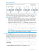
Sample ifconfig output for StoreAll node 2: Figure 3 (page 10) and the corresponding command output illustrate the state of the nodes after the Fusion Manager has migrated from StoreAll node 1 to StoreAll node 2. The only change is the Fusion Manager VIF (bond0:0) is now inactive on StoreAll node 1 and active on StoreAll node 2.
The cluster in Figure 3 (page 10), shows FM failover from StoreAll node 1 to StoreAll node 2: • StoreAll node 1 is servicing file client requests to 10.30.214.202 (StoreAll node 1–bond0:2). • StoreAll node 2 is servicing file client requests to 10.30.214.203 (StoreAll node 2–bond0:2). • Fusion Manager is active on StoreAll node 2, accepting requests to 10.30.214.201 (StoreAll node 1–bond0:0).
Overview of HP StoreAll Storage networking
Sample ifconfig output for StoreAll node 2 after migrating the FM from StoreAll node 1 to StoreAll node 2: User VIF failover To provide high availability to File Clients, HP recommends that StoreAll user networks use VIFs for File Client requests. One node is selected as the primary node for the VIF and File Clients then use this VIF when requesting files. The primary node is usually the node that returns those files.
Example node failover The following example illustrates what occurs when a node is forced to fail over. The example shows a StoreAll 9730 platform in a flat network topology. All IP addresses and other identifiers have been chosen for illustration purposes and could be different on a customer installation. In this example, the cluster starts with two active nodes. StoreAll node 1 has the active Fusion Manager and is serving files from IP address 10.30.214.202.
The ibrix_nic command displays the cluster-wide configuration of the network. Before failing over StoreAll node 1, the output would be similar to the following: To see how this maps onto each node, check the output of the Linux ifconfig command for each node. The ifconfig output shows only the active interfaces. VIFs and failover are handled at the StoreAll solution layer, which dynamically creates and removes the necessary interfaces on the nodes to react to conditions that cause failover.
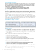
Sample ifconfig output for StoreAll node 1: 16 Overview of HP StoreAll Storage networking
Sample ifconfig output for StoreAll node 2: Figure 5 (page 17) and the corresponding command output illustrate the state of the nodes after StoreAll node 1 has failed and failover has occurred to StoreAll node 2. The Fusion Manager VIF (bond0:0) and the StoreAll node 1 User VIF (bond0:2) have both moved to StoreAll node 2.
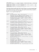
• Server 2 has taken over servicing file client requests to 10.30.214.202 (StoreAll node 2–bond0:3). • Fusion Manager has moved to StoreAll node 2, accepting requests to 10.30.214.201 (StoreAll node 2–bond0:0). After failover, StoreAll node 1 has one active interface and three standby interfaces: • bond0 is the cluster network interface. Notice this does not change during a failover. • bond0:0 is not active. If StoreAll node 1 is recovered, the active Fusion Manager could move back to here.
Output of ifconfig on StoreAll node 1 after failover from StoreAll node 1 to StoreAll node 2: User VIF failover 19
Output of ifconfig on StoreAll node 1 after failover from StoreAll node 1 to StoreAll node 2: Cluster network implications The cluster network’s role in cluster management makes it undesirable to have the same failover characteristics as a user network. Instead, it is important that each node has a unique identity on the cluster network. If a node is degraded and the user network fails over to a backup node, the degraded node can still be monitored and managed using the cluster network.
Table 1 StoreAll nod customer integration features Feature Description Additional user network Beyond the single user VIF that is required to support node failover, StoreAll supports adding VIFs additional user VIFs to an interface. The customer can use this VIF to associate additional IP address ranges with a node. The IP address ranges can then be used to assert control over the network traffic originating from that interface.
In Figure 6 (page 21): • StoreAll node 1 is servicing file client requests to 172.16.116.230 (StoreAll node 1–bond0:2). • StoreAll node 1 is servicing file client requests to 172.16.117.231 (StoreAll node 1–bond0:4). • StoreAll node 2 is servicing file client requests to 172.16.116.231 (StoreAll node 2–bond0:2). • StoreAll node 2 is servicing file client requests to 172.16.117.230 (StoreAll node 2–bond0:4). • Fusion Manager is active on StoreAll node 1, accepting requests to 172.16.115.
Linux networking tools such as ifconfig display a network interface with an associated VLAN tag using a device label with the form bond#.. For example, if the first bond created by StoreAll has a VLAN tag of 30, it will be labeled bond0.30. It is also possible to add a VIF on top of an interface that has an associated VLAN tag. In this case, the device label of the interface takes the form bond#... For example, if a VIF with a label of 2 is added for the bond0.
When operating normally, StoreAll node 1 has four active interfaces and two standby interfaces: Interfaces Network Active Function VLAN VIF bond0.20 Cluster Yes Cluster Network Interface for node 1 Yes (VLAN Tag 20) No bond0.20:0 Cluster Yes Fusion Manager Yes (VLAN Tag 20) Yes (Base: bond0.20) bond0.30 User 1 Yes File Services on VLAN 30 from node 1 Yes (VLAN Tag 30) No bond0.30:2 User 1 No Failover for File Services on VLAN 30 from node 2 Yes (VLAN Tag 30) Yes (Base: bond0.
Appropriate ifconfig output from StoreAll node 1: Appropriate iconfig output from StoreAll node 2: StoreAll node customer integration features 25
Link Aggregation Control Protocol (LACP) trunking Link Aggregation Control Protocol is an IEEE standard that provides a method to control the bundling of several physical interfaces to form a single logical channel. LACP works by sending frames (LACPDUs) down all links that have the protocol enabled.
In addition to the Linux bond trunking implemented primarily for fault-protection, some StoreAll Storage components also support the lower level LACP trunking mechanism to increase the maximum bandwidth available to a network connection. In X9720/9730 systems, LACP support is enabled in the Virtual Connect modules to allow an increase of the maximum bandwidth available between the c7000 enclosure and the customer network.
2 StoreAll 9730 platform networking The StoreAll 9730 platform uses a c7000 enclosure with the following components: • A rack-mounted enclosure frame with a midplane for routing power and signals between the bays in the enclosure. • Bays for two Onboard Administrator modules. • Bays for two Virtual Connect Interconnect modules. • Bays for four 6G SAS switch Interconnect modules. • Bays for up to eight pairs of server blades.
Interconnect Module: Virtual Connect (VC) The virtual connect modules are responsible for configuring and routing all of the network traffic between the enclosure’s servers and the external customer network. The c7000 enclosure dedicates interconnect bays 1 and 2 to the Virtual Connect modules. Two modules in a master-slave relationship are used to achieve path redundancy between the server blades and the external network.
Flat network NOTE: A flat network may also be referred to a unified network. The ASCII Installation Wizard was changed in StoreAll OS v6.5 to use the term “flat network” exclusively. The flat network is the recommended default configuration for StoreAll 9730 networking. This configuration combines the cluster, user, and management networks onto a single IP network. Subnets segregate the management network from the cluster and user networks, while still allowing access for remote management.
Figure 8 StoreAll 9730 flat network — logical view The customer is responsible for establishing the route between the user/cluster subnet and the management subnet. At the logical layer, all node access to the network goes through a bond interface to allow the underlying physical layer to implement multiple pathways to the network. (The next section describes how the bond interfaces map to the underlying physical interfaces.
IP address usage In this configuration, the StoreAll 9730 requires the following IP addresses. Table 4 StoreAll 9730 flat network — IP address usage Component Subnet Minimum number of addresses Maximum number of addresses Nodes user/cluster 2 16 iLO management 16 16 Interconnect management 8 8 OA module management 2 2 FM VIF cluster 1 1 User VIF user 2 Variable.
Figure 9 StoreAll 9730 flat network — physical description The VC modules are cross linked through connectors X7 and X8 to provide redundant paths from the enclosure midplane to the external network. The connection of X7 and X8 is internally implemented on the enclosure midplane. External cables should not be plugged into VC connections X7 and X8. Example of packet traversals This section uses sample packet traversals through the physical connections to illustrate the flow of network traffic.
Procedure 1 1. 2. 3. 4. 5. The packet is created in the application layer of the StoreAll node and is destined for a file client on the user network. The operating system determines by IP address that the user network can be reached through the bond0 interface and queues the packet for that interface. The bond driver determines which of its two underlying physical interfaces are up and functioning correctly.
StoreAll node physical hardware mapping Table 5 (page 35) shows the mapping of the logical networks to the server blade and VC interconnect hardware.
Table 6 StoreAll 9730 flat network — cabling summary Connection Origin Destination Virtual Connect Module 1 Interconnect bay 1 – Connector X6 Customer Edge Switch – User/Cluster subnet Virtual Connect Module 2 Interconnect bay 2 – Connector X6 Customer Edge Switch – User/Cluster subnet Onboard Administrator 1 OA1 – RJ-45 ( Labeled: iLO ) Customer Edge Switch – Management subnet Onboard Administrator 2 OA2 – RJ-45 ( Labeled: iLO ) Customer Edge Switch – Management subnet Increasing external bandwi
Verifying the network configuration Run the following commands on a node to verify and troubleshoot the flat network configuration. Sample output for a correctly configured enclosure is provided. Verify Virtual Connect configuration. Use the vc_config_check.py script to verify the enclosure VC modules are configured as expected: Verify node network interface devices.
Dedicated management network The dedicated management network configuration consists of two distinct networks. One network carries the cluster and user network traffic. A separate network is dedicated to the management network traffic. The dedicated management network is equivalent to the standard IBRIX X9720 configuration, which shipped with dedicated switches for the management network.
Figure 12 StoreAll 9730 dedicated management network — logical view The customer is responsible for establishing any required routes in their network. The StoreAll 9730 cannot set these up automatically. At the logical layer, all node access to the network is done through a bond interface to allow the underlying physical layer to implement multiple pathways to the network. The next section describes how the bond interfaces map to the underlying physical interfaces.
Table 7 StoreAll 9730 dedicated management network — IP address usage Component Subnet Minimum number of addresses Maximum number of addresses Nodes user/cluster 2 16 iLO management 16 16 Interconnect management 8 8 OA module management 2 2 FM VIF cluster 1 1 User VIF user 2 Variable.
Figure 13 StoreAll 9730 dedicated management network — physical view Example of packet traversals This section provides sample packet traversals through the physical connections to illustrate the flow of network traffic. Packet traversing from StoreAll node to external user network: 1. The packet is created in the application layer of the node and is destined for a file client on the user network. 2.
3. 4. 5. The bond driver determines which of its two underlying physical interfaces are up and functioning correctly. If both interfaces are available, the packet is sent out over the last working interface, otherwise it is routed to the working interface. For illustration, assume that the eth1 interface was chosen for transmission to the VC via the enclosure midplane. The VC module in bay 1 receives the packet from the enclosure midplane and determines that it is meant for the external network.
Table 8 StoreAll 9730 dedicated management network — physical mapping Network Node Interface Management Bond0 User, Cluster Bond1 Allocated Bandwidth Node Physical Interface VC Module 1 Gb eth 0 Interconnect Bay 1 X6 Primary External Connection eth 3 Interconnect Bay 2 X6 Primary External Connection eth1 Interconnect Bay 1 X5 Primary External Connection 9 Gb VC External Connection X4, X3, X2, X1 eth 2 Interconnect Bay 2 X5 X4, X3, X2, X1 Connection Type LACP trunking with X5 Primary Ex
Table 9 StoreAll 9730 dedicated management network — cabling summary Connection Origin Destination Virtual Connect Module 1, Management Connection Interconnect bay 1 – Connector X6 Customer Edge Switch – Management network Virtual Connect Module 1, User/Cluster Connection Interconnect bay 1 – Connector X5 Customer Edge Switch – User/Cluster network Virtual Connect Module 2, Management Connection Interconnect bay 2 – Connector X6 Customer Edge Switch – Management network Virtual Connect Module 2,
Verify Virtual Connect configuration. Use the vc_config_check.py script to verify that the enclosure VC modules are configured as expected: [prompt ~]# vc_config_check.py -n2 Looking for credential: chassis:chassis/vc vNet name is correct bond0 vNet name is correct bond1 vNets speeds are correct vNet1 external ports assigned correctly vNet2 external ports assigned correctly Correct number of profiles found (16) Verify node network interface devices.
collisions:0 txqueuelen:1000 RX bytes:2410457366 (2.2 GiB) Memory:f3ea0000-f3ec0000 lo TX bytes:105730002 (100.8 MiB) Link encap:Local Loopback inet addr:127.0.0.1 Mask:255.0.0.0 inet6 addr: ::1/128 Scope:Host UP LOOPBACK RUNNING MTU:16436 Metric:1 RX packets:3510263 errors:0 dropped:0 overruns:0 frame:0 TX packets:3510263 errors:0 dropped:0 overruns:0 carrier:0 collisions:0 txqueuelen:0 RX bytes:522831923 (498.6 MiB) TX bytes:522831923 (498.
Figure 16 StoreAll 9730 additional physical user networks — logical view When correctly configured the following should work: • Nodes should be able to ICMP ping all of the other network attached components, both on the user/cluster subnet and the management subnet. • File Clients should be able to ICMP ping the nodes. • The protocols listed in Table 3 (page 27) must work between the components, and should not be blocked by intervening firewalls or routers.
Table 10 StoreAll 9730 — IP addresses for one additional physical user network (continued) Component Subnet Minimum number of addresses Maximum number of addresses Interconnect management 8 8 OA module management 2 2 FM VIF cluster 1 1 User VIF user 4 Variable.
Figure 17 StoreAll 9730 one additional physical user network — physical view Additional physical user networks 49
Figure 18 StoreAll 9730 two additional physical user networks — physical view StoreAll node physical hardware mapping Table 12 (page 51) shows the mapping of the logical networks to the server blade and VC interconnect hardware for the addition of one physical user network.
Table 12 StoreAll 9730 — mapping for one additional physical user network Network Node Interface Management Bond0 User, Cluster Bond1 Allocated Bandwidth Node Physical Interface VC Module 1 Gb eth 0 Interconnect Bay 1 X6 Primary External Connection eth 3 Interconnect Bay 2 X6 Primary External Connection eth1 Interconnect Bay 1 X3 Primary External Connection 4.5 Gb VC External Connection X2, X1 eth 2 Interconnect Bay 2 X3 X2, X1 User2 Bond2 4.
Physical cabling The minimum cabling required to attach an StoreAll 9730 enclosure with one additional physical user network consists of the eight patch cables shown in Figure 19 (page 52). For maximum redundancy, each patch cable ideally connects to a physically separate edge switch in the customer network.
The 10 patch cables shown in Figure 20 (page 53) are the minimum cabling required to attach an StoreAll 9730 enclosure with two additional physical user networks. For maximum redundancy, each patch cable ideally connects to a physically separate edge switch in the customer network.
Increasing external bandwidth In the additional physical user network configurations, the bond1 and bond2 connections are internally configured to support LACP trunking through the VC. Figure 21 (page 54) and Figure 22 (page 54) illustrate the connections for one and two additional networks. Cables should be added in numerically descending order starting with the highest numbered connection port for a given bond.
3 StoreAll 93xx/8x00 platform networking The StoreAll 93xx/8x00 platform uses discrete servers and storage components to form a storage solution. A minimal 93xx/8x00 installation has the following components: • Two rack mounted servers with expansion cards supporting SAS and high-speed Ethernet connections. • Network manager storage enclosure (MSA, 9320 only) or attached block storage (does not require a network connection).
The flat network is the recommended default configuration for StoreAll 93xx/8x00 networking. This configuration combines the cluster, user, and management networks onto a single IP network. Subnets are used to segregate the management network from the cluster and user networks, while still allowing access for remote management. Modern high-speed networking hardware makes this combination possible without unduly affecting performance.
Figure 23 StoreAll 93xx/8x00 flat network — logical view The customer is responsible for establishing the route between the user/cluster subnet and the management subnet. At the logical layer, all node access to the network is done through a bond interface to allow the underlying physical layer to implement multiple pathways to the network. (The next section describes how the bond interfaces map to the underlying physical interfaces.
Customer use of VLANs or multiple user network VIFs can require additional IP addresses beyond those specified in this table. Management subnet When using the flat configuration, HP recommends that the management network be placed on a separate subnet to limit the amount of non-management traffic that the management interfaces need to process.
4. 5. interface, otherwise it is routed to the working interface. For illustration, assume that the eth4 interface was chosen for transmission. The packet is transmitted out the eth4 connection to the customer edge switch. Packet routing from this switch to the file client is completed within the customer’s network. Packet traversing from node to node: 1. The packet is created in the application layer of StoreAll node 1 and is destined for StoreAll node 2. 2.
Physical cabling The minimum cabling required for attachment of a single StoreAll 93xx/8x00 server to a customer network consists of the three patch cables shown in Figure 25 (page 60). A minimal StoreAll 93xx/8x00 installation has two of these server components. For maximum redundancy, ideally each patch cable is connected to a physically separate edge switch in the customer network.
Figure 26 StoreAll 9320 flat network — MSA (network managed storage) enclosure cabling HP StoreAll 93xx/8x00 6.2 QR-DVD.iso installation network defaults By default, beginning with version 6.2, the StoreAll OS installation will automatically detect a single 10 Gb NIC or dual 10 Gb NICS and place all available NIC ports into Bond0 and configure for default bonding mode 1. There is support for configuring bonding modes 4 or 6 via the F2 Advanced Network Configuration menu during the installation.
Table 19 StoreAll 93xx/8x00 flat network configuration — cabling summary (continued) Connection Origin Destination MSA enclosure, Controller A (9320 only) Rear of MSA enclosure, Upper controller slot, Integrated RJ-45 connector Customer Edge Switch – Management subnet MSA enclosure, Controller B (9320 only) Rear of MSA enclosure, Lower controller slot, Integrated RJ-45 connector Customer Edge Switch – Management subnet Verifying the network configuration Run the following command to verify and trou
Available network topologies The ASCII Installation wizard available in StoreAll OS v6.5 now supports 4 different networking configurations as part of the primary installation flow. These additional network topologies are available if the flat network topology does not meet your needs. NOTE: HP still recommends using the flat (unified) topology as default. Use one of the other topologies only if it better fits your network needs. The network topologies are: • Flat (unified): See “Flat network” (page 55).
4 Expanding an existing cluster When adding a new installation to an existing cluster, HP recommends that the new installation conform to the network topology of the existing cluster. Since earlier StoreAll platforms were often shipped with dedicated ProCurve switches for connecting the management components, this implies that the new system should implement the dedicated management network topology and should use the existing ProCurve switches for its management network.
Figure 28 IBRIX X9720 expansion with 9730 —physical network 65
Figure 29 IBRIX X9720 expansion with 9730 — cabling 66 Expanding an existing cluster
5 Support and other resources Contacting HP For worldwide technical support information, see the HP Support Center: http://www.hp.com/go/hpsc Before contacting HP, collect the following information: • Product model names and numbers • Technical support registration number (if applicable) • Product serial numbers • Error messages • Operating system type and revision level • Detailed questions Related information For related StoreAll documentation, go to the StoreAll Manuals page: http://www.hp.
6 Documentation feedback HP is committed to providing documentation that meets your needs. To help us improve the documentation, send any errors, suggestions, or comments to Documentation Feedback (docsfeedback@hp.com). Include the document title and part number, version number, or the URL when submitting your feedback.
A BOND modes Table 20 BOND mode descriptions Mode Mode Name Mode Description 1 active-backup Active-backup policy: Only one slave in the bond is active. A different slave becomes active if, and only if, the active slave fails. The bond's MAC address is externally visible on only one port (network adapter) to avoid confusing the switch. In bonding version 2.6.2 or later, when a failover occurs in active-backup mode, bonding issues one or more gratuitous ARPs on the newly active slave.
B StoreAll 93xx 10 GbE bonding modes and switch interconnection This appendix discusses supported bond modes versus the connection topology of the customer edge switch. The connections described here are all originating from a single node. Table 20 describes the switch topologies.
C Install and the default Virtual Connect configuration Before an initial install is performed on a c7000 enclosure, its Virtual Connect modules are in the factory default configuration. Table 22 lists the default configuration and its implications for the installer.