
6.2 HP IBRIX 9000 Storage Network Best Practices Guide (TA768-96069, December 2012)

From the point of view of the IBRIX platform, this duplicates many of the capabilities provided by
multiple user VIFs, and VLANs can be used in much the same way as user VIFs. But from the point
of view of the network administrator, VLANs potentially provide a more flexible approach to
managing the network, due to the potential VLAN support already built into the customer’s
intermediate networking infrastructure.
Linux networking tools such as ifconfig display a network interface with an associated VLAN
tag using a device label with the form bond#.<VLAN_id>. For example, if the first bond created
by IBRIX has a VLAN tag of 30, it will be labeled bond0.30.
It is also possible to add a VIF on top of an interface that has an associated VLAN tag. In this case,
the device label of the interface takes the form bond#.<VLAN_id>.<VVIF_label>. For example,
if a VIF with a label of 2 is added for the bond0.30 interface, the new interface device label will
be bond0.30:2.
Cluster/user/management network support
The IBRIX platform supports the use of VLAN tagging on the cluster and user networks. The
management network does not currently support VLAN tagging because some of the embedded
components that could potentially be attached to the management network do not have support
for VLAN tagging.
When operating in the unified network topology with VLAN tagging enabled on the cluster network,
it is the responsibility of the customer route between the cluster/user subnet and the management
subnet to perform the necessary stripping or addition of VLAN tags for packets traversing between
a FSN and a management component.
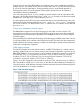
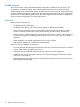
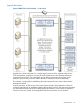
VLAN tagging example
The following example shows the network setup for an IBRIX 9730 platform in a unified network
topology, operating with two user VLANs; however, the principal configuration is the same for all
IBRIX 9000 platforms. File serving nodes 1 and 2 have been configured to serve files to VLAN 30
and VLAN 40. FSN 1 is serving files from IP Address 172.16.116.230 on VLAN 30, and from
IP address 172.16.117.231 on VLAN 40. FSN 2 is serving files from IP address 172.16.116.231
on VLAN 30, and from IP address 172.16.117.230 on VLAN 40.
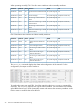
Figure 7 shows the configuration of the interfaces on the two FSNs, which are set up as a failover
pair. The interfaces in bold (bond 0) are active on the FSN; the other interfaces are standbys put
in place for failover. All IP addresses and other identifiers have been chosen for illustration purposes
and could be different on a customer installation.
Figure 7 FSN with VLAN tagging
FSN customer integration features 21