
6.2 HP IBRIX 9000 Storage Network Best Practices Guide (TA768-96069, December 2012)
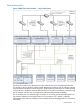
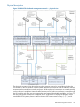
Example of packet traversals
This section uses sample packet traversals through the physical connections to illustrate the flow of
network traffic.
Packet traversing from FSN to external user network:
1. The packet is created in the application layer of the FSN and is destined for a file client on
the user network.
2. The O/S determines by IP address that the user network can be reached through the bond0
interface and queues the packet for that interface.
3. The bond driver determines which of its two underlying physical interfaces are up and
functioning correctly. If both interfaces are available, the driver sends the packet out the last
working interface, otherwise it routes the packet to the working interface. For illustration,
assume that the eth0 interface was chosen for transmission to the VC via the enclosure
midplane.
4. The VC module in bay 1 receives the packet from the enclosure midplane and determines that
it is meant for the external network. It forwards the packet out the X6 connector (or one of the
other LACP trunked connectors), to the customer network via the customer’s edge switch.
5. Packet routing from this switch to the file client is completed within the customer’s network.
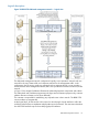
Packet traversing from FSN to FSN:
1. The packet is created in the application layer of FSN (bay 1) and is destined for FSN (bay
2).
2. The O/S determines by IP address that FSN (bay 2) can be reached through the bond0
interface and queues the packet for that interface.
3. The bond driver determines which of its two underlying physical interfaces to use. For
illustration, assume that the eth3 interface was chosen for transmission to the VC via the
enclosure midplane.
4. The VC module in bay 2 receives the packet from the enclosure midplane and determines that
it is meant for another server in the same enclosure. It forwards the packet via the enclosure
midplane to the eth3 interface of FSN (bay 2).
5. The FSN (bay 2) eth3 physical interface receives the packet from the enclosure midplane.
Since eth3 is a member of bond0, the packet is forwarded to the bond driver for routing to
the application layer.
6. The application layer on FSN (bay 2) receives the packet from the bond0 interface.
Packet traversing from FSN to management network:
1. The packet is created in the application layer of the FSN and is destined for the management
interface of one of the enclosure's SAS interconnect modules.
2. The O/S determines by IP address that the management network can be reached through the
bond0 interface and queues the packet for that interface.
3. The bond driver determines which of its two underlying physical interfaces should be used to
transmit the packet. For illustration, assume that the eth0 interface was chosen for transmission
to the VC via the enclosure midplane.
4. The VC module in bay 1 receives the packet from the enclosure midplane and determines that
it should be routed through the external network. It forwards the packet out the X6 connector
(or one of the other LACP trunked connectors), to the customer network via the customer’s
edge switch.
5. The packet is routed through the customer’s network to the edge switch connected to the
enclosure's active OA module.
6. The OA determines that the packet needs to be routed to the enclosure's SAS interconnect. It
forwards the packet via the enclosure midplane to the management interface on the target
SAS interconnect.
7. The embedded system on the SAS interconnect module receives and processes the packet.
32 IBRIX 9730 platform networking