
6.2 HP IBRIX 9000 Storage Network Best Practices Guide (TA768-96069, December 2012)
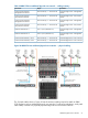
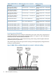
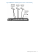
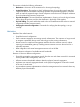
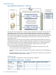
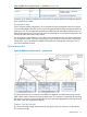

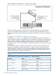

Table 14 IBRIX 9730 one additional physical user network — cabling summary
DestinationOriginConnection
Customer Edge Switch – Management
network
Interconnect bay 1 – Connector X6Virtual Connect Module 1,
Management Connection
Customer Edge Switch – User/Cluster
network
Interconnect bay 1 – Connector X3Virtual Connect Module 1,
User/Cluster Connection
Customer Edge Switch – Management
network
Interconnect bay 2 – Connector X6Virtual Connect Module 2,
Management Connection
Customer Edge Switch – User/Cluster
network
Interconnect bay 1 – Connector X3Virtual Connect Module 2,
User/Cluster Connection
Customer Edge Switch – Management
network
OA1 – RJ-45 ( Labeled: iLO )Onboard Administrator 1
Customer Edge Switch – Management
network
OA2 – RJ-45 ( Labeled: iLO )Onboard Administrator 2
Customer Edge Switch – User 2 networkInterconnect bay 1 – Connector X5Virtual Connect Module 1, User 2
Customer Edge Switch – User 2 networkInterconnect bay 1 – Connector X5Virtual Connect Module 2, User 2
Figure 20 IBRIX 9730 two additional physical user networks — physical cabling
The 10 patch cables shown in Figure 20 are the minimum cabling required to attach an IBRIX
9730 enclosure with two additional physical user networks. For maximum redundancy, each patch
cable ideally connects to a physically separate edge switch in the customer network.
Additional physical user networks 51