
6.2 HP IBRIX 9000 Storage Network Best Practices Guide (TA768-96069, December 2012)
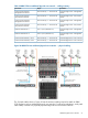
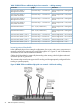
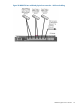
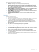
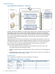
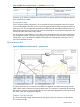
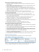

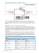

Table 15 IBRIX 9730 two additional physical user networks — cabling summary
DestinationOriginConnection
Customer Edge Switch – Management
network
Interconnect bay 1 – Connector X6Virtual Connect Module 1,
Management Connection
Customer Edge Switch – User/Cluster
network
Interconnect bay 1 – Connector X2Virtual Connect Module 1,
User/Cluster Connection
Customer Edge Switch – Management
network
Interconnect bay 2 – Connector X6Virtual Connect Module 2,
Management Connection
Customer Edge Switch – User/Cluster
network
Interconnect bay 1 – Connector X2Virtual Connect Module 2,
User/Cluster Connection
Customer Edge Switch – Management
network
OA1 – RJ-45 ( Labeled: iLO )Onboard Administrator 1
Customer Edge Switch – Management
network
OA2 – RJ-45 ( Labeled: iLO )Onboard Administrator 2
Customer Edge Switch – User 2 networkInterconnect bay 1 – Connector X4Virtual Connect Module 1, User 2
Customer Edge Switch – User 2 networkInterconnect bay 2– Connector X4Virtual Connect Module 2, User 2
Customer Edge Switch – User 3Interconnect bay 1 – Connector X5Virtual Connect Module 1, User 3
Customer Edge Switch – User 3Interconnect bay 2 – Connector X5Virtual Connect Module 2, User 3
Increasing external bandwidth
In the additional physical user network configurations, the bond1 and bond2 connections are
internally configured to support LACP trunking through the VC. Figures 21 and 22 illustrate the
connections for one and two additional networks.
Cables should be added in numerically descending order starting with the highest numbered
connection port for a given bond.
The customer edge switch must support LACP trunking and be appropriately configured for the
trunking to operate properly.
Figure 21 IBRIX 9730 one additional physical user network – LACP trunk cabling
52 IBRIX 9730 platform networking