
6.2 HP IBRIX 9000 Storage Network Best Practices Guide (TA768-96069, December 2012)


Logical description
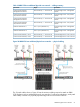
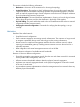
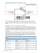
Figure 23 IBRIX 93xx unified network — logical view
Logically, the unified configuration is a single, large IP network with a separate subnet for the 93xx
management components. In Figure 23, the example IP addresses were chosen to illustrate the
relationship between components and subnets. The subnet mask and IP address assignments shown
here are for illustration purposes only. Customer address allocation schemes can be done differently.
The customer is responsible for establishing the route between the user/cluster subnet and the
management subnet.
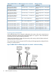
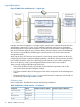
At the logical layer, all FSN access to the network is done through a bond interface to allow the
underlying physical layer to implement multiple pathways to the network. (The next section describes
how the bond interfaces map to the underlying physical interfaces.) In the unified configuration,
all access to the user, cluster, and management networks traverses the bond0 interface.
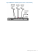
When correctly configured the following should work:
• FSNs should be able to ICMP ping all other network attached components, both on the
user/cluster subnet and the management subnet.
• File Clients should be able to ICMP ping the FSNs and the components on the mManagement
subnet.
• The protocols listed in Table 3 (page 25) must work between the components, and should not
be blocked by intervening firewalls or routers.
IP address usage
In this configuration, the IBRIX 93xx requires the following IP addresses.
Table 16 IBRIX 93xx unified network — IP addresses
Maximum number of addressesMinimum number of addressesSubnetComponent
22user/clusterFile serving nodes
22managementiLO
22managementMSA enclosure
11clusterFM VIF
56 IBRIX 93xx platform networking