
6.2 HP IBRIX 9000 Storage Network Best Practices Guide (TA768-96069, December 2012)
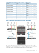
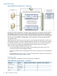

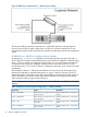

Packet traversing from FSN to external user network:
1. The packet is created in the application layer of the FSN and is destined for a file client on
the user network.
2. The O/S determines by IP address that the user network can be reached through the bond0
interface and queues the packet for that interface.
3. The bond driver determines which of its two underlying physical interfaces are up and
functioning correctly. If both interfaces are available, the packet is sent out the last working
interface, otherwise it is routed to the working interface. For illustration, assume that the eth4
interface was chosen for transmission.
4. The packet is transmitted out the eth4 connection to the customer edge switch.
5. Packet routing from this switch to the file client is completed within the customer’s network.
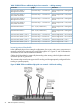
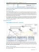
Packet traversing from FSN to FSN:
1. The packet is created in the application layer of FSN 1 and is destined for FSN 2.
2. The O/S determines by IP address that FSN 2 can be reached through the bond0 interface
and queues the packet for that interface.
3. The bond driver determines which of its two underlying physical interfaces to use. For
illustration, assume that the eth5 (FSN 1) interface was chosen for transmission.
4. The packet is transmitted out eth5 (FSN 1) to the customer edge switch.
5. The switch determines that the destination is out one of its other ports, and forwards the packet
to the port that is connected to eth5 (FSN 2).
6. FSN 2 receives the packet on eth5 and passes it to the bond 0 driver.
7. The application layer on FSN 2 receives the packet from the bond0 interface.
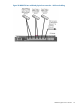
Packet traversing from FSN to management network:
1. The packet is created in the application layer of the FSN and is destined for the management
interface of channel-A in the MSA SAS enclosure.
2. The O/S determines by IP address that the management network can be reached through the
bond0 interface and queues the packet for that interface.
3. The bond driver determines which of its two underlying physical interfaces should be used to
transmit the packet. For illustration, assume that the eth4 interface was chosen for transmission.
4. The packet is transmitted from eth4 to the customer edge switch.
5. The packet is routed through the customer’s network to the edge switch connected to the MSA
enclosure's channel-A management interface.
6. The embedded system on the MSA SAS controller receives and processes the packet.
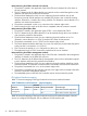
FSN physical hardware mapping
Table 17 shows the mapping of the logical networks to the server interface hardware.
Table 17 IBRIX 93xx unified network — physical mapping
Connection TypeFSN Physical Interface
Allocated
BandwidthFSN InterfaceNetwork
Patch cable to customer edge switcheth 410 GbBond0User, cluster,
management
Patch cable to customer edge switcheth 5
Table 18 shows the mapping of the logical networks to the server interface hardware when the
servers are configured and shipped with an additional 10 Gb interface card.
58 IBRIX 93xx platform networking