
6.2 HP IBRIX 9000 Storage Network Best Practices Guide (TA768-96069, December 2012)


B IBRIX 93xx 10 GbE bonding modes and switch
interconnection
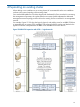
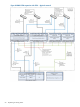
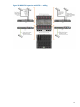
This appendix discusses supported bond modes versus the connection topology of the customer
edge switch. The connections described here are all originating from a single file serving node.
Table 20 describes the switch topologies.
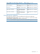
Table 21 Switch topology
DescriptionSwitch Topology
Connect the 2 x 10 GbE ports of the same node to a single switchSingle
Connect the 2 x 10 GbE ports of the same node to 2 switches interconnected with an ISLISL
Connect the 2 x 10 GbE ports of the same node to 2 switches configured as a stackStacked
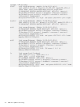
Table 21 summarizes the behavior of the FSN for various bonding modes given a specific customer
switch topology.
Table 22 Bond modes and switch topology
DescriptionSwitch TopologyBond
Mode
Supported. If the single switch goes down, a node failover will occur. For redundancy,
the failover partner must be connected to another switch.
Single1
Supported. Care must be exercised because the ISL could get very busy and become
a bottleneck. You cannot guarantee traffic will stay on the switch rather than going
over the ISL.
ISL1
Supported. This is a preferred setup compared to ISL connected switches, as the stack
links are faster and more intelligent.
Stack1
Supported. If the single switch goes down, a node failover will occur. For redundancy,
the failover partner must be connected to another switch.
Single4
Not Supported. Will not work.ISL4
Supported. This is the preferred configuration. If the stacked switching infrastructure
can create a LACP bond across two switches in a stack configuration, this topology
provides the maximum available bandwidth to the node.
Stack4
69