
HP XC System Software Hardware Preparation Guide Version 3.1
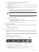


3. Connections to node administration ports start at port 21 (descending).
4. Port 22 is used for the administration port of the head node.
5. Dual personality ports.
6. Port 24 is used as the interconnect to the Root Console Switch (a ProCurve 2650 or ProCurve 2626
model switch).
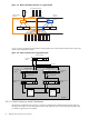
As a result of performance considerations and given the number of ports available in the ProCurve 2824
switch, the allocation order of ports is:
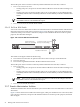
• Ports 1–10, 13–21
— Starting with port 1, the ports are used for links from Branch Administration Switches which
can include the use of trunking. For example, if two port trunking is used, the first Branch
Administration Switch uses port 1 and 2 of the Root Administration Switch.
NOTE: Trunking is restricted to within the same group of 10 (you cannot trunk with ports 10
and 13). HP recommends that all trunking use consecutive ports within the same group (1–10
or 13–21).
— Starting with port 21 and descending, ports are assigned for use by individual root nodes. A
root node is a node that is connected directly to the Root Administration Switch.
• Ports 11 and 12 are unused.
• Port 23 can be one of the following:
— Console (or line monitoring card) for the interconnect
— Connection to the Interconnect Ethernet Switch (IES), which connects to the management port
of multiple interconnect switches.
• Port 24 is used as the interconnect to the Root Console Switch
2.3.6 Root Console Switches
The following switches are supported as Root Console Switches for the Console Branch of the Administration
Network:
• “ProCurve 2650 Switch” (page 25)
• “ProCurve 2626 Switch” (page 26)
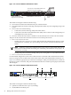
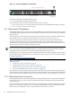
2.3.6.1 ProCurve 2650 Switch
You can use a ProCurve 2650 switch as a Root Console Switch for the Console Branch of the Administration
Network. The Console Branch functions at a lower speed (10/100 Mbps) than the rest of the Administration
Network.
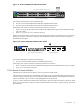
The ProCurve 2650 switch is shown in Figure 2-7. In the figure, white ports should not have connections,
black ports can have connections, and ports with numbered callouts are used for specific purposes, described
after the figure.
Figure 2-7 ProCurve 2650 Root Console Switch
Po rt
LED
Vi
ew
Sel
f
Te
st
Cl
ea r
Re
se t
Fa
n
Statu s
4
5
48
47
46
45
43
4442
41
40
39
38
37
36
35
34
33
32
31
30
29
28
27
26
25
24
23
22
21
20
19
18
17
16
15
14
13
12
11
10
9
8
7
6
Spd mode : of f = 1 0 Mbp s , fl a sh = 1 0 0 M bps , on = 1 0 0 0 Mbps
10/1 00Ba se
-T X Po rt s ( 1 - 48 )
Gi
g- T
Po
rts
Mi
ni -
GB
IC
Po
rts
1 15 17
16
18
31
32
33
34
47
48
50
49
T
M
T
M
Po w er
Fa
ul t
hp pr oc ur ve
swi tch
26 5 0
J4 8 9 9 A
Us
e o nly o ne ( T o r M) f or ea c h G ig abit po r t
!
1
2
3
Spd
Ln k
Ac
t
FD x
10/100Base-TX RJ-45 Ports
Uplinks from Branches
Start at Port 1 (Ascending)
Connections to Node Console Ports
Start at Port 41 (Descending)
Gigabit
Ethernet Ports
The callouts in the figure enumerate the following:
1. Port 42 must be reserved for an optional connection to the console port on the head node.
2. Port 49 is reserved.
3. Port 50 is the Gigabit Ethernet link to the Root Administration Switch.
2.3 Switches 25