
HP XC System Software Hardware Preparation Guide Version 3.1
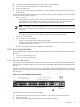


Allocate the ports on this switch for consistency with the administration switches, as follows:
• Ports 1–10, 13–22, 25–34, 37–41
— Starting with port 1, the ports are used for links from Branch Console Switches. Trunking is not
used.
— Starting with port 41 and in descending order, ports are assigned for use by individual nodes
in the utility cabinet. Nodes in the utility cabinet are connected directly to the Root Administration
Switch.
NOTE: There must be at least one idle port in this set to indicate the dividing line between
branch links and root node administration ports.
• Ports 11, 12, 23, 24, 35, 36, and 43–48 are unused.
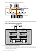
2.3.6.2 ProCurve 2626 Switch
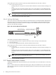
You can use a ProCurve 2626 switch as a Root Console Switch for the Console Branch of the Administration
Network. The ProCurve 2626 switch is shown in Figure 2-8. In the figure, white ports should not have
connections, black ports can have connections, and ports with numbered callouts are used for specific
purposes, described after the figure.
Figure 2-8 ProCurve 2626 Root Console Switch
Pow er
Faul t
hp procurve
sw
itch 262 6
J4900A
Lnk
Ac
t
FD
x
Sp
d
Fan
St
atus
Se
lf
Te
st
Reset Clear
LED
Mode
off = 10MbpsSpd Mode fl ash = 100Mb ps on = 1000Mbps
1
2
3
4
5
6
7
8
9
10
11
12
13
14
15
16
17
18
19
20
21
22
23
24
T
25
M
T
26
M
Use only one (T or M) for Gigabit port
Gig-T
Po
rts
Mini-
GB
IC
Po
rts
Connections to Node Console Ports
Start at port 21 (Descending)
10/100Base-TX RJ-45 Ports
Gigabit
Ethernet
Ports
Uplinks from Branches
Start at port 1 (Ascending)
The callouts in the figure enumerate the following:
1. Port 22 must be reserved for an optional connection to the console port on the head node.
2. Port 25 is reserved.
3. Port 26 is the Gigabit Ethernet link to the Root Administration Switch.
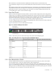
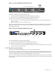
Allocate the ports on this switch for consistency with the administration switches, as follows:
• Ports 1–10, 13–21
— Starting with port 1, the ports are used for links from Branch Console Switches. Trunking is not
used.
— Starting with port 21 and in descending order, ports are assigned for use by individual nodes
in the utility cabinet. Nodes in the utility cabinet are connected directly to the Root Administration
Switch.
NOTE: There must be at least one idle port in this set to indicate the dividing line between
branch links and root node administration ports.
• Ports 11, 12, 23, and 24, are unused.
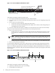
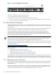
2.3.7 Branch Administration Switches
The Branch Administration Switch of an HP XC system can be either a ProCurve 2848 switch or a ProCurve
2824 switch.
Figure 2-9 shows the ProCurve 2848 switch. In the figure, white ports should not have connections, black
ports can have connections, and ports with numbered callouts are used for specific purposes, described
after the figure.
26 Making Node and Switch Connections