
HP XC System Software Hardware Preparation Guide Version 3.1
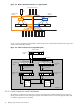
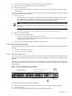
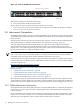


Figure 2-11 ProCurve 2650 Branch Console Switch
Po rt
LED
Vi
ew
Sel
f
Te
st
Cl
ea r
Re
se t
Fa
n
Statu
s
4
5
48
47
46
4543
4442
41
40
39
38
37
36
35
34
33
32
31
30
29
28
27
26
25
24
23
22
21
20
19
18
17
16
15
14
13
12
11
10
9
8
7
6
Spd mode : of f = 1 0 Mbp s , fl a sh = 1 0 0 M bps , on = 1 0 0 0 Mbps
10/100 Ba se
-T X Po rt s ( 1 - 48 )
Gi
g- T
Po
rts
Mi
ni -
GB
IC
Po rts
1 15 17
16
18
31
32
33
34
47
48
50
49
T
M
T
M
Po w er
Fa
ul t
hp pr oc ur ve
swi tch
26 5 0
J4 8 9 9 A
Us
e o nly o ne ( T o r M) f or ea c h G ig abit po r t
!
1
2
3
Spd
Ln k
Ac
t
FD x
10/100Base-TX RJ-45 Ports
Connections to Node Console Ports
Gigabit
Ethernet Ports
The callout in the figure enumerates the following:
1. Port 50 is the link to the Root Console Switch.
Allocate the ports on this switch for maximum performance, as follows:
• Ports 1–10, 13–22, 25–34, 37–44 are used for the console ports of individual nodes (up to 38 nodes).
• Ports 11, 12, 23, 24, 35, 36, 45–49 are unused
2.4 Interconnect Connections
The high-speed interconnect connects every node in the HP XC system. Each node can have an interconnect
card installed in the highest speed PCI-X slot (133 Mhz). Check the hardware documentation to determine
which slot this is.
The interconnect switch console port (or monitoring line card) also connects to the Root Administration
Switch either directly or indirectly, as described in “Root Administration Switch” (page 23).
You must determine the absolute maximum number of nodes that could possibly be used with the
interconnect hardware that you have. This maximum number of ports on the interconnect switch or
switches (max-node) affects the naming of the nodes in the system. The documentation that came with
the interconnect hardware can help you find this number.
NOTE: You can choose a number smaller than the absolute maximum number of interconnect ports for
max-node, but you can not expand the system to a size larger than this number in the future without
completely rediscovering the system, thereby renumbering all nodes in the system.
This restriction does not apply to hardware configurations that contain HP server blades and enclosures.
For more information, see the HP XC Systems With HP Server Blades and Enclosures HowTo, which is available
at the following Web site:
http://www.docs.hp.com/en/highperfcomp.html
Specific considerations for connections to the interconnect based on interconnect type are discussed in the
following sections:
• “QsNet Interconnect Connections” (page 28)
• “Gigabit Ethernet Interconnect Connections” (page 29)
• “Administration Network Interconnect Connections” (page 29)
• “Myrinet and InfiniBand Interconnect Connections” (page 29)
The method for wiring the Administration Network and interconnect networks allows expansion of the
system within the system's initial interconnect fabric without recabling of any existing nodes. If additional
switch chassis or ports are added to the system as part of the expansion, some recabling may be necessary.
2.4.1 QsNet Interconnect Connections
For the QsNet
II
interconnect developed by Quadrics, it is important that nodes are connected to the Quadrics
switch ports in a specific order. The order is affected by the order of the Administration Network and
Console Network.
Because the Quadrics port numbers start numbering at 0, the highest port number on the Quadrics switch
is port max-node minus 1, where max-node is the maximum number of nodes possible in the system.
This is the port on the Quadrics switch to which the head node must be connected.
28 Making Node and Switch Connections