
HP XC System Software Hardware Preparation Guide Version 3.1
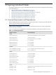
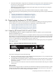
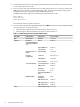
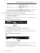
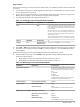
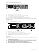
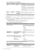

Table 3-4 BIOS Settings for HP ProLiant DL140 G3 Nodes (continued)
Set To This ValueOption NameSubmenu NameMenu Name
Enabled
Embedded NIC1 PXE
Disabled
Embedded NIC2 PXE
Off
Resume On Modem
Ring
Power
Disabled
Wake On LAN
4. From the Main window, select Exit → Save Changes and Exit to exit the utility.
5. Repeat this procedure for every HP ProLiant DL140 G2 and G3 node in the HP XC system.
3.4.2 Preparing HP ProLiant DL360 G4 and G5 Nodes
Use the following tools to configure the appropriate settings for HP ProLiant DL360 G4 and G5 servers
• Integrated Lights Out (iLO) Setup Utility
• ROM-Based Setup Utility (RBSU)
Figure 3-2 shows a rear view of the HP ProLiant DL360 G4 server and the appropriate port assignments
for an HP XC system.
Figure 3-2 HP ProLiant DL360 G4 Server Rear View
11
The callouts in the figure enumerate the following:
1. The iLO Ethernet is the port used as the connection to the Console Switch.
2. NIC1 is used for the connection to the Administration Switch (branch or root).
3. NIC2 is used for the external connection.
Figure 3-3 shows a rear view of the HP ProLiant DL360 G5 server and the appropriate port assignments
for an HP XC system.
Figure 3-3 HP ProLiant DL360 G5 Server Rear View
3
2
1
The callouts in the figure enumerate the following:
1. This port is used for the connection to the Console Switch.NIC1 is used for the connection to the
Administration Switch (branch or root).
2. This port is used for the connection to the Administration Switch (branch or root).
3. The second onboard NIC is used for the Gigabit Ethernet interconnect or is used for the connection
to the external network.
36 Preparing Individual Nodes