HP ProLiant DL580 Generation 5 Server User Guide Part Number 453878-002 September 2008 (Second Edition)
© Copyright 2007 Hewlett-Packard Development Company, L.P. The information contained herein is subject to change without notice. The only warranties for HP products and services are set forth in the express warranty statements accompanying such products and services. Nothing herein should be construed as constituting an additional warranty. HP shall not be liable for technical or editorial errors or omissions contained herein. Microsoft, Windows, Windows Server 2003, and Windows NT are U.S.
Contents Component identification ............................................................................................................... 7 Front panel components ............................................................................................................................. 7 Front panel LEDs and buttons ...................................................................................................................... 8 Systems Insight Display ......................................
Memory options ...................................................................................................................................... 39 Memory configurations................................................................................................................... 39 Advanced ECC memory ................................................................................................................. 40 Online spare memory configuration ................................................
Integrated Management Log ........................................................................................................... 73 Array Diagnostic Utility .................................................................................................................. 73 Remote support and analysis tools ............................................................................................................. 73 HP Instant Support Enterprise Edition................................................
Server specifications ................................................................................................................................ 98 Technical support...................................................................................................................... 100 Before you contact HP............................................................................................................................ 100 HP contact information ............................................
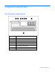
Component identification Front panel components Item Description 1 USB connectors 2 Video connector 3 Systems Insight Display 4 DVD drive bay 5 Optional tape drive or blank 6 Optional hard drive bay or blank 7 Hard drive bay 8 Processor memory module Component identification 7
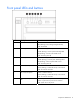
Front panel LEDs and buttons Item Description Status 1 UID switch and LED Blue—Activated Blue (flashing)—Server being managed remotely Off—Deactivated 2 Internal system health LED Green—Normal (system on) Amber (flashing)—Internal system health degraded Red (flashing)—Internal system health critical Off—Normal (system off) 3 External system health LED Green—Normal (system on) Amber (flashing)—External system health degraded Red (flashing)—External system health critical Off—Normal (system off)
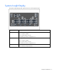
Systems Insight Display The Systems Insight Display LEDs represent the server and component layout.
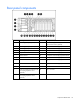
Rear panel components Item Description Item Description 1 Power supply bay 4 (optional) 13 PCI-X non-hot-plug for PCI Express x8 non-hotplug expansion slot 3 (optional) 2 Power supply bay 3 (optional) 14 PCI Express x8 non-hot-plug expansion slot 4 3 Power supply bay 2 15 PCI Express x8 non-hot-plug expansion slot 5 4 Power supply bay 1 16 PCI Express x8 non-hot-plug expansion slot 6 5 Keyboard connector 17 PCI Express x8 non-hot-plug expansion slot 7 6 USB connectors 18 PCI Expr
Rear panel LEDs and buttons Item Description LED color Status 1 NIC 2 Activity LED Green On or flashing—Network activity Off—No network activity 2 NIC 2 Link LED Green On—Linked to network Off—Not linked to network 3 UID Blue On—Front UID button activated Off—Normal 4 iLO 2 NIC Activity LED Green On or flashing—Network activity Off—No network activity 5 iLO 2 NIC Link LED Green On—Linked to network Off—Not linked to network 6 NIC 1 Link LED Green On—Linked to network Off—Not link
Power supply LED Power LED (green) Failure LED (amber) Status Off Off No AC power to power supply units On Off AC present. Standby output on.
System board components Item Description 1 Fan 1 2 Fan 2 3 Connector for: • PCI Express x8 3 Slot Option Card (optional) • PCI-X 3 Slot Option Card (optional) 4 Fan 3 5 Fan 5 6 Fan 4 7 Fan 6 8 PCI Express x8 non-hot-plug expansion slot 4 9 PCI Express x8 non-hot-plug expansion slot 5 10 PCI Express x8 non-hot-plug expansion slot 6 11 PCI Express x8 non-hot-plug expansion slot 7 12 PCI Express x4 non-hot-plug expansion slot 8 13 PCI Express x4 non-hot-plug expansion slot 9 14
Item Description 16 System maintenance switch 17 SPI board SPI board components Item Description 1 BBWC cache module connectors 2 Battery System maintenance switch The system maintenance switch (SW1) is an eight-position switch that is used for system configuration. The default position for all eight positions is Off.
Position Description Function S6 Invalidate configuration Off = Normal S7 Reserved Reserved S8 Reserved Reserved On = Clears NVRAM FBDIMM slot locations The server contains 16 FBDIMM slots on the processor-memory board, which are numbered sequentially from 1 to 16. The paired banks are identified by the letters A through H. Four FBDIMM slots located on each optional memory board are numbered from 1 to 4. The paired banks are identified by the letters A through D.
SAS device numbers Component identification 16
SAS hard drive LEDs Item Description 1 Fault/UID LED (amber/blue) 2 Online LED (green) SAS hard drive LED combinations Online/activity LED (green) Fault/UID LED (amber/blue) On, off, or flashing Alternating amber and The drive has failed, or a predictive failure alert has been blue received for this drive; it also has been selected by a management application. On, off, or flashing Steadily blue The drive is operating normally, and it has been selected by a management application.
Online/activity LED (green) Fault/UID LED (amber/blue) Interpretation Flashing irregularly Off The drive is active, and it is operating normally. Off Steadily amber A critical fault condition has been identified for this drive, and the controller has placed it offline. Replace the drive as soon as possible. Off Amber, flashing regularly (1 Hz) A predictive failure alert has been received for this drive. Replace the drive as soon as possible.
LED3 pattern LED4 pattern Interpretation — One blink every two seconds The system is powered down, and the cache contains data that has not yet been written to the drives. Restore system power as soon as possible to prevent data loss. Data preservation time is extended any time that 3.3 V auxiliary power is available, as indicated by LED 2. In the absence of auxiliary power, battery power alone preserves the data. A fullycharged battery can normally preserve data for at least two days.
Fan locations Component identification 20
Operations Power up the server To power up the server, press the Power On/Standby button. Power down the server WARNING: To reduce the risk of personal injury, electric shock, or damage to the equipment, remove the power cord to remove power from the server. The front panel Power On/Standby button does not completely shut off system power. Portions of the power supply and some internal circuitry remain active until AC power is removed.
• Hard drives • Systems Insight Display WARNING: To reduce the risk of personal injury or equipment damage, be sure that the rack is adequately stabilized before extending a component from the rack. WARNING: To reduce the risk of personal injury, be careful when pressing the server railrelease latches and sliding the server into the rack. The sliding rails could pinch your fingers. To extend the server from the rack: 1.
Removing the access panel WARNING: To reduce the risk of personal injury from hot surfaces, allow the drives and the internal system components to cool before touching them. CAUTION: Do not operate the server for long periods with the access panel open or removed. Operating the server in this manner results in improper airflow and improper cooling that can lead to thermal damage. 1. Extend the server from the rack, if applicable ("Extending the server from the rack" on page 21). 2.
Accessing the Systems Insight Display To access the Systems Insight Display: 1. Press and release the panel. 2. After the display fully ejects, rotate the display downward to view the LEDs. Removing the system battery If the server no longer automatically displays the correct date and time, you may need to replace the battery that provides power to the real-time clock. Under normal use, battery life is 5 to 10 years.
4. If the bracket is installed, remove the bracket. 5. Locate the battery ("SPI board components" on page 14). 6. Remove the battery. To replace the component, reverse the removal procedure. Run the RBSU to configure the server after replacing the battery. See the HP ROM-Based Setup Utility User Guide on the Documentation CD for more detailed information.
Setup Optional installation services Delivered by experienced, certified engineers, HP Care Pack services help you keep your servers up and running with support packages tailored specifically for HP ProLiant systems. HP Care Packs let you integrate both hardware and software support into a single package. A number of service level options are available to meet your needs.
Optimum environment When installing the server, select a location that meets the environmental standards described in this section. Space and airflow requirements To allow for servicing and adequate airflow, observe the following space and airflow requirements when deciding where to install a rack: • Leave a minimum clearance of 63.5 cm (25 in) in front of the rack. • Leave a minimum clearance of 76.2 cm (30 in) behind the rack. • Leave a minimum clearance of 121.
The maximum recommended ambient operating temperature (TMRA) for most server products is 35°C (95°F). The temperature in the room where the rack is located must not exceed 35°C (95°F). CAUTION: To reduce the risk of damage to the equipment when installing third-party options: • Do not permit optional equipment to impede airflow around the server or to increase the internal rack temperature beyond the maximum allowable limits. • Do not exceed the manufacturer’s TMRA.
Rack warnings WARNING: To reduce the risk of personal injury or damage to the equipment, be sure that: • The leveling jacks are extended to the floor. • The full weight of the rack rests on the leveling jacks. • The stabilizing feet are attached to the rack if it is a single-rack installation. • The racks are coupled together in multiple-rack installations. • Only one component is extended at a time. A rack may become unstable if more than one component is extended for any reason.
Setting up a tower model server Follow these steps to set up a tower model server. If you are going to install the server into a rack, see the rack installation section ("Installing the server into the rack" on page 31). 1. Connect the peripheral devices to the server.
Item Description Item Description 9 iLO 2 NIC connector 21 PCI Express x4 non-hot-plug expansion slot 11 10 Mouse connector 22 NIC 2 connector 11 PCI-X non-hot-plug or PCI Express x8 23 non-hot-plug expansion slot 1 (optional) NIC 1 connector 12 PCI-X non-hot-plug or PCI Express x8 24 non-hot-plug expansion slot 2 (optional) T-15 Torx tool WARNING: To reduce the risk of electric shock or damage to the equipment: • Do not disable the power cord grounding plug.
Installing the operating system To operate properly, the server must have a supported operating system. For the latest information on supported operating systems, refer to the HP website (http://www.hp.com/go/supportos). Two methods are available to install an operating system on the server: • SmartStart assisted installation—Insert the SmartStart CD into the CD-ROM drive and reboot the server. • Manual installation—Insert the operating system CD into the CD-ROM drive and reboot the server.
Hardware options installation Introduction If more than one option is being installed, read the installation instructions for all the hardware options and identify similar steps to streamline the installation process. WARNING: To reduce the risk of personal injury from hot surfaces, allow the drives and the internal system components to cool before touching them. CAUTION: To prevent damage to electrical components, properly ground the server before beginning any installation procedure.
2. If the shipping screws are installed, remove them. The shipping screw locations are marked with tags on both sides of the server for easy identification. 3. Release the latches on the lever. 4. Lower the handle, and pull the processor memory module out of the server until the release latches catch.
5. Firmly holding the processor memory module, press the release buttons and pull the module out of the server. 6. Remove the processor memory module cover. To install the processor memory module, reverse the removal steps. Installing a processor 1. Locate and download the latest ROM version from the HP website (http://h18023.www1.hp.com/support/files/server/us/romflash.html). Follow the instructions on the website to update the system ROM. 2. Power down the server (on page 21). 3.
4. Unlock the processor retaining bracket. 5. Open the processor retaining bracket. 6. Open the processor locking lever.
7. Align the guide pins on the base of the processor retaining bracket to the three corresponding guide slots on the processor assembly. 8. Insert the processor assembly into the processor socket, and close the locking lever. CAUTION: To prevent possible server malfunction or damage to the equipment, be sure to completely close the processor locking lever.
9. Close and lock the processor retaining bracket.
10. Install the PPM. NOTE: The appearance of compatible PPMs may vary. 11. Replace the processor memory module cover. 12. Install the processor memory module into the server. 13. Power up the server (on page 21). Memory options This server contains 16 FBDIMM slots on the processor-memory board. You can expand server memory by installing supported registered DDR-2 FBDIMMs and optional memory expansion boards ("Installing optional memory expansion boards" on page 43).
• FBDIMMs must be ECC Registered DDR-2 SDRAM FBDIMMs. • FBDIMMs must be installed in sequential order, beginning with bank A. • FBDIMMs must be installed in pairs. • FBDIMM pairs in a memory bank must have identical HP part numbers. • FBDIMMs must be populated as specified for each AMP memory mode. The memory subsystem for this server is divided into two branches. Each memory branch is essentially a separate memory controller.
5 X X X X X 6 X X X X X X 7 X X X X X X X 8 X X X X X X X X Online spare memory configuration Online spare memory provides protection against degrading FBDIMMs by reducing the likelihood of uncorrectable memory errors. This protection is available without any operating system support. An understanding of single-rank and dual-rank FBDIMMs is required to understand memory usage in online spare mode. FBDIMMs can either be single-rank or dual-rank.
Configuration 5 Bank A Bank B Bank C Bank D 1A/5A 9B/13B 2C/6C X X X Bank E Bank F Bank G Bank H 10D/14D 3E/7E 11F/15F 4G/8G 12H/16H X X X X X * Configuration 1 is only supported if bank A is populated with dual-rank FBDIMMs. After installing FBDIMMs, use RBSU to configure the system for online spare memory support ("Configuring online spare memory" on page 66).
4. Install the FBDIMM. 5. If you are installing FBDIMMs in an online spare or mirrored configuration, use RBSU ("HP ROMBased Setup Utility" on page 66) to configure this feature. Installing optional memory expansion boards Installing optional memory expansion boards increases the number of FBDIMM slots in the server to 32. Use the following guidelines when installing the memory expansion boards: • Install memory expansion boards in pairs.
5. If you are installing FBDIMMs in an online spare or mirrored configuration, use RBSU ("HP ROMBased Setup Utility" on page 66) to configure this feature. Hot-plug SAS hard drive options When adding hard drives to the server, observe the following general guidelines: • The system automatically sets all device numbers. • If only one hard drive is used, install it in the bay with the lowest device number. • Hard drives must be SFF types.
2. Prepare the SAS hard drive. 3. Install the hard drive into the server. 4. Determine the status of the hard drive from the hot-plug SAS hard drive LED combinations ("SAS hard drive LED combinations" on page 17). Installing the drive cage l CAUTION: To prevent improper cooling and thermal damage, do not operate the server unless all bays are populated with either a component or a blank. 1. Power down the server (on page 21). 2.
4. Remove the blank. 5. Adhere the label to the bezel below the optional drive cage.
6. Loosen the thumbscrews, and remove the center bracket. 7. Loosen the thumbscrews, and remove the side bracket. 8. Install the SAS controller. See the directions provided with the controller for installation instructions. 9. Slide the plastic retainer to the front of the server.
10. Install the hard drive backplane. 11. Route and connect the data cables from the backplane to the optional controller. 12. Route and connect the power cord. a. Lift the data cables connected to the standard backplane. b. Route the power cord under the data cables along the server wall. c. Connect the power cord to the power backplane. d. Return the data cables to their original position. 13. Replace the side bracket.
14. Replace the center bracket. 15. Install hard drives or hard drive blanks into each bay. 16. Replace the access panel ("Removing the access panel" on page 23). 17. Slide the server into the rack. Tape drive l CAUTION: To prevent improper cooling and thermal damage, do not operate the server unless all bays are populated with either a component or a blank. 1. Power down the server (on page 21). 2. Extend the server from the rack ("Extending the server from the rack" on page 21). 3.
5. Remove the tape drive blank. 6. Turn the tape drive blank over, and then remove the screws.
7. Install the screws on each side of the tape drive. 8. Align the screws on the tape drive with the slots in the tape drive bay and slide the drive into the bay. 9. Pull the tab up until the drive locks into place.
10. Route and connect the cables. Redundant hot-plug power supply option The server supports up to four hot-plug power supplies. Install all power supplies to provide full redundancy. WARNING: To reduce the risk of electric shock or damage to the equipment: • Do not disable the power cord grounding plug. The grounding plug is an important safety feature. • Plug the power cord into a grounded (earthed) electrical outlet that is easily accessible at all times.
1. Remove the power supply blank. 2. Slide the power supply into the power supply bay until the device locks into place. 3. Connect the power cord to the power supply. 4. Connect the power cord to the power source. 5. Be sure that the power supply LED is green. 6. Be sure that the front panel external health LED is green ("Front panel LEDs and buttons" on page 8). 7. To install the remaining power supply, repeat the procedure.
• 512MB cache module (optional) The BBWC consists of two parts: a battery pack and a storage cache module. Along with the cache module, the battery pack provides transportable data protection, increases overall controller performance, and maintains any cached data for up to 72 hours after the server loses power. The NiMH batteries in the battery pack are continuously recharged through a trickle-charging process whenever the system power is on.
4. Remove the bracket. 5. If the existing cache is connected to a battery, observe the BBWC Status LED ("Battery pack LEDs" on page 18). o If the LED is blinking every 2 seconds, data is still trapped in the cache. Restore system power, and repeat the previous steps. o If the LED is not lit, disconnect the battery cable from the cache. 6. Remove the cache module. 7. Install the new cache module. 8. Press firmly on each connector to ensure sufficient electrical contact.
9. Install the battery pack into the server. 10. Route and connect the cable. Fans The server ships standard with six hot-plug fans installed. In redundant mode: • All six fans must be installed and operating. • If one fan fails, the server is no longer in redundant mode. • If two or more fans fail, then the server shuts down, and the health LED illuminates red. To install the fans: 1. Extend the server from the rack ("Extending the server from the rack" on page 21).
2. Remove the access panel ("Removing the access panel" on page 23). 3. Install the fans. Expansion board options The server supports up to eleven expansion slots. The server is shipped with eight non-hot-plug expansion slots (slots 4 through 11) and a connector to add three optional non-hot-plug expansion slots (slots 1 through 3).
4. Open the latch, and remove the expansion slot cover. 5. Install the expansion board. 6. Close the latch. 7. Connect any required internal or external cables to the expansion board. 8. Replace the access panel, and resume normal server operations. Installing the PCI Express x8 3 Slot Option Card CAUTION: To prevent improper cooling and thermal damage, do not operate the server unless all expansion slots have either an expansion slot cover or an expansion board installed. 1.
4. Remove the access panel ("Removing the access panel" on page 23). 5. Remove the expansion slot covers from slots 1 through 3. 6. Install the card into the server. 7. Install the expansion board ("Installing non-hot-plug expansion boards" on page 57). 8. Place expansion slot covers over any empty slots, and close the latch.
6. Install the card into the server. 7. Install the expansion board. 8. Place expansion slot covers over any empty slots, and close the latch. 9. Replace the access panel ("Removing the access panel" on page 23). 10. Slide the server into the rack. 11. Install the processor memory module into the server. 12. Power up the server (on page 21).
Cabling BBWC cabling CAUTION: When routing cables, always be sure that the cables are not in a position where they can be pinched or crimped.
Hard drive cabling Cabling 62
Tape drive cabling SATA DVD drive cabling CAUTION: When routing cables, always be sure that the cables are not in a position where they can be pinched or crimped. DVD drive cabling CAUTION: When routing cables, always be sure that the cables are not in a position where they can be pinched or crimped.
Cabling 64
Server software and configuration utilities Configuration tools SmartStart software SmartStart is a collection of software that optimizes single-server setup, providing a simple and consistent way to deploy server configuration. SmartStart has been tested on many ProLiant server products, resulting in proven, reliable configurations.
HP ROM-Based Setup Utility RBSU is a configuration utility embedded in ProLiant servers that performs a wide range of configuration activities that can include the following: • Configuring system devices and installed options • Enabling and disabling system features • Displaying system information • Selecting the primary boot controller • Configuring memory options • Language selection For more information on RBSU, see the HP ROM-Based Setup Utility User Guide on the Documentation CD or the HP
For more information on online spare memory, refer to the white paper on the HP website (http://h18000.www1.hp.com/products/servers/technology/memoryprotection.html). Configuring mirrored memory To configure mirrored memory: 1. Install the required FBDIMMs ("Memory options" on page 39). 2. Access RBSU by pressing the F9 key during power-up when the prompt is displayed in the upper right corner of the screen. 3. Select System Options. 4. Select Advanced Memory Protection. 5.
Boot options Near the end of the boot process, the boot options screen is displayed. This screen is visible for several seconds before the system attempts to boot from a diskette, CD, or hard drive. During this time, you can do the following: • Access RBSU by pressing the F9 key. • Access the System Maintenance Menu (which enables you to launch ROM-based Diagnostics or Inspect) by pressing the F10 key. • Force a PXE Network boot by pressing the F12 key.
Array Configuration Utility ACU is a browser-based utility with the following features: • Runs as a local application or remote service • Supports online array capacity expansion, logical drive extension, assignment of online spares, and RAID or stripe size migration • Suggests the optimum configuration for an unconfigured system • Provides different operating modes, enabling faster configuration or greater control over the configuration options • Remains available any time that the server is on
Management tools Automatic Server Recovery ASR is a feature that causes the system to restart when a catastrophic operating system error occurs, such as a blue screen, ABEND, or panic. A system fail-safe timer, the ASR timer, starts when the System Management driver, also known as the Health Driver, is loaded. When the operating system is functioning properly, the system periodically resets the timer. However, when the operating system fails, the timer expires and restarts the server.
any standard browser, dedicated LAN connectivity, automatic network configuration, external power backup, group administration, and functions available with the Remote Insight Board. For more information about RILOE II features, refer to the Remote Insight Lights-Out Edition User Guide on the Documentation CD or on the HP website (http://www.hp.com/servers/lights-out).
installation or can be installed through the HP PSP. The Systems Management homepage provides status and direct access to in-depth subsystem information by accessing data reported through the Management Agents. For additional information, refer to the Management CD in the HP ProLiant Essentials Foundation Pack or the HP website (http://www.hp.com/servers/manage). Redundant ROM support The server enables you to upgrade or configure the ROM safely with redundant ROM support.
HP Insight Diagnostics Offline Edition performs various in-depth system and component testing while the OS is not running. To run this utility, launch the SmartStart CD. HP Insight Diagnostics Online Edition is a web-based application that captures system configuration and other related data needed for effective server management. Available in Microsoft® Windows® and Linux versions, the utility helps to ensure proper system operation.
For installation information, refer to the HP ISEE Client Installation and Upgrade Guide (ftp://ftp.hp.com/pub/services/hardware/info/isee_client.pdf). Keeping the system current Drivers The server includes new hardware that may not have driver support on all operating system installation media. If you are installing a SmartStart-supported operating system, use the SmartStart software (on page 65) and its Assisted Path feature to install the operating system and latest driver support.
Troubleshooting Troubleshooting resources The HP ProLiant Servers Troubleshooting Guide provides procedures for resolving common problems and comprehensive courses of action for fault isolation and identification, error message interpretation, issue resolution, and software maintenance on ProLiant servers and server blades. This guide includes problemspecific flowcharts to help you navigate complex troubleshooting processes. To view the guide, select a language: • English (http://www.hp.
Important safety information Before servicing this product, read the Important Safety Information document provided with the server. Symbols on equipment The following symbols may be placed on equipment to indicate the presence of potentially hazardous conditions. This symbol indicates the presence of hazardous energy circuits or electric shock hazards. Refer all servicing to qualified personnel. WARNING: To reduce the risk of injury from electric shock hazards, do not open this enclosure.
WARNING: To reduce the risk of personal injury or damage to the equipment, be sure that: • The leveling feet are extended to the floor. • The full weight of the rack rests on the leveling feet. • The stabilizing feet are attached to the rack if it is a single-rack installation. • The racks are coupled together in multiple-rack installations. • Only one component is extended at a time. A rack may become unstable if more than one component is extended for any reason.
To answer these questions, the following information may be useful: • Run HP Insight Diagnostics (on page 72) and use the survey page to view the current configuration or to compare it to previous configurations. • Refer to your hardware and software records for information. • Refer to server LEDs and their statuses. Prepare the server for diagnosis 1. Be sure the server is in the proper operating environment with adequate power, air conditioning, and humidity control.
• Check any interlock or interconnect LEDs that may indicate a component is not connected properly. • If problems continue to occur, remove and reinstall each device, checking the connectors and sockets for bent pins or other damage. Service notifications To view the latest service notifications, refer to the HP website (http://www.hp.com/go/bizsupport). Select the appropriate server model, and then click the Troubleshoot a Problem link on the product page.
General diagnosis flowchart The General diagnosis flowchart provides a generic approach to troubleshooting. If you are unsure of the problem, or if the other flowcharts do not fix the problem, use the following flowchart.
Item Refer to 4 The most recent version of a particular server or option firmware is available on the following websites: • HP Support website (http://www.hp.com/support) • HP ROM-BIOS/Firmware Updates website (http://h18023.www1.hp.com/support/files/server/us/romflash.ht ml) 5 "General memory problems are occurring" in the HP ProLiant Servers Troubleshooting Guide located on the Documentation CD or on the HP website (http://www.hp.
Server power-on problems flowchart Symptoms: • The server does not power on. • The system power LED is off or amber.
• The external health LED is red or amber. • The internal health LED is red or amber. NOTE: For the location of server LEDs and information on their statuses, refer to the server documentation.
Troubleshooting 84
POST problems flowchart Symptoms: • Server does not complete POST NOTE: The server has completed POST when the system attempts to access the boot device.
OS boot problems flowchart Symptoms: • Server does not boot a previously installed operating system • Server does not boot SmartStart Possible causes: • Corrupted operating system • Hard drive subsystem problem • Incorrect boot order setting in RBSU Troubleshooting 86
Item Refer to 1 HP ROM-Based Setup Utility User Guide (http://www.hp.com/servers/smartstart) 2 "POST problems flowchart (on page 85)" 3 • "Hard drive problems" in the HP ProLiant Servers Troubleshooting Guide located on the Documentation CD or on the HP website (http://www.hp.com/support) • Controller documentation 4 "HP Insight Diagnostics (on page 72)" or in the HP ProLiant Servers Troubleshooting Guide located on the Documentation CD or on the HP website (http://www.hp.
Server fault indications flowchart Symptoms: • Server boots, but a fault event is reported by Insight Management Agents (on page 71) • Server boots, but the internal health LED, external health LED, or component health LED is red or amber Troubleshooting 88
NOTE: For the location of server LEDs and information on their statuses, refer to the server documentation. Possible causes: • Improperly seated or faulty internal or external component • Unsupported component installed • Redundancy failure • System overtemperature condition Item Refer to 1 "Management agents (on page 71)" or in the HP ProLiant Servers Troubleshooting Guide located on the Documentation CD or on the HP website (http://www.hp.
POST error messages and beep codes For a complete listing of error messages, refer to the "POST error messages" in the HP ProLiant Servers Troubleshooting Guide located on the Documentation CD or on the HP website (http://www.hp.com/support). WARNING: To avoid potential problems, ALWAYS read the warnings and cautionary information in the server documentation before removing, replacing, reseating, or modifying system components.
Regulatory compliance notices Regulatory compliance identification numbers For the purpose of regulatory compliance certifications and identification, this product has been assigned a unique regulatory model number. The regulatory model number can be found on the product nameplate label, along with all required approval markings and information. When requesting compliance information for this product, always refer to this regulatory model number.
energy and, if not installed and used in accordance with the instructions, may cause harmful interference to radio communications. However, there is no guarantee that interference will not occur in a particular installation.
Canadian notice (Avis Canadien) Class A equipment This Class A digital apparatus meets all requirements of the Canadian Interference-Causing Equipment Regulations. Cet appareil numérique de la classe A respecte toutes les exigences du Règlement sur le matériel brouilleur du Canada. Class B equipment This Class B digital apparatus meets all requirements of the Canadian Interference-Causing Equipment Regulations.
This symbol on the product or on its packaging indicates that this product must not be disposed of with your other household waste. Instead, it is your responsibility to dispose of your waste equipment by handing it over to a designated collection point for the recycling of waste electrical and electronic equipment.
Class B equipment Laser compliance This product may be provided with an optical storage device (that is, CD or DVD drive) and/or fiber optic transceiver. Each of these devices contains a laser that is classified as a Class 1 Laser Product in accordance with US FDA regulations and the IEC 60825-1. The product does not emit hazardous laser radiation. Each laser product complies with 21 CFR 1040.10 and 1040.11 except for deviations pursuant to Laser Notice No.
Taiwan battery recycling notice The Taiwan EPA requires dry battery manufacturing or importing firms in accordance with Article 15 of the Waste Disposal Act to indicate the recovery marks on the batteries used in sales, giveaway or promotion. Contact a qualified Taiwanese recycler for proper battery disposal.
Electrostatic discharge Preventing electrostatic discharge To prevent damaging the system, be aware of the precautions you need to follow when setting up the system or handling parts. A discharge of static electricity from a finger or other conductor may damage system boards or other static-sensitive devices. This type of damage may reduce the life expectancy of the device. To prevent electrostatic damage: • Avoid hand contact by transporting and storing products in static-safe containers.
Specifications Environmental specifications Specification Value Temperature range* Operating 10°C to 35°C (50°F to 95°F) Shipping -40°C to 70°C (-40°F to 158°F) Maximum wet bulb temperature 28°C (82.4°F) Relative humidity (noncondensing)** Operating 10% to 90% Non-operating 5% to 95% * All temperature ratings shown are for sea level. An altitude derating of 1°C per 300 m (1.8°F per 1,000 ft) to 3048 m (10,000 ft) is applicable. No direct sunlight allowed.
Specification Value Power supply output 910 W (low line) 1300 W (high line) Specifications 99
Technical support Before you contact HP Be sure to have the following information available before you call HP: • Technical support registration number (if applicable) • Product serial number • Product model name and number • Product identification number • Applicable error messages • Add-on boards or hardware • Third-party hardware or software • Operating system type and revision level HP contact information For the name of the nearest HP authorized reseller: • See the Contact HP worldwi
Acronyms and abbreviations ABEND abnormal end ACU Array Configuration Utility ADU Array Diagnostics Utility AMP Advanced Memory Protection ASR Automatic Server Recovery BBWC battery-backed write cache BIOS Basic Input/Output System CSA Canadian Standards Association DOS disk operating system DRAM dynamic random access memory ECC error checking and correcting ESD electrostatic discharge Acronyms and abbreviations 101
FBDIMM fully buffered DIMM IEC International Electrotechnical Commission iLO 2 Integrated Lights-Out 2 IML Integrated Management Log ISEE Instant Support Enterprise Edition KVM keyboard, video, and mouse LED light-emitting diode NFPA National Fire Protection Association NIC network interface controller NVRAM non-volatile memory ORCA Option ROM Configuration for Arrays OS operating system PCI peripheral component interface PCI-X peripheral component interconnect extended Acronyms and abbreviati
PDU power distribution unit POST Power-On Self Test PPM processor power module PSP ProLiant Support Pack RAID redundant array of inexpensive (or independent) disks RBSU ROM-Based Setup Utility RDP Rapid Deployment Pack RILOE II Remote Insight Lights-Out Edition II ROM read-only memory SAS serial attached SCSI SCSI small computer system interface SDRAM synchronous dynamic RAM SFF small form-factor SIM Systems Insight Manager Acronyms and abbreviations 103
SNMP Simple Network Management Protocol SPI system peripheral interface TMRA recommended ambient operating temperature UID unit identification UPS uninterruptible power system USB universal serial bus VCA Version Control Agent Acronyms and abbreviations 104
Index A access panel 23 ACU (Array Configuration Utility) 69 additional information 75 ADU (Array Diagnostic Utility) 73 Advanced Memory Protection (AMP) 39, 40, 41, 42 airflow requirements 27 Altiris Deployment Solution 68 Altiris eXpress Deployment Server 68 Array Configuration Utility (ACU) 69 Array Diagnostic Utility (ADU) 73 ASR (Automatic Server Recovery) 70 authorized reseller 100 auto-configuration process 67 Automatic Server Recovery (ASR) 70 Autorun menu 65 B Basic Input/Output System (BIOS) 68,
environmental specifications 98 error messages 90 European Union notice 93 expansion boards 57, 58, 59 expansion slots 10, 13, 57, 58, 59 extending server from rack 21 external health LED 8 F fans 20, 56 FBDIMM configuration requirements 39, 40, 41, 42, 43 FBDIMM slot locations 15 FCC rating label 91 features 7 Federal Communications Commission (FCC) notice 91, 92 flowcharts 79, 80, 82, 85, 86, 88 front panel buttons 8 front panel components 7, 9 front panel LEDs 8 G general diagnosis flowchart 80 groundi
modifications, FCC notice 92 mouse connector 10 N NIC connectors 10 NIC LEDs 11 NVRAM, clearing 14 O Online ROM Flash Component Utility 70 online spare memory 41, 66 operating systems 32, 74 operations 21 optimum environment 27 Option ROM Configuration for Arrays (ORCA) 68 options installation 29, 33 ORCA (Option ROM Configuration for Arrays) 68 OS boot problems flowchart 86 P PCI (peripheral component interface) 102 PCI Express x8 three slot option card 58 peripheral component interface (PCI) 102 phone
server options, installing 29, 33 server specifications 98 server, installation 31 service notifications 79 shipping carton contents 29 site requirements 27 SmartStart autorun menu 65 SmartStart Scripting Toolkit 65 SmartStart software 32 SmartStart, overview 65 space requirements 27 specifications, environmental 98 specifications, server 98 SPI (System Peripheral Interface) board 13, 14 start diagnosis flowchart 79 static electricity 97 status lights, battery pack 18 StorageWorks Library and Tape Tools (L&