HP XP P9000 RAID Manager Installation and Configuration Guide Abstract This guide describes and provides instructions to install and configure HP XP P9000 RAID Manager Software on HP P9500 disk arrays. The intended audience is a storage system administrator or authorized service provider with independent knowledge of HP XP P9000 disk arrays and the HP Remote Web Console.
© Copyright 2010, 2012 Hewlett-Packard Development Company, L.P. Confidential computer software. Valid license from HP required for possession, use or copying. Consistent with FAR 12.211 and 12.212, Commercial Computer Software, Computer Software Documentation, and Technical Data for Commercial Items are licensed to the U.S. Government under vendor's standard commercial license. The information contained herein is subject to change without notice.
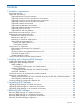
Contents 1 Installation requirements..............................................................................5 System requirements..................................................................................................................5 Supported environments............................................................................................................6 Supported Business Copy environments...................................................................................
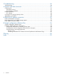
5 Troubleshooting........................................................................................46 Troubleshooting......................................................................................................................46 6 Support and other resources......................................................................47 Contacting HP........................................................................................................................47 Subscription service.........
1 Installation requirements This chapter describes Installation requirements. System requirements RAID Manager operations involve the RAID Manager software on the UNIX/PC server host, the command device(s) on the RAID storage system(s), and the logical volumes on the RAID storage system(s). The system requirements for RAID Manager are: • RAID Manager software product. The RAID Manager software is supplied on CD-ROM or diskette. The RAID Manager software files take up 2.5 MB of space.
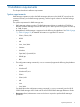
• Host memory: ◦ Static memory capacity: minimum = 300 KB, maximum = 500 KB ◦ Dynamic memory capacity (set in HORCM_CONF): maximum = 500 KB per unit ID • Failover: RAID Manager supports several failover products, including FirstWatch, MC/ServiceGuard, HACMP, TruCluster, and ptx/CLUSTERS. See Table 2 (page 7) – Table 10 (page 12) for detailed information.
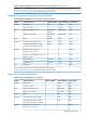
Table 1 Supported platforms for Business Copy (continued) Vendor Operating System Failover Software Volume Manager I/O Interface 1 IBM Microsoft HP-UX 11.2x on IA64 MC/Service Guard LVM, SLVM Fibre Digital UNIX 4.0 TruCluster LSM SCSI Tru64 UNIX 5.0 TruCluster LSM SCSI/Fibre OpenVMS 7.3-1 – – Fibre DYNIX/ptx 4.4 ptx/Cluster LVM SCSI/Fibre AIX 4.3 HACMP LVM SCSI/Fibre z/Linux (Suse 8) For restrictions on z/Linux, – see “Requirements and restrictions for z/Linux” (page 13).
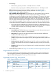
Table 2 Supported platforms for Continuous Access Synchronous (continued) Vendor Operating System Failover Software Volume Manager I/O Interface Microsoft Windows NT 4.0; Windows 2000, 2003, 2008 MSCS LDM Fibre Windows 2003/2008 on IA641 MSCS LDM Fibre – – SCSI/Fibre** AS/ES 2.1, 3.0 Update2, 4.0, 5.0 on EM64T / IA641 – – Fibre IRIX64 6.5 – – SCSI/Fibre Windows 2003/2008 on EM64T Red Hat Red Hat Linux 6.0, 7.0, 8.0 AS/ES 2.1, 3.0, 4.0, 5.
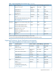
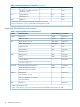
Table 3 Supported platforms for Continuous Access Asynchronous (continued) Vendor 2 Operating System Failover Software Volume Manager I/O Interface See “Troubleshooting” (page 46) about RHEL 4.0 using Kernel 2.6.9.XX. Supported Continuous Access Journal environments Table 4 Supported Platforms for Continuous Access Journal Vendor Operating System Failover Software Volume Manager I/O Interface Oracle Solaris 2.8 VCS VxVM Fibre Solaris 10 /x86 – VxVM Fibre HP-UX 10.20/11.0/11.
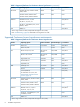
Table 5 Supported platforms for Snapshot (continued) Vendor HP SGI Operating System Failover Software Volume Manager I/O Interface AS/ES 2.1, 3.0 Update 2, 4.0, 5.0 on EM64T / IA64* – – Fibre** Tru64 UNIX 5.0 – LSM Fibre OpenVMS 7.3-1 – – Fibre IRIX64 6.5 – – Fibre 1 IA64: using IA-32EL on IA64 (except RAID Manager for Linux/IA64) 2 See “Troubleshooting” (page 46) about RHEL 4.0 using Kernel 2.6.9.XX.
Supported Database Validator environments Table 7 Supported platforms for Database Validator Vendor Operating system Volume Manager I/O interface Oracle Solaris 2.5 VxVM SCSI/Fibre Solaris 10 /x86 VxVM Fibre HP-UX 10.20/11.0/11.2x LVM, SLVM SCSI/Fibre HP-UX 11.2x on IA641 LVM, SLVM Fibre Digital UNIX 4.0 LSM SCSI Tru64 UNIX 5.0 LSM SCSI/Fibre OpenVMS 7.3-1 – Fibre DYNIX/ptx 4.4 LVM SCSI/Fibre AIX 4.3 LVM SCSI/Fibre z/Linux (SUSE 8) – Fibre (FCP) Windows NT4.
Table 8 (continued) VM Vendor Windows 2008 Hyper-V *3 Layer Guest OS RAID Manager support confirmation Volume mapping I/O interface Server AIX 5.3 See (4) in “Restrictions on AIX VIO” (page 15) Direct Fibre Child Windows 2003 SP2 Confirmed Path-thru Fibre Windows 2008 Path-thru Fibre Windows 2000 SP4 Unconfirmed - - SLES10 SP2 Confirmed Path-thru Fibre Windows 2008 Confirmed Direct Fibre Parent Confirmed * RDM: Raw Device Mapping using Physical Compatibility Mode.
Table 10 Supported platforms: IPv4 vs. IPv6 (continued) RAID Manager / IPv6 *1 IPv6 IPv4 Tru64 AV AV AV N/A AV AV N/A OpenVMS AV AV AV N/A AV AV AV IRIX64 AV AV AV N/A AV AV N/A DYNIX N/A N/A N/A N/A N/A N/A N/A 1: See “About platforms supporting IPv6” (page 18). Legend AV: Available for communicating with different platforms. N/A: Not Applicable (Windows LH does not support IPv4 mapped IPv6). Minimum platform versions for RAID Manager/IPv6 support: • HP-UX: HP-UX 11.
The restrictions for using RAID Manager with z/Linux are: • Command device. RAID Manager uses a SCSI Path-through driver to access the command device. As such, the command device must be connected through FCP adaptors. • Open Volumes via FCP. You can control the Business Copy and Continuous Access Synchronous pair operations without any restrictions. • Mainframe (3390-9A) Volumes via FICON. You cannot control the volumes (3390-9A) that are directly connected to FICON for Business Copy pair operations.
Figure 2 RAID Manager configuration on guest OS/VMware The restrictions for using RAID Manager with VMware are: 1. Guest OS. RAID Manager needs to use guest OS that is supported by RAID Manager, and also VMware supported guest OS (for example, Windows Server 2003, Red Hat Linux, SUSE Linux). See “Supported guest OS for VM” (page 11). 2. Command device. RAID Manager uses SCSI path-through driver to access the command device.
Figure 3 RAID Manager configuration on VIO client The restrictions for using RAID Manager on AIX VIO are as follows: 1. Command device. RAID Manager uses the SCSI Path-through driver for accessing the command device. Therefore, the command device must be mapped as RAW device of Physical Mapping Mode. At least one command device must be assigned for each VIO Client.
4. About running on VIO Server. The volume mapping ( /dev/rhdisk) on a VIO Server is a physical connection without converting SCSI Inquiry, so RAID Manager will perform as if running on AIX 5.3. However, IBM does not allow running applications in the VIO server. Since commands or scripts would have to be run outside the restricted shell, it may be necessary to get IBM approval to run in the VIO server.
About platforms supporting IPv6 Library and system call for IPv6 RAID Manager uses the following functions of IPv6 library to get and convert from hostname to IPv6 address.
horcmstart.sh 10 • $IPV6_GET_ADDR: This variable is used to change “AI_PASSIVE” value as default for specifying to the getaddrinfo() function for IPv6. For example: export IPV6_GET_ADDR=9 horcmstart.sh 10 HORCM startup log Support level of IPv6 feature depends on the platform and OS version. In certain OS platform environments, RAID Manager cannot perform IPv6 communication completely, so RAID Manager logs the results of whether the OS environment supports the IPv6 feature or not.
(4) Startup method for HORCM daemon HORCM can start as the daemon process from a UNIX Shell. But in the case of ‘vfork’ of CRTL, if a parent process has exit() then a child process also ends at the same time. In other words it looks that OpenVMS cannot make a daemon process from the POSIX program. Therefore, horcmstart.exe has been changed to wait until HORCM has been exiting by horcmshutdown.exe after startup of the horcmgr. According to the rule for creating process in OpenVMS, to start up the horcmstart.
“DG*,DK*,GK*” as the logical name for the device. The SCSI class driver requires the following privileges: DIAGNOSE and PHY_IO or LOG_IO (for details see the OpenVMS manual). In RAID Manager version 01-12-03/03 or earlier, you need to define the Physical device as either DG* or DK* or GK* by using DEFINE/SYSTEM command.
For example, using spawn: $ spawn /NOWAIT /PROCESS=horcm0 horcmstart 0 %DCL-S-SPAWNED, process HORCM0 spawned $ starting HORCM inst 0 $ spawn /NOWAIT /PROCESS=horcm1 horcmstart 1 %DCL-S-SPAWNED, process HORCM1 spawned $ starting HORCM inst 1 $ The subprocess (HORCM) created by SPAWN is terminated when the terminal is LOGOFF or the session is terminated. If you want independence Process to the terminal LOGOFF, then use the “RUN /DETACHED” command.
$ PRODUCT SHOW HISTORY RM /FULL For removing : $ PRODUCT REMOVE RM /LOG (13) About exit code of the command on DCL RAID Manager return codes are the same for all platforms. However, if the process was invoked by the DCL, the status is interpreted by DCL and a message appears as below.
Startup procedures using detached process on DCL (1) Create the shareable Logical name for RAID if undefined initially. RAID Manager needs to define the physical device ($1$DGA145…) as either DG* or DK* or GK* by using SHOW DEVICE command and DEFINE/SYSTEM command, but then does not need to be mounted in RAID Manager version 01-12-03/03 or earlier.
VG01 VG01 VG01 HORCM_INST #dev_group VG01 oradb1 oradb2 oradb3 CL1-H CL1-H CL1-H ip_address HOSTB 0 0 0 2 4 6 0 0 0 service horcm1 For horcm1.conf HORCM_DEV #dev_group VG01 VG01 VG01 HORCM_INST #dev_group VG01 dev_name oradb1 oradb2 oradb3 port# CL1-H CL1-H CL1-H ip_address HOSTA TargetID 0 3 0 5 0 7 LU# MU# 0 0 0 service horcm0 Defines the UDP port name for HORCM communication in the SYS$SYSROOT:[000000.TCPIP$ETC]SERVICES.DAT file, as in the example below.
(2) Removing the environment variable. $ DELETE/SYMBOL HORCC_MRCF $ pairdisplay -g VG01 -fdc Group PairVol(L/R) Device_File VG01 oradb1(L) DKA146 VG01 oradb1(R) DKA147 VG01 oradb2(L) DKA148 VG01 oradb2(R) DKA149 VG01 oradb3(L) DKA150 VG01 oradb3(R) DKA151 $ ,Seq#,LDEV#.P/S,Status,Fence, % ,P-LDEV# 30009 146..SMPL ---- ------,----- ---30009 147..SMPL ---- ------,----- ---30009 148..SMPL ---- ------,----- ---30009 149..SMPL ---- ------,----- ---30009 150..SMPL ---- ------,----- ---30009 151..
# ERROR [CMDDEV] DKA145 HORCM_DEV #dev_group dev_name # DKA146 SER = URA URA_000 # DKA147 SER = URA URA_001 # DKA148 SER = URA URA_002 # DKA149 SER = URA URA_003 # DKA150 SER = URA URA_004 HORCM_INST #dev_group ip_address URA 127.0.0.
(1) Create the shareable Logical name for RAID if undefined initially. You need to define the Physical device ($1$DGA145…) as either DG* or DK* or GK* by using the SHOW DEVICE command and the DEFINE/SYSTEM command, but then it does not need to be mounted.
HORCM_DEV #dev_group VG01 VG01 VG01 HORCM_INST #dev_group VG01 dev_name oradb1 oradb2 oradb3 port# CL1-H CL1-H CL1-H ip_address HOSTB TargetID 0 2 0 4 0 6 LU# MU# LU# MU# 0 0 0 service horcm1 FOR horcm1.conf HORCM_DEV #dev_group VG01 VG01 VG01 HORCM_INST #dev_group VG01 dev_name oradb1 oradb2 oradb3 port# CL1-H CL1-H CL1-H ip_address HOSTA TargetID 0 3 0 5 0 7 0 0 0 service horcm0 (7) Start ‘horcmstart 0 1’. The subprocess (HORCM) created by bash is terminated when the bash is EXIT.
Table 11 Relationship between CCI and RAID storage system (continued) CCI version Installation order RAID system Common API/CLI XP API/CLI pairvolchk pairevtwait pairdisplay raidscan (except -find option only), raidar raidvchkset raidvchkdsp raidvchkscan 2.
2 Installing and configuring RAID Manager This chapter describes installing and configuring RAID Manager. Installing the RAID Manager hardware Installation of the hardware required for RAID Manager is performed by the user and the HP representative. To install the hardware required for RAID Manager operations: 1. User: 1. Make sure that the UNIX/PC server hardware and software are properly installed and configured. See “Supported environments” (page 6). 2.
be different on your platform. Please consult your operating system documentation (for example, UNIX man pages) for platform-specific command information. To install the RAID Manager software in the root directory: 1. Insert the installation medium into the I/O device properly. 2. Move to the current root directory: # cd /. 3. Copy all files from the installation medium using the cpio command: 4.
1. 2. 3. 4. 5. Change the owner of the following RAID Manager files from the root user to the desired user name: • /HORCM/etc/horcmgr • All RAID Manager commands in the /HORCM/usr/bin directory • All RAID Manager log directories in the /HORCM/log* directories Change the owner of the raw device file of the HORCM_CMD command device in the configuration definition file from the root user to the desired user name.
Windows installation Make sure to install RAID Manager on all servers involved in RAID Manager operations. If network (TCP/IP) is not established, install a network of Windows attachment, and add TCP/IP protocol. To install the RAID Manager software on a Windows system: 1. If a previous version of RAID Manager is installed, remove it according to the instructions in “Removing RAID Manager in a Windows environment” (page 44). 2. Insert the installation medium (for example, CD-ROM) into the proper I/O device.
Because the ACL (Access Control List) of the Device Objects is set every time Windows starts-up, the Device Objects are also required when Windows starts-up. The ACL is also required when new Device Objects are created. RAID Manager administrator tasks 1. 2. Establish the HORCM (/etc/horcmgr) startup environment.
2. Execute the following command: $ PRODUCT INSTALL RM /source=Device:[PROGRAM.RM.OVMS]/LOG _$ /destination=SYS$POSIX_ROOT:[000000] Device:[PROGRAM.RM.OVMS] where HITACH-ARMVMS-RM-V0122-2-1.PCSI exists 3. Verify installation of the proper version using the raidqry command: $ raidqry -h Model: RAID-Manager/OpenVMS Ver&Rev: 01-22-03/06 Usage: raidqry [options] 4. Follow the requirements and restrictions in “Porting notice for OpenVMS” (page 19).
Figure 7 System configuration example and setting example of command device and virtual command device by in-band and out-of-band methods Setting the command device RAID Manager commands are issued to the RAID storage system via the command device. The command device is a user-selected, dedicated logical volume on the storage system that functions as the interface to the RAID Manager software on the UNIX/PC host.
3. 4. 5. 6. Configure the device as needed before setting it as a command device. For example, use Virtual LUN or Virtual LVI to create a device that has 36 MB of storage capacity. For instructions, see the HP XP P9000 Provisioning for Open Systems User Guide. Launch LUN Manager, locate and select the device, and set the device as a command device. For more information, see the HP XP P9000 Provisioning for Open Systems User Guide.
Example 3 Setting example of virtual command device in configuration definition file (out-of-band method) HORCM_CMD #dev_name \\.\IPCMD-192.168.1.100-31001 dev_name dev_name About alternate command devices If RAID Manager receives an error notification in reply to a read or write request to a command device, the RAID Manager software can switch to an alternate command device, if one is defined.
Creating/editing the configuration definition file The configuration definition file is a text file that is created and edited using any standard text editor (for example, UNIX vi editor, Windows Notepad). The configuration definition file defines correspondences between the server and the volumes used by the server. There is a configuration definition file for each host server. When the RAID Manager software starts up, it refers to the definitions in the configuration definition file.
Table 12 Configuration (HORCM_CONF) parameters (continued) Parameter Default Type Limit MU# 0 Numeric value 7 characters See *1 Serial# None Numeric value 12 characters CU:LDEV(LDEV#) None Numeric value 6 characters dev_name for HORCM_CMD None Character string 63 characters Recommended value = 8 char. or less 1: Use decimal notation for numeric values (not hexadecimal). Do not edit the configuration definition file while RAID Manager is running.
3 Upgrading RAID Manager For upgrading RAID Manager software, the RMuninst script on the CD-ROM is used. For other media, use the following instructions to upgrade the RAID Manager software. The instructions may be different for your platform. Consult your operating system documentation (for example, UNIX man pages) for platform-specific command information. Upgrading RAID Manager in a UNIX environment Use the RMinstsh script on the CD-ROM to upgrade the RAID Manager software to a later version.
6. 7. 8. 9. The Run window opens, enter A:\Setup.exe (where A: is diskette or CD drive) in the Open pull-down list box. An InstallShield will open. Follow the on screen instructions to install the RAID Manager software. Reboot the Windows server, and verify that the correct version of the RAID Manager software is running on your system by executing the raidqry -h command.
4 Removing RAID Manager This chapter explains how to remove RAID Manager. Removing RAID Manager in a UNIX environment To remove the RAID Manager software: 1. If you are discontinuing local and/or remote copy functions (for example, Business Copy, Continuous Access Synchronous), delete all volume pairs and wait until the volumes are in simplex status. If you will continue copy operations using Remote Web Console, do not delete any volume pairs. 2.
2. You can remove the RAID Manager software only when RAID Manager is not running. If RAID Manager software is running, shut down RAID Manager using the horcmshutdown command to ensure a normal end to all functions: One RAID Manager instance: D:\HORCM\etc> horcmshutdown Two RAID Manager instances: D:\HORCM\etc> horcmshutdown 0 1 3. Delete the RAID Manager software using the Add or Remove Programs control panel: 1. Open the Control Panel, and double-click Add or Remove Programs. 2.
5 Troubleshooting This chapter provides troubleshooting information. Troubleshooting If you have a problem installing or upgrading the RAID Manager software, ensure that all system requirements and restrictions have been met.
6 Support and other resources Contacting HP For worldwide technical support information, see the HP support website: http://www.hp.
HP websites For additional information, see the following HP websites: • http://www.hp.com • http://www.hp.com/go/storage • http://www.hp.com/service_locator • http://www.hp.com/support/manuals • http://www.hp.com/support/downloads • http://www.hp.
Table 13 Document conventions (continued) Convention Element Monospace text • File and directory names • System output • Code • Commands, their arguments, and argument values Monospace, italic text • Code variables • Command variables Monospace, bold text WARNING! CAUTION: IMPORTANT: NOTE: TIP: Emphasized monospace text Indicates that failure to follow directions could result in bodily harm or death. Indicates that failure to follow directions could result in damage to equipment or data.
A Fibre-to-SCSI address conversion Disks connected with Fibre Channel display as SCSI disks on UNIX hosts. Disks connected with Fibre Channel connections can be fully utilized. RAID Manager converts Fibre Channel physical addresses to SCSI target IDs (TIDs) using a conversion table (see Figure 9 (page 50)). Table 14 (page 50) shows the current limits for SCSI TIDs and LUNs on various operating systems.
Example 6 Using Raidscan to display TID and LUN for Fibre Channel devices C:\>raidscan -pd hd6 -x drivescan hd6 Harddisk 6... Port[ 2] PhId[ 4] TId[ 3] Lun[ 5] [HITACHI ] [OPEN-3 Port[CL1-J] Ser#[ 30053] LDEV#[ 14(0x00E)] HORC = SMPL HOMRCF[MU#0 = SMPL MU#1 = SMPL MU#2 = SMPL] RAID5[Group 1- 2] SSID = 0x0004 PORT# /ALPA/C,TID#,LU#.Num(LDEV#....)...P/S, Status,Fence,LDEV#,P-Seq#,P-LDEV# CL1-J / e2/4, 29, 0.1(9).............SMPL ---- ------ ----, ----- ---CL1-J / e2/4, 29, 1.1(10)............
Figure 10 LUN configuration RAID Manager uses absolute LUNs to scan a port, whereas the LUNs on a group are mapped for the host system so that the target ID & LUN, that is indicated by the raidscan command, is different from the target ID & LUN shown by the host system. In this case, the target ID & LUN indicated by the raidscan command should be used. In this case, you must start HORCM without a description for HORCM_DEV and HORCM_INST because target ID & LUN are unknown.
The conversion table for Windows systems is based on the Emulex driver. If a different Fibre Channel adapter is used, the target ID indicated by the raidscan command may be different than the target ID indicated by the Windows system. Note on Table 3 for other Platforms: Table 3 is used to indicate the LUN without Target ID for unknown FC_AL conversion table or Fibre Channel fabric (Fibre Channel WWN). In this case, the Target ID is always zero, thus Table 3 is not described in this document.
Table 16 Fibre address conversion table for Solaris and IRIX systems (Table1) (continued) C0 C1 C2 C3 C4 C5 C6 C7 AL-PA TID AL-PA TID AL-PA TID AL-PA TID AL-PA TID AL-PA TID AL-PA TID AL-PA TID D9 8 C3 24 A7 40 80 56 67 72 4B 88 2E 104 10 120 D6 9 BC 25 A6 41 7C 57 66 73 4A 89 2D 105 0F 121 D5 10 BA 26 A5 42 7A 58 65 74 49 90 2C 106 08 122 D4 11 B9 27 A3 43 79 59 63 75 47 91 2B 107 04 123 D3 12 B6 28 9F 44 76 60 5C 76
B Sample configuration definition files This chapter describes sample configuration definition files. Sample configuration definition files Figure 11 (page 55) illustrates the configuration definition of paired volumes. Example 9 “Configuration file example – UNIX-based servers” shows a sample configuration file for a UNIX-based operating system. Figure 12 (page 56) shows a sample configuration file for a Windows operating system.
Example 9 Configuration file example – UNIX-based servers HORCM_MON #ip_address service poll(10ms) timeout(10ms) HST1 horcm 1000 3000 HORCM_CMD #unitID 0... (seq#30014) #dev_name dev_name dev_name /dev/rdsk/c0t0d0 #unitID 1...
• Poll: The interval for monitoring paired volumes. To reduce the HORCM daemon load, make this interval longer. If set to -1, the paired volumes are not monitored. The value of -1 is specified when two or more RAID Manager instances run on a single machine. • Timeout: The time-out period of communication with the remote server. (2) HORCM_CMD The command parameter (HORCM_CMD) defines the UNIX device path or Windows physical device number of the command device.
If Windows has two different array models that share the same serial number, fully define the serial number, ldev#, port and host group for the CMDDEV. • For under Multi Path Driver. Specifies to use any port as the command device for Serial#30095, LDEV#250 \\.\CMD-30095-250 • For full specification. Specifies the command device for Serial#30095, LDEV#250 connected to Port CL1-A, Host group#1 \\.\CMD-30095-250-CL1-A-1 • Other examples \\.\CMD-30095-250-CL1-A \\.
\\.\IPCMD-158.214.135.113-31001 (3) HORCM_DEV The device parameter (HORCM_DEV) defines the RAID storage system device addresses for the paired logical volume names. When the server is connected to two or more storage systems, the unit ID is expressed by port# extension. Each group name is a unique name discriminated by a server which uses the volumes, the attributes of the volumes (such as database data, redo log file, UNIX file), recovery level, etc.
- Basic CLC an bn cn dn en fn gn hn jn kn ln mn nn pn qn rn CLD an bn cn dn en fn gn hn jn kn ln mn nn pn qn rn CLE an bn cn dn en fn gn hn jn kn ln mn nn pn qn rn CLF an bn cn dn en fn gn hn jn kn ln mn nn pn qn rn CLG an bn cn dn en fn gn hn jn kn ln mn nn pn qn rn • Option Option Option Target ID: Defines the SCSI/Fibre target ID number of the physical volume on the specified port.
The following values are defined in the HORCM_INST parameter: • dev_group: The server name described in dev_group of HORC_DEV. • ip_address: The network address of the specified remote server. • service: The port name assigned to the HORCM communication path (registered in the /etc/services file). If a port number is specified instead of a port name, the port number is used. When HORCM has two or more network addresses on different subnets for communication, the ip_address of HORCM_MON must be NONE.
Figure 15 Network configuration for IPv6 It is possible to communicate between HORCM/IPv4 and HORCM/IPv6 using IPv4 mapped to IPv6. Figure 16 Network configuration for IPv4 mapped to IPv6 In the case of mixed IPv4 and IPv6, it is possible to communicate between HORCM/IPv4 and HORCM/IPv6 and HORCM/IPv6 using IPv4 mapped to IPv6 and native IPv6.
Figure 17 Network configuration for mixed IPv4 and IPv6 (5) HORCM_LDEV The HORCM_LDEV parameter is used for specifying stable LDEV# and Serial# as the physical volumes corresponding to the paired logical volume names. Each group name is unique and typically has a name fitting its use (for example, database data, Redo log file, UNIX file). The group and paired logical volume names described in this item must also be known to the remote server. 1. dev_group: This parameter is the same as HORCM_DEV parameter.
oradb oradb • dev1 dev2 30095 30095 02:40 02:41 0 0 Specifying “CU:LDEV” in hex used by SVP or Remote Web Console. Example for LDEV# 260 01: 04 • Specifying “LDEV” in decimal used by the RAID Manager inqraid command. Example for LDEV# 260 260 • Specifying “LDEV” in hex used by the RAID Manager inqraid command. Example for LDEV# 260 0x104 HORCM_LDEV format can be used for XP1024/XP128 Disk Array and later.
The command device is defined using the system raw device name (character-type device file name). For example, the command devices for the following figure would be: • HP-UX: HORCM_CMD of HOSTA = /dev/rdsk/c0t0d1 HORCM_CMD of HOSTB = /dev/rdsk/c1t0d1 • Solaris: HORCM_CMD of HOSTA = /dev/rdsk/c0t0d1s2 HORCM_CMD of HOSTB = /dev/rdsk/c1t0d1s2 For Solaris operations with RAID Manager version 01-09-03/04 and higher, the command device does not need to be labeled during format command.
Example of RAID Manager commands with HOSTA: • Designate a group name (Oradb) and a local host P-VOL a case. # paircreate -g Oradb -f never -vl This command creates pairs for all LUs assigned to group Oradb in the configuration definition file (two pairs for the configuration in the above figure). • Designate a volume name (oradev1) and a local host P-VOL a case.
where XX = device number assigned by Tru64 UNIX • DYNIX/ptx: HORCM_CMD of HOSTA = /dev/rdsk/sdXX HORCM_CMD of HOSTB = /dev/rdsk/sdXX where XX = device number assigned by DYNIX/ptx • Windows 2008/2003/2000: HORCM_CMD of HOSTA = \\.\CMD-Ser#-ldev#-Port# HORCM_CMD of HOSTB = \\.\CMD-Ser#-ldev#-Port# • Windows NT: HORCM_CMD of HOSTA = \\.\CMD-Ser#-ldev#-Port# HORCM_CMD of HOSTB = \\.
Example of RAID Manager commands with HOSTA: • Designate a group name (Oradb) and a local host P- VOL a case. # paircreate -g Oradb -f never -vl This command creates pairs for all LUs assigned to group Oradb in the configuration definition file (two pairs for the configuration in above figure). • Designate a volume name (oradev1) and a local host P-VOL a case.
For Solaris operations with RAID Manager version 01-09-03/04 and higher, the command device does not need to be labeled during format command.
Figure 20 Continuous Access Synchronous configuration example for two instances Example of RAID Manager commands with Instance-0 on HOSTA: • When the command execution environment is not set, set an instance number.
For Windows: set HORCMINST=0 • Designate a group name (Oradb) and a local instance P- VOL a case. # paircreate -g Oradb -f never -vl This command creates pairs for all LUs assigned to group Oradb in the configuration definition file (two pairs for the configuration in above figure). • Designate a volume name (oradev1) and a local instance P-VOL a case.
For Solaris operations with RAID Manager version 01-09-03/04 and higher, the command device does not need to be labeled during format command.
Figure 21 Business Copy configuration example (continues in next figure) Examples of RAID Manager configurations 73
Figure 22 Business Copy configuration example (continued) Example of RAID Manager commands with HOSTA (group Oradb): • When the command execution environment is not set, set HORCC_MRCF to the environment variable.
Windows: set HORCC_MRCF=1 • Designate a group name (Oradb) and a local host P-VOL a case. # paircreate -g Oradb -vl This command creates pairs for all LUs assigned to group Oradb in the configuration definition file (two pairs for the configuration in above figure). • Designate a volume name (oradev1) and a local host P-VOL a case.
For Windows: set HORCC_MRCF=1 • Designate a group name (Oradb1) and a local host P-VOL a case. # paircreate -g Oradb1 -vl This command creates pairs for all LUs assigned to group Oradb1 in the configuration definition file (two pairs for the configuration in the above figure). • Designate a volume name (oradev1-1) and a local host P-VOL a case.
For Windows: set HORCC_MRCF=1 • Designate a group name (Oradb2) and a local host P-VOL a case. # paircreate -g Oradb2 -vl This command creates pairs for all LUs assigned to group Oradb2 in the configuration definition file (two pairs for the configuration in above figure). • Designate a volume name (oradev2-1) and a local host P-VOL a case.
For Solaris operations with RAID Manager version 01-09-03/04 and higher, the command device does not need to be labeled during format command.
Figure 23 Business Copy configuration example with cascade pairs See “Configuration definition for cascading volume pairs” (page 84) for more information on Business Copy cascading configurations. Example of RAID Manager commands with Instance-0 on HOSTA: • When the command execution environment is not set, set an instance number.
For Windows: set HORCMINST=0 set HORCC_MRCF=1 • Designate a group name (Oradb) and a local instance P- VOL a case. # paircreate -g Oradb -vl # paircreate -g Oradb1 -vr # paircreate –g oradb –pvol These commands create pairs for all LUs assigned to groups Oradb and Oradb1 in the configuration definition file. • Designate a group name and display pair status.
For Solaris operations with RAID Manager version 01-09-03/04 and higher, the command device does not need to be labeled during format command. • AIX: HORCM_CMD of HOSTA(/etc/horcm.conf) ... /dev/rhdiskXX HORCM_CMD of HOSTB(/etc/horcm.conf) ... /dev/rhdiskXX HORCM_CMD of HOSTB(/etc/horcm0.conf)... /dev/rhdiskXX where XX = device number assigned by AIX • Tru64 UNIX: HORCM_CMD of HOSTA(/etc/horcm.conf) ... /dev/rrzbXXc HORCM_CMD of HOSTB(/etc/horcm.conf) ... /dev/rrzbXXc HORCM_CMD of HOSTB(/etc/horcm0.
Figure 24 Continuous Access Synchronous/Business Copy configuration example with cascade pairs Example of RAID Manager commands with HOSTA and HOSTB: • Designate a group name (Oradb) on Continuous Access Synchronous environment of HOSTA. # paircreate -g Oradb • -vl Designate a group name (Oradb1) on Business Copy environment of HOSTB. When the command execution environment is not set, set HORCC_MRCF.
These commands create pairs for all LUs assigned to groups Oradb and Oradb1 in the configuration definition file (four pairs for the configuration in the above figures). • Designate a group name and display pair status on HOSTA. # pairdisplay -g oradb -m cas Group PairVol(L/R) (Port#,TID,LU-M),Seq#,LDEV#.P/S,Status, Seq#,P-LDEV# oradb oradev1(L) (CL1-A , 1, 1-0)30052 266..SMPL ----,-------oradb oradev1(L) (CL1-A , 1, 1) 30052 266..P-VOL COPY,30053 268 oradb1 oradev11(R) (CL1-D , 2, 1-0)30053 268..
oradb2 oradb oradev22(R) (CL1-D , 2, oradev2(R) (CL1-D , 2, 2-1)30053 2) 30053 269..SMPL ----,----269..S-VOL PAIR,----- ---267 - Configuration definition for cascading volume pairs The RAID Manager software (HORCM) is capable of keeping track of up to seven pair associations per LDEV (1 for Cnt Ac-S/Cnt Ac-J, 3 for Cnt Ac-J, 3 for BC/Snapshot, 1 for Snapshot).
Table 18 Mirror descriptors and group assignments (continued) HORCM_DEV parameter in configuration file HORCM_DEV #dev_group LU# MU# dev_name port# TargetID Oradb 1 oradev1 CL1-D 2 Oradb1 1 0 oradev11 CL1-D 2 Oradb2 1 1 oradev21 CL1-D 2 Oradb3 1 2 oradev31 CL1-D 2 HORCM_DEV #dev_group LU# MU# dev_name port# TargetID Oradb 1 0 oradev1 CL1-D 2 HORCM_DEV #dev_group LU# MU# dev_name port# TargetID Oradb 1 0 oradev1 CL1-D 2 Oradb1 1 1 oradev1 CL1-D 2 Oradb2 1 2 oradev21
sections present examples of Business Copy and Business Copy/Continuous Access Synchronous cascading configurations. Business Copy The following figure shows an example of a Business Copy cascade configuration and the associated entries in the configuration definition files. Business Copy is a mirror configuration within one storage system, so the volumes are described in the configuration definition file for each HORCM instance: volumes T3L0, T3L4, and T3L6 in HORCMINST0, and volume T3L2 in HORCMINST1.
Figure 28 Pairdisplay -g on HORCMINST1 Figure 29 Pairdisplay -d on HORCMINST0 Cascading connections for Continuous Access Synchronous and Business Copy The cascading connections for Continuous Access Synchronous/Business Copy can be set up by using three configuration definition files that describe the cascading volume entity in a configuration definition file on the same instance.
Figure 30 Continuous Access Synchronous/Business Copy cascading connection and configuration file The following figures cascading configurations and the pairdisplay information for each configuration.
Figure 32 Pairdisplay for Continuous Access Synchronous on HOST2 (HORCMINST) Figure 33 Pairdisplay for Business Copy on HOST2 (HORCMINST) Figure 34 Pairdisplay for Business Copy on HOST2 (HORCMINST0) Examples of RAID Manager configurations 89
Glossary AL-PA Arbitrated loop physical address. A 1-byte value that the arbitrated loop topology uses to identify the loop ports. This value becomes the last byte of the address identifier for each public port on the loop. BC P9000 or XP Business Copy. An HP application that provides volume-level, point-in-time copies in the disk array. CB Circuit breaker. CLI Command-line interface. An interface comprised of various commands which are used to control operating system responses.
LUSE Logical Unit Size Expansion. The LUSE feature is available when the HP StorageWorks LUN Manager product is installed, and allows a LUN, normally associated with only a single LDEV, to be associated with 1 to 36 LDEVs. Essentially, LUSE makes it possible for applications to access a single large pool of storage. MCU Main control unit. MSCS Microsoft Cluster Service. MU Mirror unit.
Index A access requirements, 5 AIX VIO, restrictions, 15 alternate command devices, 39 C cascading, configuration definitions, 84 changing the user UNIX environment, 32 Windows environment, 34 command devices alternate, 39 requirements, 6 setting, 37 virtual, 38 command execution, 36 components, removing, 45 configuration examples, 64 configuration file cascading examples, 85 cascading volume pairs, 84 creating, 40 editing, 40 examples, 55 mirror descriptors, 84 parameters, 40 sample file, 40 configuration
I license key requirements, 6 LUN configurations, 51 components, 45 OpenVMS environment, 45 UNIX environment, 44 Windows environment, 44 software upgrade OpenVMS environment, 43 UNIX environment, 42 Windows environment, 42 storage capacity values conventions, 48 Subscriber's Choice, HP, 47 SVC, VMWare restrictions, 15 symbols in text, 49 system requirements, 5 M T memory requirements, 6 mirror descriptors, 84 configuration file correspondence, 84 group assignments, 84 tables, Fibre-to-SCSI address con