HP StorageWorks Disk Array XP1024 site preparation guide fifth edition (July 2005) part number: A7906-96013 This guide describes how to prepare a site for the installation of an HP Disk Array XP1024.
© Copyright 2002-2005 Hewlett-Packard Development Company, L.P., all rights reserved Hewlett-Packard Company makes no warranty of any kind with regard to this material, including, but not limited to, the implied warranties of merchantability and fitness for a particular purpose. Hewlett-Packard shall not be liable for errors contained herein or for incidental or consequential damages in connection with the furnishing, performance, or use of this material.
Contents About this guide 5 Related documentation 5 HP storage web site 5 Helpful web sites 5 HP technical support 6 HP sales and authorized resellers 6 Document conventions and symbols 7 Revision history 8 Contents 1 Introduction 9 2 Site prep team and tasks 11 The site prep team 12 Site prep technical tasks 14 Site planning timetable 16 3 Preparing for installation 17 Safety requirements 18 General computer room requirements 19 Physical requirements 22 HP Disk Array XP512 DKU physical requirements
Electrical requirements 36 Line voltage 36 Branch circuit breakers 37 Frequency 37 AC line voltage requirements for the HP Disk Array XP1024 DKC AC line voltage requirements for the HP Disk Array XP1024 DKU Safety and dedicated ground 46 Grounding requirements 46 Receptacles 47 Power line transients 49 Maximum peak inrush and crest factor 50 Sources of electrical interference 51 AC power cabling requirements 53 Three-phase AC cabling for the USA (60 Hz) 54 Connecting the external power supply cords 54 Branc
About this guide This guide describes how to prepare a physical site for the installation of an HP Disk Array XP1024. For information about the operation of the HP Disk Array XP1024, refer to the owner’s guide.
HP technical support In North America, call technical support at 1-800-633-3600, available 24 hours a day, 7 days a week. Outside North America, call technical support at the location nearest you. The HP web site lists telephone numbers for worldwide technical support at: http://www.hp.com/support. From this web site, select your country.
Document conventions and symbols Table 1. Document conventions Convention Element Blue text (Figure 1) Cross-reference links Bold Menu items, button names, key names, tab names, and group box names Italics Text emphasis and document titles Blue underlined sans serif font (www.hp.com) Web site addresses Caution Indicates that failure to follow directions could result in damage to equipment or data. Warning Indicates that failure to follow directions could result in bodily harm or death.
Revision history 8 May 2002 First edition October 2002 Second edition April 2004 Third edition May 2005 Fourth edition July 2005 Fifth edition HP StorageWorks Disk Array XP1024: Site Preparation Guide
1 Introduction The objective of a site prep is to prepare your site for the successful and timely installation of your HP Disk Array XP1024. Proper site preparation and maintenance is vital to the reliability of the disk array. Other site preparation resources may also be available to you. Consult your HP representative.
HP StorageWorks Disk Array XP1024: Site Preparation Guide
2 Site prep team and tasks The HP service organization is committed to making sure you receive the maximum benefits of your HP Disk Array XP1024. Brief descriptions of the HP team and how they can assist you are included in this chapter. You are also an integral part of the site prep team. Your responsibilities are also described here. The table on page 14 provides a site inspection checklist and includes a reference for pertinent information.
The site prep team The site prep planning team is responsible for determining site location and location size, ensuring that construction requirements and local codes are met, and scheduling all events related to site completion to prepare for the successful installation and maintenance of the HP Disk Array XP1024. The site prep team consists of the following personnel: The HP Sales Representative (SR) The sales representative is your primary point of contact.
• Electrical power input including adherence to: local building codes local electrical codes local safety codes • Connectors and receptacles, including hardware or cables network links telephone equipment equipment supplied by companies other than HP • Environmental requirements including: temperature requirements humidity limitations • Floor ventilation areas • Cable access holes • RJ-11 analog telephone lines for Phone Home capabilities Site prep team and tasks 13
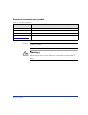
Site prep technical tasks Use the following table as an action item checklist.
Electrical Yes No Reference Are two AC outlets (on different lines) available for the proposed equipment? page 36 Does the input voltage correspond to equipment specifications? page 36 Are the input circuit breakers adequate for equipment loads? page 36 Does the input frequency correspond to equipment specifications? page 36 Are lightning arresters installed? page 51 Have all sources of electrical interferences been corrected? page 51 Yes No
Site planning timetable The following guidelines can be used to monitor the progress of your preinstallation preparation. The time between placing an order to actual arrival can vary, and we recommend conferring with your HP representative to determine the best estimated delivery dates for preparation of your site.
3 Preparing for installation This chapter provides information for planning and preparing your site before and during installation of your HP Disk Array XP1024. Before installing your HP Disk Array XP1024, your site data center computer room must meet the requirements described in this chapter.
Safety requirements The following sections contain information to help you properly prepare your facility for the arrival of your disk array. Site safety consideration When making decisions concerning site safety, your first concern should be the safety of your personnel and then the safety of your equipment. Two major safety considerations for any computer site are fire safety and emergency power-off.
General computer room requirements The goal of a computer room is to maintain an ideal environment for your computer equipment, including your HP Disk Array XP1024. The following guidelines are recommended: • Locate the computer room away from exterior walls of the building to avoid the heat gain from windows and exterior wall surfaces. • When locating near exterior windows is unavoidable, use windows that are double or tripled glazed and shaded to prevent direct sunlight from entering the computer room.
The HP Disk Array XP1024 Your HP Disk Array XP1024 is a high-performance disk array system. It is used to store large quantities of data in an efficient and secure manner. The components of the HP Disk Array XP1024 are contained in one of two types of cabinets. Each HP Disk Array XP1024 has one disk controller cabinet (DKC), which contains the controller electronics for the disk array, and one to five disk-cabinet units (DKUs), which contain the hard disk drives.
When both XP1024 and XP512 DKUs are used, the disk array can have one or two XP1024 DKUs (on one side of the DKC) and one to three XP512 DKUs (on the other side of the DKC) as shown in the figure below. XP1024 and XP512 DKUs cannot be mixed on the same side of the DKC.
Physical requirements Dimensions An HP Disk Array XP1024 consists of a single DKC cabinet and one to four DKU cabinets with the approximate dimensions listed in the table below. Minimum Dimensions DKC mm DKC in DKU mm DKU in Height 1860 73.6 1860 73.6 Width 782* 30.8 750 29.5 Depth 800 31.5 800 31.5 * The width of the DKC includes the side panels. Weight An HP Disk Array XP1024 consists of a single DKC cabinet and one to four DKU cabinets.
Depth Height Weight Fully Loaded DKC Cabinet alone 782 mm 30.8 in 800 mm 31.5 in 1860 mm 73.6 in. 586 kg 1290 lb DKC Cabinet packaged* 1000 mm 39.37 in 2020 mm 79.58 in 674 kg 1484 lb DKU Cabinet alone 750 mm 29.5 in 800 mm 31.5 in 1860 mm 73.6 in 755 kg 1661 lb A7925A DKU 890 mm Cabinet packaged* 35 in 1000 mm 39.37 in 2020 mm 79.58 in 823 kg 1811 lb A7925U DKU 890 mm Cabinet packaged* 35 in 1000 mm 39.37 in 2020 mm 79.
Product Description kg lb A7916B 8-Port 1-2 Gbps Enhanced FC - LW CHIP Pair 4.2 9.2 A7917A Additional CHIP/ACP Power Supply 8.8 19.4 A7918A 2GB Cache Memory Module 0.2 0.4 A7919A Cache Platform Board 5.6 12.3 A7920A Additional Battery for Cache Memory 42.2 92.8 A7921A 512MB Shared Memory Module 0.05 0.1 A7922A Array Control Processor (ACP) pair - High Performance 3.6 7.9 A7924A FC Cable Set for L1 DKU 3.0 6.6 A7926A FC Cable Set for R2 and L2 DKU 3.0 6.
HP Disk Array XP512 DKU physical requirements Dimensions The approximate dimensions of an HP StorageWorks Disk Array XP512 DKU are listed in the table and diagrammed in the figure below. Preparing for installation Minimum Dimensions DKU mm DKU in Height 1790 70.5 Width 600 23.6 Depth 800 31.
Weight The values listed in these tables are approximate and should be used for general reference only. Use these values to estimate the hallway and door clearances as well as floor strength for moving the subsystem frames. The table below lists the physical dimensions for each HP StorageWorks Disk Array XP512 DKU frame component. Component Width Depth Height Weight Fully Loaded A5965A DKU Cabinet alone 600 mm 23.62 in 600 mm 23.62 in 1790 mm 70.53 in.
Service and cable routing space requirements This section contains information about space requirements for the HP Disk Array XP1024. This data should be used as a guideline for space planning development. Space planning HP recommends that you prepare a revised floor plan showing the overall location and arrangement of your computer room, including the addition of your disk array.
The minimum service access is: • Rear: 800 mm (31.5 in) • Side:: 0 mm • Front: 800 mm (31.5 in) Floor loading In addition to the minimum clearance required for servicing, the computer room floor may need additional clearance and requires proper construction to support the total weight of the equipment as well as the localized weight at each caster or foot of the equipment cabinets. A common method of preparing an adequate floor for a computer room is to construct a raised floor over the building floor.
The figure below shows the recommended service clearance and floor cutout recommendations for the XP1024 DKC. Measurements are in millimeters.
The figure below shows the recommended service clearance and floor cutout recommendations for the XP1024 DKU.
The figure below shows the minimum service access and cutouts for the XP1024. a *1 191 b *1 1532 *3 400 225 300 G (Unit: mm) 241 800 G *3 55 113 253 45 110 55 200 680 564 300 555 *3 65 123 250 166 86 16 *2 d G G 450 610 750 420 580 750 FRONT DKC 570 680 800 2400 120 65 181 101 16 800 c *1 DKU Floor cutout area for cables Screw jack Caster Service clearance G Grid panel (over 450mm x 450mm) 1. Clearance (a+b) depends on the floor load rating and clearance (c).
The table below shows the floor load rating for service clearances (minimum configuration). Required clearance (a+b) m Floor load rating (kg/sq. m) Clearance (c) m C=0 C = 0.2 C = 0.4 C = 0.6 C = 1.0 500 0.6 0.4 0.2 0 0 450 0.9 0.7 0.4 0.3 0 400 1.4 1.0 0.8 0.6 0.3 350 2.0 1.6 1.3 1.0 0.7 300 3.0 2.5 2.1 1.8 1.
The figure below shows the maximum service access and cutouts for the XP1024. a *1 b *1 3782 G G G G (Unit: mm) 800 G 800 2400 16 750 750 750 750 750 G G G G G 16 800 Front C *1 DKU DKU DKC DKU DKU Floor cutout area for cables Service clearance G Grid panel (over 450mm x 450mm) Screw jack Caster Clearance (a+b) depends on the floor load rating and clearance (c). The following table lists floor load ratings. Clearance (C) (m) Floor Load Rating (kg/m2) C=0 C = 0.2 C = 0.
Data comm requirements Route data comm cables away from areas of high static electric fields created by power transformers and heavy foot traffic. Use shielded data comm cables that meet approved industrial standards to reduce the effects of external fields. Phone Home with Continuous Track The HP Disk Array XP1024 Phone Home capabilities detect and report problems even before they are noticed by operators and users.
HP StorageWorks XP Remote Web Console and Comand View AE HP StorageWorks Remote Web Console (RWC) is a web-based software application supplied with the XP1024 disk array that permits you to connect to, monitor, and manage the array. For managing multiple XP disk arrays, you can upgrade to the optional Command View XP Advanced Edition (CVXP AE) which also runs in a web browser.
Electrical requirements Power requirements are one of the most important considerations prior to installing your disk array. For disk array cabinets with two connections to AC power, if one input fails, the second input must be capable of supporting the entire current demand nominally shared by the two power connections.
your electrician can determine the current line voltage and make recommendations. Avoid the use of a line voltage conditioner. Make sure that a power distribution unit (if used) supports the correct voltage to support your entire system. Branch circuit breakers See “AC power cabling requirements” on page 53 for the specific branch circuit requirements for your power situation.
The following tables reflect the line voltage for each power cable when the cabinets are cabled with functioning, redundant power cables. AC line voltage requirements for the HP Disk Array XP1024 DKC The table below lists the basic AC power requirements for a 40-amp, single-phase XP1024 DKC.
The table below lists the basic AC power requirements for a 30-amp, single-phase, XP1024 DKC. Nominal Rated Voltage (VAC) Parameter 200 208* 220 230 240 Minimum operating voltage (VAC) 184 191 202 212 221 Maximum operating voltage (VAC) 212 220 233 244 254 Rated line current per power cord (amps RMS) 4.0 3.9 3.6 3.5 3.
The table below lists the basic AC power requirements for a 30-amp, three-phase XP1024 DKC. Nominal Rated Voltage (VAC) Parameter 200 208* 220 230 240 380 400 415 Minimum operating voltage (VAC) 184 191 202 212 221 350 368 382 Maximum operating voltage (VAC) 212 220 233 244 254 403 424 440 Rated line current per power cord (amps RMS) 5.2 5.0 4.7 4.6 4.3 2.7 2.6 2.
AC line voltage requirements for the HP Disk Array XP1024 DKU The table below lists the basic AC power requirements for a 50-amp, single-phase, XP1024 DKU. Nominal Rated Voltage (VAC) Parameter 200 208* 220 230 240 Nominal rated voltage (VAC) 200 208 220 230 240 Minimum operating voltage (VAC) 184 191 202 212 221 Maximum operating voltage (VAC) 212 220 233 244 254 Rated line current per power cord (amps RMS) 22.3 21.6 20.3 19.4 18.
The table below lists the basic AC power requirements for a 30-amp, single-phase XP1024 DKU. Nominal Rated Voltage (VAC) Parameter 200 208* 220 230 240 Minimum operating voltage (VAC) 184 191 202 212 221 Maximum operating voltage (VAC) 212 220 233 244 254 Rated line current per power cord (amps RMS) 13.5 13.0 12.3 11.7 11.
The table below lists the basic AC power requirements for a 60-amp, three-phase XP1024 R1 DKU. Nominal Rated Voltage (VAC) Parameter 200 2081 220 230 240 380 400 415 Minimum operating voltage (VAC) 184 191 202 212 221 350 368 382 Maximum operating voltage (VAC) 212 220 233 244 254 403 424 440 Rated line current per 19.0 18.2 17.2 16.6 15.7 10.7 10.2 power cord (amps RMS) 9.
The table below lists the basic AC power requirements for 60-amp, three-phase, R2, L1, and L2 XP1024 DKUs. Unlike the first DKU (R1), DKUs R2, L1, and L2 do not provide AC power to the DKC. Nominal Rated Voltage (VAC) Parameter 200 2081 220 230 240 380 400 415 Minimum operating voltage (VAC) 184 191 202 212 221 350 368 382 Maximum operating voltage (VAC) 212 220 233 244 254 403 424 440 Rated line current per power cord (amps RMS) 19.0 18.2 17.2 16.6 15.7 10.7 10.2 9.
The table below lists the basic AC power requirements for a 30-amp, three-phase XP1024 DKU. Nominal Rated Voltage (VAC) Parameter 200 208* 220 230 240 380 400 415 Minimum operating voltage (VAC) 184 191 202 212 221 350 368 382 Maximum operating voltage (VAC) 212 220 233 244 254 403 424 440 Rated line current per power cord (amps RMS) 15.0 14.4 13.6 13.0 12.5 8.8 8.4 8.
Safety and dedicated ground The primary reason for grounding electrical systems is safety. The safety ground is required by the National Electric Code (USA) and most other local, regional, and national codes. In addition to safety ground, HP requires that a dedicated (earth reference) ground be installed as a common reference point for all system components. You should consult with your HP CE and your electrician to ensure that your electrical system meets all local and national safety codes.
Receptacles When receptacles are used to connect your disk array components to AC power, they must include a dedicated ground connection that is insulated from the receptacle. It is important that the receptacle box be grounded with an additional ground connection that is separate from the dedicated ground. The additional ground can be hard conduit. Each disk array cabinet has two or four separate connections to AC power (except the 60-amp, three-phase DKC, which has no external power connection).
Specific power plugs and receptacles are required for the XP1024 DKC and DKUs, depending on the power option you specify when ordering the HP Disk Array XP1024. The power cords on 60 Hz cabinets are shipped with plugs attached and connected. The power cords on 50 Hz cabinets are shipped without plugs. Customers are responsible for having the correct plugs and receptacles installed by an electrician in compliance with local electrical requirements and practices.
The Russelstoll connectors are available through most industrial electrical distributors. HP has arranged for these connectors to also be available in stock from the distributors listed below. These distributors are able to ship worldwide and ship via customer preference. Beck Electrical Supply 2775 Goodrick Avenue Richmond, CA 94801 USA Telephone: (800) 466-4395 Fax: (800) 466-5442 Contact: Ken Mogan casales@beckelectric.com Source Research, Inc.
Maximum peak inrush and crest factor The table below shows the maximum peak inrush currents for the HP Disk Array XP1024 DKC and DKUs. Cabinet DKC DKU Power Single-Phase Three-Phase 30-amp 25 A 30 A 40-amp 67 A N/A1 30-amp 33 A 79 A 50-amp 53 A N/A2 60-amp N/A3 99 A4 40 A5 1. The 40-amp power configuration is single-phase only. 2. The 50-amp power configuration is single-phase only. 3. The 60-amp power configuration is three-phase only. 4. First DKU (R1) only.
Sources of electrical interference Ensure that the disk array is protected from sources of electrical interference: wall outlets Convenience power outlets for building maintenance equipment (vacuum cleaners, floor buffers, etc.) must be wired from circuit breakers on a power panel separate from the computer system panel. The ground wires from these outlets must be connected to the normal building distribution panel and not to the system ground.
electromagnetic interference The disk array is specifically designed to reduce its susceptibility to radiated and conducted interference. Electromagnetic interference can cause a variety of system problems. Your HP CE can advise you about many of the most common causes of electromagnetic interference.
AC power cabling requirements Four types of AC power cabling, depending on your location, are specified under the following headings: • “Three-phase AC cabling for the USA (60 Hz)” on page 54 • “Three-phase AC cabling for Europe (50 Hz)” on page 58 • “Single-phase AC cabling for USA” on page 61 • “Single-phase cabling for Europe” on page 65 See the power cabling section that applies to your location and available power.
Three-phase AC cabling for the USA (60 Hz) Each three-phase HP Disk Array XP1024 DKU has two main disconnect devices (two main breakers for dual power lines) so that AC power to the unit can be supplied from separate power distribution panels with two power-supply cords. Warning Trained service personnel should be present whenever the disk array is being connected to a new power source for the first time. Incorrect power connections can cause equipment damage and possible injury or death to personnel.
60-amp, three-phase power When the disk array uses 60-amp, three-phase input power, HP Disk Array XP1024 DKUs have two power cords, but the DKC has no external power cords as shown in the figure below. DKU DKC Breaker lBox #1 Breaker lBox #2 AC Power Input Box #1 AC Power Input Box #2 60 A 60 A In this configuration, an internal cable from the first (R1) DKU provides power to the DKC. If one power source malfunctions, the other power source assumes the total load, providing uninterrupted operation.
30-amp, three-phase power When the disk array uses 30-amp, three-phase input power, HP Disk Array XP1024 DKCs and DKUs have two power cords each as shown in the figure below. DKU DKC AC Power Input Box #1 AC Power Input Box #2 AC Power Input Box #1 AC Power Input Box #2 30 A 30 A 30 A 30 A If one power source malfunctions, the other power source assumes the total load, providing uninterrupted operation.
Branch circuit requirements To protect your disk array, your building must be wired correctly. Each supply (“hot”) conductor must be protected by a short-circuit protective device and by an overcurrent protective device.
Three-phase AC cabling for Europe (50 Hz) Each three-phase HP Disk Array XP1024 DKU has two main disconnect devices (two main breakers for dual power lines) so that AC power to the unit can be supplied from separate power distribution panels with two power-supply cords. Warning Trained service personnel should be present whenever the disk array is being connected to a new power source for the first time. Incorrect power connections can cause equipment damage and possible injury or death to personnel.
disk array and possible injury or death to personnel. To reduce the risk of a wrong connection, you should use a plug and socket that is approved for this disk array. It is your electrician’s responsibility to select and install the proper plug.
Branch circuit requirements When the supplied line to line voltage is in the 380 to 415-volt range, the connection must be a five-wire WYE or STAR connection. To protect your disk array, your building must be wired correctly. Each supply (“hot”) conductor should be protected by a short-circuit protective device and by an overcurrent protective device.
Single-phase AC cabling for USA When configured for 40/50-amp, single-phase power, each HP Disk Array XP1024 cabinet (both the 50-amp DKC and the 40-amp DKUs) has two power cords and two main disconnect devices so that AC power can be supplied from separate power distribution panels. When configured for 30-amp, single-phase power, each HP Disk Array XP1024 cabinet has four power cords and four main disconnect devices.
40/50-amp, single-phase power Each 40/50-amp HP Disk Array XP1024 cabinet has two power-supply cords with attachment plug type Russellstoll 9P53U2 as shown below. DKU DKC AC Power Input Box #1 AC Power Input Box #2 AC Power Input Box #1 AC Power Input Box #2 40 A 40 A 50 A 50 A Be sure to install Russellstoll 9C53U2 or Russellstoll 9R53U2W socket receptacles between the power distribution panel of the building and the attachment plugs for the unit.
30-amp, single-phase power Each 30-amp HP Disk Array XP1024 cabinet has four power-supply cords with attachment plug type Russellstoll 3750DP as shown below. DKU DKC AC Power Input Box #1 AC Power Input Box #2 AC Power Input Box #1 AC Power Input Box #2 30 A 30 A 30 A 30 A 30 A 30 A 30 A 30 A Be sure to install Russellstoll 3933 (alternate, 9C33U0) or 3753 (alternate, 39R33U0W) socket receptacles between the power distribution panel of the building and the attachment plugs for each unit.
Branch circuit requirements To protect your disk array, your building must be wired correctly. Each supply (“hot”) conductor must be protected by a short-circuit protective device and by an overcurrent protective device.
Single-phase cabling for Europe When configured for 40/50-amp, single-phase power, each HP Disk Array XP1024 cabinet (both the 40-amp DKC and the 50-amp DKUs) has two power cords and two main disconnect devices so that AC power can be supplied from separate power distribution panels. When configured for 30-amp, single-phase power, each HP Disk Array XP1024 cabinet has four power cords and four main disconnect devices.
XP1024 Power Cord Black Blue Green/Yellow L1 Line N Neutral G Safety Ground To Power Distribution Panel 30-amp power cords Each 30-amp HP Disk Array XP1024 cabinet has four power-supply cords. The power cords included with the unit are type H07RN-F or equivalent with three 6 mm2 conductors. High leakage current may occur between the power supply and the unit. To avoid an electrical shock, be sure the protective earth connection is made before the supply connections.
Uninterruptible Power Supply (UPS) Caution This uninterruptible power system (UPS) reference is for a product UPS situation. If you are planning or already have a site wide UPS, Hewlett-Packard recommends against a product-specific UPS powered by a site-wide UPS for the XP1024. Most HP Disk Array XP1024 units are installed in data centers where a UPS strategy is already in place. However, if you are making your first large disk array purchase, you may need a separate UPS solution.
Power requirements: single secondary input (primary offline) The values in the table below are based on a worst-case voltage (rated voltage –10%) and a maximum configuration for disk control and disk array frames. A phase imbalance of 15% is also included in the calculation. Input (VAC) 208 Single-Phase Three-Phase DKC Each DKU First DKU Each Additional DKU 13.1 A 36.8 A 31 A 24.6 A N/A N/A 17.4 A 14.
Environmental requirements The environmental specifications for operating your disk array must be satisfied prior to installation. If you intend to use HP Disk Array XP512 DKUs with your HP XP1024 Disk Array, see the HP StorageWorks Disk Array XP512 Site Preparation Guide for environmental requirements for these DKUs. Air conditioning ducts Use separate computer room air conditioning duct work.
Follow these precautions to minimize possible ESD-induced failures in your computer room: • Install conductive flooring (conductive adhesive must be used when laying tiles). • Use conductive wax if waxed floors are installed. • Ensure that all equipment and flooring are properly grounded and are at the same ground potential. • Use conductive tables and chairs. • Store spare electric parts in antistatic containers. • Maintain recommended humidity level an airflow rates.
Over time, very fine whiskers of pure metal can form on electroplated zinc, cadmium, or tin surfaces. If these whiskers are disturbed, they may break off and become airborne, possibly causing failures or operational interruptions. For over 50 years, the electronics industry has been aware of the relatively rare but possible threat posed by metallic particulate contamination.
Specification Operating1 Nonoperating2 Shipping and Storage3 Temperature (° C) Relative humidity (%)4 Max wet bulb (° C) Temperature deviation (° C/hour) Vibration5 16 to 32 20-80 26 10 –10 to +43 8-90 27 10 –25 to +60 5-95 29 20 0.25 mm, 5-10 Hz 2.5 mm, 5-10 Hz 0.05 G, 10-300 Hz 0.5 G, 10-70 Hz 0.5, 15 min.6 at four most severe resonances between 5-200 Hz 0.05 mm, 70-99 Hz Shock 1.0 G, 99-300 Hz 8 G, 15 ms Horizontal:7 incline impact: 1.22 m/s Vertical:8 rotational edge: 0.15 m 1.
Heat dissipation and power consumption The table below describes the heat dissipation and power consumption of the HP Disk Array XP1024 in a maximum configuration: Parameter DKC Each DKU Full Array (4 DKUs & 1 DKC) Power consumption (kVA) 3.09 6.94 30.85 Heat dissipation (kW) 2.94 6.40 28.
Altitude When operating the HP Disk Array XP1024, the maximum altitude is 3,000 meters. For nonoperational situations, the maximum altitude is 4,000 meters. If you intend to use HP Disk Array XP512 DKUs with your HP XP1024 Disk Array, see the HP StorageWorks Disk Array XP512 Site Preparation Guide for altitude specifications for these DKUs.
Acoustics Computer equipment and air conditioning blowers cause computer rooms to be noisy. Ambient noise level in a computer room can be reduced as follows: Dropped ceiling Cover with a commercial-grade fire-resistant, acoustic rated, fiberglass ceiling tile. Sound deadening Cover the walls with sound-deadening material. Removable partitionsTo be most effective, use foam rubber models. The acoustic emission specifications for the HP XP1024 Disk Array are: • 8.
Delivery space requirements There should be enough clearance to move equipment safely from the receiving area to the computer room. Permanent obstructions, such as pillars or narrow doorways, can cause equipment damage. Delivery plans should include the possible removal of walls or doors. The physical dimensions are summarized on page 22.
4 Receiving your HP Disk Array XP1024 Your HP Disk Array XP1024 is shipped directly from HP. If your disk array is part of a system order, HP coordinates the shipment of equipment from all locations so that it arrives at your site at approximately the same time. In some cases, factors beyond the control of HP can cause delivery delays. If you have not received your equipment within a two week period, notify your HP sales representative. The HP sales representative traces your order and expedites delivery.
Checking for shipping shortage and damage As your disk array arrives, check the carrier’s bill of lading carefully to ensure that all items shipped by HP are delivered. Notify the carrier immediately if there are any discrepancies or items missing. Inspect all of the shipping containers for signs of damage before actually unpacking the equipment. Some typical signs of shipping damage are dents, scratches, cuts, or water marks.
Unpacking the cartons The equipment cartons can be unpacked at your convenience; it is your responsibility to have the equipment unpacked and moved to its proper installation location prior to the day of installation. The DKC and DKU frames are very heavy. In a maximum configuration, the DKU weighs more than 1600 lb. It is recommended that three (3) people unpack and move this equipment to avoid injury.
HP StorageWorks Disk Array XP1024: Site Preparation Guide
Glossary ACP Array control processor. The ACP handles the passing of data between the cache and the physical drives held in the DKUs. ACPs work in pairs, providing a total of eight SCSI buses. Each SCSI bus associated with one ACP is paired with a SCSI bus on the other ACP pair element. In the event of an ACP failure, the redundant ACP takes control. Both ACPs work together sharing the load. AL Arbitrated loop. AL-PA Arbitrated loop physical address.
C-Track The HP StorageWorks Continuous Track XP software program, which detects internal hardware component problems on a disk array and automatically reports them to the HP STC. CA The HP StorageWorks Continuous Access XP program, which enables you to replicate data stored on a local disk array to a remote disk array. cache Very high speed memory that is used to speed I/O transaction time. All reads and writes to the XP array family are sent to the cache.
CU Control unit. CVS Custom volume size. CVS devices (OPEN-x CVS) are custom volumes configured using array management software to be smaller than normal fixed-size OPEN system volumes. Synonymous with volume size customization (VSC). disk adapter (DKA) Synonymous with the term ACP. disk unit (DKU) The array hardware that houses the disk array physical disks. disk controller (DKC) The array hardware that houses the channel adapters and service processor (SVP).
The LUSE feature is available when the HP StorageWorks LUN Configuration Manager product is installed. ExSA Extended serial adapter. failover Disconnecting a failed unit or path and replacing it with an alternative unit or path in order to continue functioning. FC Fibre Channel. FC-AL Fibre Channel arbitrated loop. FCP Fibre Channel Protocol. fence level A level for selecting rejection of a write I/O request from the host according to the condition of mirroring consistency.
LED Light emitting diode. local disk A disk in the host. LU Logical unit. LUN Logical unit number. A LUN results from mapping a SCSI logical unit number, port ID, and LDEV ID to a RAID group. The size of the LUN is determined by the emulation mode of the LDEV, and the number of LDEVs associated with the LUN. For example, a LUN associated with two OPEN-3 LDEVs has a size of 4,693 MB. LUSE Logical unit size expansion. See also Expanded LUN. m Meters. MB Megabytes. MCU Main control unit.
OS Operating system. PA Physical address. parity group A parity group is a disk configuration in which multiple disks work together to provide redundancy. Synonymous with “array group.” partition Dividing a specific physical disk into two or more areas as if there are two or more physical disks. path Paths are created by associating a port, a target, and a LUN ID with one or more LDEVs. PCI Power control interface or peripheral component interconnect.
RM HP StorageWorks RAID Manager XP, a command line interface for managing XP arrays. R-SIM Remote service information message. R/W, r/w Read/write. script file A file containing a shell script. SCSI Small computer system interface. shell script A command sequence executed by a UNIX shell. sidefile An area of cache used to store the data sequence number, record location, record length, and queued control information. SIM Service information message.
HP StorageWorks Disk Array XP1024: Site Preparation Guide
Index A acoustics 75 air duct requirements 69 altitude 74 American Power Conversion (APC) supplier information 68 application software engineer (ASE) site preparation team 12 authorized resellers 6 B breakers 37 C cables routing space 27 cartons, unpacking 79 checklist, site prep 14 circuit breakers 37 clearance service 29 Command View 35 Command View XP Advanced Edition 35 computer room requirements 19 containers, unpacking 79 Continuous Track 34 Index conventions, document 7 crest factor 50 current pea
disk arrays managing 35 receiving 77 XP1024 20, 21 XP1024 DKC line voltage 38 XP1024 DKU line voltage 41 XP512 20, 21 DKC XP1024 20, 21 DKUs XP1024 20, 21 XP512 20, 21 documentation conventions 7 related 5 E earthing requirements 46 electrical interference sources of 51 electrical requirements 36 environmental requirements 69 ESD 69 F floor clearances and loading 27 maximum load 28 frames XP1024 20, 21 XP512 20, 21 frequency, line 37 G grounding requirements 46 humidity specifications 69, 71 I installation
requirements air ducts 69 computer room 19 electrical 36 environmental 69 space 27, 76 XP1024, physical 22 resellers, authorized 6 S safety electrical 18 fire 18 ground 46 requirements 18 servicing 18 sales representative (SR) site preparation team 12 shipping damage 78 SIMs 34 site preparation checklist 14 physical requirements, XP512 25 preparations before delivery 16 team 12 XP1024 physical requirements 22 space requirements 27, 76 specifications humidity 69, 71 temperature 71 static, causes 69 U uninte
HP StorageWorks Disk Array XP1024: Site Preparation Guide