
HP StorageWorks Disk Array XP1024: Site Preparation Guide (A7906-96013, July 2005)

Preparing for installation 29
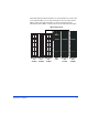
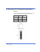
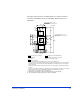
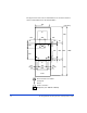
The figure below shows the recommended service clearance and floor
cutout recommendations for the XP1024 DKC. Measurements are in
millimeters.
Floor cutout area for cables
Caster
Screw jack
Service clearance
G
Grid panel (over 450mm x450mm)
Opening on the bottom of the frame
(for external cable entry)
(Unit : mm)
800
250
*2
250
*2
2400
680
55
65
113
123
564
Front
191
*2
191
2*
86
86
610
16
16
750
166
166
450
782
800
800
G
G
300
598
76
105
254
Recommended dimension : 400
( 300 – 602 ) *1
Recommended dimension : 300
( 250 - 400 ) *1
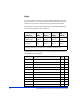
*1 Values of parenthesis show allowable range of the floor cutout dimension.
The floor cutout should be planned in the center of the DKC. In case that the floor cutout is planned
in a right position for the external cable work and it is within the allowable range,the cutout position
may be off-center.
In this case,check the relation between the positions of the cutout and the opening on the bottom of
the frame.
If the floor cutout width is planned more than 520 mm,be careful about the restriction of the movable
direction because there is a possibility that the caster wheels fall down into the cutout.
*2 These dimensions vary with the floor cutout dimension.
*3
*4
*3 The thickness of the front door (35 mm) is different from the rear door (25 mm).
*4 The overhang of the front door panel insert (7 mm) is not included.