HP StorageWorks Disk Arrays XP128/XP1024 Owner’s Guide fifth edition (July 2005) part number: A7906-96012 This guide describes the general operations, components, specifications, and options for the HP StorageWorks Disk Array XP128 and Disk Array XP1024.
© Copyright 2002-2005 Hewlett-Packard Development Company, L.P. All rights reserved. Hewlett-Packard Company makes no warranty of any kind with regard to this material, including, but not limited to, the implied warranties of merchantability and fitness for a particular purpose. Hewlett-Packard shall not be liable for errors contained herein or for incidental or consequential damages in connection with the furnishing, performance, or use of this material.
Contents About this guide 7 Related information 7 Document conventions and symbols 8 HP technical support 8 HP storage website 9 HP sales and authorized resellers 9 Helpful web sites 9 Revision history 10 1 2 Contents Overview 11 Continuous data availability 12 Nondisruptive service and upgrades Connectivity 14 Fibre Channel connectivity 14 ESCON connectivity 15 FICON connectivity 15 iSCSI connectivity 16 Data integrity 17 Summary of features 19 13 XP128 hardware 23 General safety guidelines 24 Physic
Powering down the disk array 37 Emergency power-off 37 Planned power-off 37 Recovering from a power outage to the disk array 39 Manual restart of the disk array after power is restored Automatic power on restart 40 Specifications 41 Temperature 41 Humidity 41 Mechanical vibration 42 AC line voltage 42 Web site 44 3 4 39 XP1024 hardware 45 General safety guidelines 46 Physical components 48 Disk control frame 51 Control panel 52 Service processor 52 Disk array frames 53 Available disk drives 54 RAID optio
4 Optional software products 77 XP array management 78 HP StorageWorks XP Remote Web Console and Command View Advanced Edition (AE) 78 Storage management and LUN security 79 HP StorageWorks LUN Configuration and Security Manager XP 79 Remote and local data replication 80 HP StorageWorks Continuous Access XP 80 HP StorageWorks Continuous Access Extension XP 80 HP StorageWorks Business Copy XP 80 Failover and load balancing 81 HP StorageWorks Auto Path XP 81 HP StorageWorks Secure Path 81 Performance managem
XP128 Declaration of Conformity 103 XP1024 Declaration of Conformity 104 European WEEE statements 105 Glossary Index 6 113 121 HP StorageWorks Disk Arrays XP128/XP1024 Owner’s Guide
About this guide This guide is for use by system administrators who have expertise in: • Disk arrays and RAID technology • Operating system commands and utilities • Data processing concepts • Direct-access storage device subsystems and their basic functions This document describes the general operations, components, specifications, and options for the HP StorageWorks Disk Array XP128 and XP1024. Unless otherwise noted, the term disk array refers to the HP StorageWorks XP128 and/or XP1024 Disk Array.
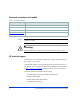
Document conventions and symbols Table 1. Document conventions Convention Element Blue text (Figure 1) Cross-reference links Bold Menu items, button names, key names, tab names, and group box names Italics Text emphasis and document titles Blue underlined sans serif font (www.hp.com) Web site addresses Caution Indicates that failure to follow directions could result in damage to equipment or data. Warning Indicates that failure to follow directions could result in injury or death.
• Operating system type and revision level • Detailed questions For continuous quality improvement, calls may be recorded or monitored. HP strongly recommends that customers sign up online using the Subscriber’s choice web site at http://www.hp.com/go/e-updates. Subscribing to this service provides you with email updates on the latest product enhancements, newest versions of drivers, and firmware documentation updates as well as instant access to numerous ohter product resources.
Revision history 10 May 2002 First Edition Oct.
1 Overview The Disk Array XP128 and Disk Array XP1024 are part of the HP StorageWorks Disk Array family of products. These disk arrays provide reliable and secure data storage and protection, featuring redundant circuitry and RAID storage options for data security. These disk arrays also support multiple operating systems, platforms, and RAID groups.
Continuous data availability The HP StorageWorks Disk Array XP family are the first RAID disk arrays to provide truly continuous data availability. They are designed for nonstop operation and continuous access to all user data. HP StorageWorks Disk Array XP128 and XP1024 disk arrays have no single point of component failure, which enables uninterrupted access to data.
Nondisruptive service and upgrades Monitoring software detects internal hardware component problems and notifies the HP Storage Technology Center automatically. At the support center, the problem is verified and the appropriate maintenance activity is executed by an HP service representative. The are no user serviceable components. Only an HP service representative should open the cabinets.
Connectivity The HP StorageWorks Disk Array XP128 and HP StorageWorks Disk Array XP1024 are connected to host systems using one of these types of connections: • Fibre Channel • ESCON • FICON • iSCSI Fibre Channel connectivity HP StorageWorks Disk Array XP128 The XP128 supports a maximum of three pairs of channel adapters that can support up to 48 Fibre Channel ports. Your disk array can support up to 8,192 LDEVs which can be configured as up to 24,576 LUNs through the Fibre Channel.
ESCON connectivity HP StorageWorks Disk Array XP128 The XP128 supports a maximum of three pairs of channel adapters that can support 24 ESCON ports for connection to mainframe hosts. The disk array can support up to 8,192 LDEVs. HP StorageWorks Disk Array XP1024 The XP1024 supports a maximum of six pairs of channel adapters that can support 48 ESCON ports for connection to mainframe hosts. The disk array can support up to 8,192 LDEVs.
iSCSI connectivity HP StorageWorks Disk Array XP128 The XP128 supports a maximum of three pairs of channel adapters that can support up to 24 iSCSI ports. The disk array can support up to 6,144 LDEVs through iSCSI. HP StorageWorks Disk Array XP1024 The XP1024 supports a maximum of four pairs of channel adapters that can support up to 32 iSCSI ports. Your disk array can support up to 8,192 LDEVs through iSCSI.
Data integrity HP disk arrays provide the highest levels of data integrity. This is accomplished using RAID technologies, together with redundant hardware throughout the disk array.
Some of the available software features and products that complement the disk array hardware are listed below: • HP StorageWorks Disk Array XP128 support “Phone Home” capability to the multidisciplinary Storage Technology Center advanced remote diagnostics full solution (Host-SAN-Storage) support • Full software and solution integration local and remote mirroring for online backup and disaster recovery (HP StorageWorks Business Copy XP and Continuous Access XP) security for multiple server consolidation (HP
Summary of features Table 2.
Table 2.
Table 2.
HP StorageWorks Disk Arrays XP128/XP1024 Owner’s Guide
2 XP128 hardware XP128 hardware 23
General safety guidelines Read the following safety guidelines carefully and follow them when you work with the HP StorageWorks Disk Array XP128 disk array. • Remember that the maintenance of your machine must be done only by trained and qualified HP field engineers. Only an HP service representative can power off the disk array in a non-emergency situation. • Please read and follow the safety guidelines and procedures in this manual and you other disk array manuals.
• Do not power off the system unless it is an emergency power-off situation. • Keep the front and rear doors closed at all times. • Keep the tops and sides of the cabinets clear to allow air to flow properly. • Do not perform any procedures not described in this document. If you have any questions or concerns, please contact your HP service representative. Warning Do not touch areas marked HAZARDOUS, even with the power off. These areas contain high-voltage power.
Physical components The HP StorageWorks Disk Array XP128 is a high-performance disk array system. It is used to store large quantities of data in an efficient and secure manner. Figure 1. HP StorageWorks Disk Array XP128 Your disk array has the following major hardware components: • Disk array cabinet The single disk array frame cabinet contains the control panel, connection hardware, the service processor, control boards and hard disk drives.
processor also collects performance data about the disk array for diagnostic testing and analysis. To ensure data security, the SVP does not have access to any user data stored on the disk array. • (Optional) second service processor This is available for users with extreme high availability requirements. This is not a required feature. • Control panel The control panel is your view of the disk array.
Device Manager server 1 XP128 Disk Array 2 Host Figure 2. The XP128 connections 1. The management station connects to the XP128 by means of a public LAN connection. The XP128 has an Ethernet connection for this purpose. 2. The host server uses a Fibre Channel, FICON, iSCSI, or ESCON connection.
Control panel Figure 3 and Table 3 on page 30 show the control panel and its functions, respectively.
Table 3. Control or indicator function on control panel Item Label Indicator Description 1 SUBSYSTEM READY LED (Green) Indicates that channel interface input/output operations are enabled. If the LED is off, the system is not accepting data. 2 SUBSYSTEM ALARM LED (Red) Indicates DC under voltage, DC over current, abnormally high temperature, or an unrecoverable failure. If your disk array is set up to report messages to the remote center, your HP service representative is notified automatically.
Table 3. Control or indicator function on control panel (Continued) Item Label Indicator Description 5 REMOTE MAINTENANCE PROCESSING LED (Amber) Indicates remote maintenance activity. An HP service representative is checking your system, but the system is online and accepting data. 6 REMOTE MAINTENANCE ENABLE/DISABLE Switch Used to permit remote service maintenance. Disable: No one can provide maintenance Enable: HP service representative can provide maintenance.
Table 3. Control or indicator function on control panel (Continued) Item Label Indicator 8 STORAGE CLUSTER 2 LED (Green) CHANNEL A-M Description Serial Channel/Fibre Channel: (1) On: Indicates some of the logical paths are established. U: UPPER (2) Fast blinking: Indicates the corresponding channel route is executing the channel command. (Only Serial Channel) L: LOWER (3) Slow blinking: Indicates none of the logical paths are established.
Table 3. Control or indicator function on control panel (Continued) Item Label Indicator Description 11 PWR SW ENABLE Switch Used to enable the PWR on/off switch. To enable the PWR on/off switch, turn the PWR SW ENABLE switch to the ENABLE position. If the automatic power on restart feature is not being used, this switch should be in the DISABLE (opposite of ENABLE) position during normal operation.
Emergency power-off A switch is provided on the control panel for an emergency powering off. See Figure 4 on page 35. If you detect an abnormal sound, smell, or smoke, power off the disk subsystem by operating the UNIT EMERGENCY POWER OFF switch following the procedure below. The procedure for operating the switch is as follows: 1. Push the operator panel cover at the location where PUSH is marked, open the operator panel cover, then operate the EMERGENCY POWER OFF switch. 2.
Figure 4.
Normal operations The disk array does not require user intervention. The disk array automatically reports any remote system information messages (R-SIMs) to your Device Manager server running HP Command View XP or Command View XP Advanced Edition, to the internal disk array service processor, and also to the HP Service Center. For more information on SIMs, see Chapter 5, "Troubleshooting" on page 87.
Powering down the disk array Situations may arise in the operation of the disk array that require you to power down the disk array. These situations include: • Emergency power-off • Planned power-off Emergency power-off An emergency is a critical situation such as a physical plant catastrophe. In an emergency, the critical need is to quickly remove power from the disk array. A quick restart is not necessary. In an emergency, the operator should trip the Emergency Power-Off (EPO) switch.
Caution Only a trained HP representative can shut down and power-off a disk array. Shutting down and powering off a disk array is not a customer activity. A user should not attempt to power down the disk array at any time other than an emergency. When planning for your planned power outage, please contact your HP CE to schedule a customer visit.
Recovering from a power outage to the disk array If AC input power is lost, the disk array maintains its state and recovers when power is restored. The array cache is backed up by batteries that will maintain its state for a minimum of 48 hours. This length of time will provide coverage for most outages. In cases where the outage will extend beyond 48 hours, the batteries can be replaced by a HP to extend the time, if necessary.
Automatic power on restart Caution As with all sophisticated electronic equipment, unstable power during a restart can induce problems. Hewlett-Packard recommends automatic power on restart only when the power to the disk array is conditioned to ensure stability (for example, using a UPS).
Specifications Some of the HP StorageWorks Disk Array XP128 disk array specifications are listed in this section. For a complete set of environmental specifications, refer to the HP Disk Array XP128 Site Prep Guide on the following main web site and access the appropriate support product: http://www.hp.com Temperature Table 4. Temperature Specifications Temperature Specification (Degrees F = 1.
Mechanical vibration Table 6. Mechanical vibration Mechanical vibration Maximum Operating Acceleration 0.05G at a frequency range of 10 to 300 Hz AC line voltage The following AC power recommendations for the HP StorageWorks Disk Array XP128 are for each power cord. Each array frame has two power cords (with the AC power cord option there are four cords). In case of a failure of the power source for one cord, the power requirements and the current requirement for the remaining power cord will double.
Table 8. 30-Amp, 50 or 60 Hz, Single-Phase DKC Operation Nominal Rated Voltage (VAC) Parameter 200 208* 220 230 240 Rated line current per power cord (Arms) 10.2 9.5 9.4 9.0 8.7 Number of power cords 4 4 4 4 4 Number of circuit breakers 4 4 4 4 4 30A 30A 30A 30A 30A Recommended circuit breakers * 60 Hz only. Table 9 (page 43) lists the basic AC power requirements for three-phase operation of the XP128 DKC. Table 9.
Web site For the most current support information on the HP StorageWorks Disk Array XP128, please visit the following main web site and access the appropriate support product: http://www.hp.
3 XP1024 hardware XP1024 hardware 45
General safety guidelines Read the following safety guidelines carefully and follow them when you work with your XP1024 disk array. • Remember that maintenance of your machine must be done only by trained and qualified HP field engineers. Only an HP service representative can power off the disk array. • Please read and follow the safety guidelines and procedures in this manual and any of your related manuals.
the disk subsystem by pulling the UNIT EMERGENCY POWER OFF switch on the disk subsystem. • Do not power off the system unless it is in an emergency power-off state. • Keep the front and rear doors closed at all times. • Keep the tops and sides of the cabinets clear to allow air to flow properly. • Do not perform any procedures not described in this document. If you have any questions or concerns, please contact your HP service representative.
Physical components The HP Disk Array XP1024 is a high-performance RAID-capable disk array system. It is used to store large quantities of data in an efficient and secure manner. Minimum Disk Subsystem DKU frame DKU frame DKC DKU frame DKU frame Figure 5.
. Minimum Disk Subsystem DKU frame (L3) 5th DKU DKU frame DKU frame (L2) (L1) 4th DKU 3rd DKU DKC frame DKU frame (R1) 1st DKU DKU frame (R2) 2nd DKU Figure 6. HP Disk Array XP1024 with HP Disk Array XP512 DKUs The maximum HDD configuration for an XP1024 with XP512 DKUs is 768. This is due to specifications for the 3 XP512 DKUs, which can contain a total of 256 HDDs (96+96+64).
The disk array has the following major hardware components: • One disk control frame (DKC) The single disk control frame cabinet contains the control panel, connection hardware, the service processor, and control boards for the disk arrays. • One to four XP1024 disk array frames (DKU) or • One to two XP1024 disk array frames and one to three XP512 DKU frames. The DKU cabinets contain your disk drives. When using only XP1024 DKUs, you can connect up to 4 DKUs.
Disk control frame The disk control frame controls your disk array. It provides you with a control panel, power supplies, controller boards, and your service processor. See Figure 7. Control Panel Figure 7. Disk Control Frame There is no single point of failure in the disk array. It is designed with redundant controllers and redundant power supplies, all of which can be removed or replaced without interrupting access to your data. Only your HP service representative can remove or replace hardware.
Control panel The control panel is your view to the disk array. Once the disk array is powered on and running normally, there are no user operations required at the control panel, except in case of a power failure recovery. The control panel will be discussed in further detail later in this chapter. Service processor The service processor (SVP) is a built-in PC connected inside the disk control frame. The SVP gives your HP service representative a method to access the software system on the disk array.
Disk array frames The disk array frames are where the physical disk drives, the disk groups, and any dynamic spare disk drives are located. You must have at least one disk array frame to operate the system, and you may have up to a maximum of four disk array frames installed on your system. If you have four disk array frames that are fully populated with disk drives, you will have a maximum of 149 TB. You may also have one to two XP1024 disk array frames grouped with one to three XP512 DKU frames.
DKU frame (L3) 5th DKU DKU frame (L2) 4th DKU DKU frame (L1) 3rd DKU DKU frame (R1) 1st DKU DKU frame (R2) 2nd DKU Figure 9. XP1024 and XP512 Disk Array Frames Available disk drives The disk array uses 3.5-inch disk drives, and a variety of disk capacities are available. Ask your HP service representative about currently available disk drives. Any of the disk drives in your disk array frames can be replaced without disrupting user activity.
RAID options Any of your spare disk drives can back up any other disk drive of the same or lesser capacity (and equal rotational speed), in any DKU frame, even if the failed disk and the spare disk are in different array domains, whether you are using RAID1 or RAID5 array groups. XP512 DKU Supported disk drives must have a spare drive in the XP512 DKU domain(s). Your disk arrays can be configured with a minimum of one and a maximum of 16 spare disk drives.
Table 10.
Control panel Figure 11 and Table 11 on page 58 show the control panel and its functions, respectively.
Table 11. Control panel functions Item Label Indicator Description 1 SUBSYSTEM READY LED (Green) Indicates that input/output operation on the channel interface is enabled. If the LED is off, the system is not accepting data. 2 SUBSYSTEM ALARM LED (Red) Indicates DC under voltage, DC over current, abnormally high temperature, or an unrecoverable failure has occurred. If your disk array is set up to report messages to the remote center, your HP service representative is notified automatically.
Table 11. Control panel functions Item Label Indicator Description 6 REMOTE MAINTENANCE ENABLE/DISABLE Switch Used to permit remote service maintenance. Disable: No one can provide maintenance Enable: HP service representative can provide maintenance. 7 STORAGE CLUSTER 1 LED (Green) CHANNEL A-R ENABLE Serial Channel/Fibre Channel: (1) On: Indicates some of the logical paths are established. (2) Fast blinking: Indicates the corresponding channel route is executing the channel command.
Table 11. Control panel functions Item Label Indicator Description 9 BS ON LED (Yellow) When the LED is on, unit is plugged in and receiving power from the primary AC outlet. The SVP is receiving power from the outlet. If BS is off, then the disk array is not receiving power from the primary AC outlet. Check the electrical outlets in your building. 10 PS ON LED (Green) When the LED is on power switch is on, the array is ready to receive data.
Table 11. Control panel functions Item Label Indicator Description 14 PWR ON/PWR OFF REMOTE/LOCAL Switch Determines how the disk array is powered on or off. REMOTE: Disk array is powered on/off by the instructions of the host power control interface (mainframe only). LOCAL: Disk array is powered on/off by the PWR ON/PWR OFF switch, 15 LED TEST/CHK RESET Switch LED TEST position: The LEDs on the panel go on. CHK RESET position: The PS ALARM and TH ALARMS is reset.
Emergency power-off A switch is provided on the operator panel on the front side of the disk control frame (DKC) for turning power off in an emergency. If you encounter any abnormality such as an abnormal sound, smell, or smoke, power off the disk subsystem by operating the UNIT EMERGENCY POWER OFF switch following the procedure below. The procedure for operating the switch is as follows: 1.
Figure 12.
Normal operations The disk array does not require intervention from the user. The disk array reports any remote system information messages (R-SIMs) to your Device Manager server running HP Command View XP or Command View XP Advanced Edition. The internal disk array service processor also sends the report to the HP Service Center automatically.
Powering down the disk array Situations may arise in the operation of the disk array that require the user to power down the disk array. These situations include: • Emergency power-off • Planned power-off Emergency power-off An emergency is a critical situation such as a physical plant catastrophe. In an emergency, the critical need is to quickly remove power from the disk array. A quick restart is not necessary.
Planned power-off There may be times when a site power outage is planned, such as to make alterations to the data center, do inspections, or to allow work by the electric company. If a scheduled power outage affects an HP Disk Array XP1024, the power down of the disk array must be scheduled with a trained HP support representative. Caution Only a trained HP representative may shut-down and power-off a disk array.
Recovering from a power outage to the disk array If a power outage to the array occurs, the disk array will maintain its state and recover when power is restored. The array cache is backed up by batteries that will maintain its state for a minimum of 48 hours. This length of time will provide coverage for most outages. In cases where the outage will extend beyond 48 hours, the batteries can be replaced by an HP CE which will extend the time, if necessary.
Manual restart of the disk array after power is restored Caution Before restoring power to the disk array, HP recommends that an electrician check the input power to ensure it is stable and clean. You may call a trained HP representative or you may use the following procedure yourself to recover the disk array from a power failure: 1. Move the ENABLE/DISABLE switch to the ENABLE position. Move the PWR ON/OFF switch to the PWR ON position. (Figure 11 on page 57, item 11/12) 2.
Automatic power on restart Caution As with all sophisticated electronic equipment, unstable power conditions during a restart can induce problems. HP recommends automatic power on restart only when power to the disk array is conditioned to ensure it is stable, such as by using a UPS.
Specifications Some of the XP1024 disk array specifications are listed in this section. Refer to the HP Disk Array XP1024 Site Prep Guide on the XP1024 web site at on the following main web site and access the appropriate product for a complete set of XP1024 specifications: http://www.hp.com Temperature Table 12. Temperature Specifications Temperature Specifications (Degrees F = 1.
AC line voltage requirements for the HP Disk Array XP1024 (DKC) Table 15 (page 71) lists the basic AC power requirements for a 40-amp, single-phase XP1024 DKC. Table 15. 40-Amp, 50 or 60 Hz, Single-Phase DKC Operation Nominal Rated Voltage (VAC) Parameter 200 208* 220 230 240 Rated line current per power cord (Arms) 8.0 7.7 7.2 7.0 6.6 Number of power cords 2 2 2 2 2 Number of circuit breakers 2 2 2 2 2 Recommended circuit breakers 40 A 40A 40A 40A 40A * 60 Hz only.
Table 17 (page 72) lists the basic AC power requirements for a 30-amp, three-phase XP1024 DKC. Table 17. 30-Amp, 50 or 60 Hz, Three-Phase DKC Operation Nominal Rated Voltage (VAC) Parameter 200 2081 220 230 240 380 400 415 Rated line current per 5.2 power cord (Arms) 5.0 4.7 4.6 4.3 2.7 2.6 2.5 Number of power cords 2 2 2 2 2 2 2 2 Number of circuit breakers 2 2 2 2 2 2 2 2 Recommended circuit breakers 30 A 30 A 30 A 30 A 30 A 30 A 30 A 30 A * 60 Hz only.
AC line voltage requirements for the HP Disk Array XP1024 (DKU) Table 18 (page 73) lists the basic AC power requirements for a 50-amp, single-phase, XP1024 DKU. Table 18. 50-Amp, 50 or 60 Hz, Single-Phase DKU Operation Nominal Rated Voltage (VAC) Parameter 200 208* 220 230 240 Rated line current per power cord (Arms) 22.3 21.6 20.3 19.4 18.6 Number of power cords 2 2 2 2 2 Number of circuit breakers 2 2 2 2 2 Recommended circuit breakers 50 A 50 A 50 A 50 A 50 A * 60 Hz only.
Table 20 (page 74) lists the basic AC power requirements for a 60-amp, three-phase XP1024 R1 DKU. Table 20. 60-Amp, 50 or 60 Hz, three-phase R1 DKU operation Nominal Rated Voltage (VAC) Parameter 200 2081 220 230 240 380 400 415 Rated line current per 19.0 18.2 17.2 16.6 15.7 10.7 10.2 9.8 power cord (Arms) Number of power cords 2 2 2 2 2 2 2 2 Number of circuit breakers 2 2 2 2 2 2 2 2 Recommended circuit breakers 60 A 60 A 60 A 60 A 60 A 30 A 30 A 30 A min2 min2 min2 1.
Table 22 (page 75) lists the basic AC power requirements for a 30-amp, three-phase XP1024 DKU. Table 22. 30-Amp, 50 or 60 Hz, three-phase DKU operation Nominal Rated Voltage (VAC) Parameter 200 208* 220 230 240 380 400 415 Rated line current per 15.0 14.4 13.6 13.0 12.5 8.8 power cord (Arms) 8.4 8.1 Number of power cords 2 2 2 2 2 2 2 2 Number of circuit breakers 2 2 2 2 2 2 2 2 Recommended circuit breakers 30 A 30 A 30 A 30 A 30 A 30 A 30 A 30 A * 60 Hz only.
HP StorageWorks Disk Arrays XP128/XP1024 Owner’s Guide
4 Optional software products Several optional HP software packages are available to increase your data accessibility and enable continuous access to user data on the disk array. This chapter describes how these optional software applications can help you run your disk array system. Before installing the optional software packages, refer to the package’s manual to verify equipment requirements.
XP array management HP StorageWorks XP Remote Web Console and Command View Advanced Edition (AE) Remote Web Console (RWC) is the standard management software package for the XP disk array. It provides a web-based interface for managing one disk array and is built into the SVP. To access RWC, you open a browser and enter the IP address of the SVP. RWC allows you to install and manage the disk array but does not allow you to manage multiple arrays.
Storage management and LUN security HP StorageWorks LUN Configuration and Security Manager XP LUN Configuration Manager comes with three applications that are executed from Remote Web Console XP or StorageWorks Command View XP.
Remote and local data replication Continuous Access XP, Continuous Access Extension XP, and Business Copy XP are valuable tools for creating copies of data for testing, backup, and disaster recovery. HP StorageWorks Continuous Access XP Continuous Access allows you to make ongoing synchronous copies of disk array data to a remote site 27 miles (43 kilometers) away.
Failover and load balancing HP StorageWorks Auto Path XP Using Auto Path XP, you can enable Windows NT server I/O path failover and load balancing control for dual path connections. You can configure up to eight multiple paths per LUN that will provide automatic and transparent failover in the event of path failure. You can also enable dynamic, multi-path load balancing to prevent overloaded I/O operations.
Performance management HP StorageWorks Cache LUN XP Cache LUN XP enables you to reserve disk array cache memory for storing high-use data, greatly increasing access speed to that data. HP StorageWorks Auto LUN XP Auto LUN XP provides monitoring and disk usage analysis for your disk array based on user thresholds. Auto LUN develops a plan to migrate impacted data volumes to lower usage LUNs, using the data acquired during monitoring. You can perform the migration manually or automatically.
HP StorageWorks Application Policy Manager XP HP StorageWorks Application Policy Manager XP is a performance allocation and management tool for XP disk arrays. It lets you allocate storage performance resources to hosts by means of policies you define. It ensures that critical business processes have all the XP disk array performance they need to meet business objectives. You can ensure that processes such as backups and data warehouse loads get the array bandwidth necessary to meet deadlines.
Network management products HP OpenView SPI for XP Disk Arrays HP OpenView SPI for XP Disk Arrays establishes an agent that monitors XP disk arrays, provides a correlation of events on the disk arrays, and then forwards those events to the OpenView Operations management console.
Mainframe solutions HP StorageWorks Resource Manager XP HP StorageWorks Resource Manager XP allows you to share data stored on the disk array with mainframe systems and open system servers. This can reduce and optimize your storage maintenance and management overhead. HP StorageWorks Resource Manager XP allows an XP array to connect to a mainframe system via an ESCON link.
HP StorageWorks Disk Arrays XP128/XP1024 Owner’s Guide
5 Troubleshooting This chapter explains the monitoring and reporting capabilities and the flow of troubleshooting used on the HP StorageWorks Disk Array family of disk arrays.
Monitoring and reporting The disk array generates service information messages (SIMs) to identify normal operations, service requirements, and failures. SIMs can be generated on the disk array by the CHIP (Client Host Interface Processor) and ACP (Array Control Processor) microprocessors and by the internal service processor (SVP). Your HP service representative will use the SIMs to monitor and troubleshoot your disk array.
Troubleshooting flow diagram When the system encounters trouble, it will report the trouble to the HP Storage Technology Center. If a failure occurs in the disk array, it is detected and reported to the system log, the SIM log, and the HP Storage Technology Center. Figure 13 is a flow diagram that explains the progress of error detection and reporting. 1. A failure is detected in your disk array. 2. The failure is reported to the system. 3. The system stores the failure information in the system log.
4 HP Storage Stress Free Technology CentralCenter 1 2 Failure 3 SSB SIM SSB Log SIM Log SSB SIM RC Figure 13.
6 Regulatory statements The following regulatory statements apply to the HP Disk Array XP128 and XP1024.
FCC EMC Statement (USA) This equipment has been tested and found to comply with the limits for a Class A digital device, pursuant to Part 15 of the FCC rules. These limits are designed to provide reasonable protection against harmful interference when the equipment is operated in a commercial environment. This equipment generates, uses, and can radiate radio frequency energy and, if not installed and used in accordance with the instruction manual, may cause harmful interference to radio communications.
IEC Statement (Worldwide) This is a Class A product. In a domestic environment this product may cause radio interference, in which case the user may be required to take adequate measures.
EMC Statement (Canada) This Class A digital apparatus meets all requirements of the Canadian Interference-Causing Equipment Regulations. Cet appareil numérique de la Classe A respecte toutes les exigences du Règlement sur le matériel brouilleur du Canada.
Spécification ATI Classe A (France) DECLARATION D'INSTALLATION ET DE MISE EN EXPLOITATION d'un matériel de traitement de l'information (ATI), classé A en fonction des niveaux de perturbations radioélectriques émis, définis dans la norme européenne EN 55022 concernant la Compatibilité Electromagnétique.
VCCI EMC Statement (Japan) 96 HP StorageWorks Disk Arrays XP128/XP1024 Owner’s Guide
BSMI EMC Statement (Taiwan) Regulatory statements 97
RRL EMC Statement (Korea) 98 HP StorageWorks Disk Arrays XP128/XP1024 Owner’s Guide
Harmonics Conformance (Japan) Regulatory statements 99
German Noise Declaration XP10000: Schalldruckpegel Lp = 70 dB(A) Am Arbeitsplatz (operator position) Normaler Betrieb (normal operation) Nach ISO 7779:1988 / EN 27779:1991 (Typprüfung) 100 HP StorageWorks Disk Arrays XP128/XP1024 Owner’s Guide
Laser Safety When equipped with native Fibre Channel adapters or iSCSI adapters, this product contains a laser internal to the Optical Link Module (OLM) contained on the 4-port Fibre Channel Adapter board and 4-port FICON board, the 8-port Fibre Channel Adapter board and 8-port FICON board, and the 4-port iSCSI board for connection to a fiber communications network.
Japan DENAN law cordset caution Please use the supplied power cord. The power cord may not be used with other products.
XP128 Declaration of Conformity Regulatory statements 103
XP1024 Declaration of Conformity 104 HP StorageWorks Disk Arrays XP128/XP1024 Owner’s Guide
European WEEE statements Czech Danish Regulatory statements 105
Dutch English Estonian 106 HP StorageWorks Disk Arrays XP128/XP1024 Owner’s Guide
Finnish French German Regulatory statements 107
Greek Hungarian 108 HP StorageWorks Disk Arrays XP128/XP1024 Owner’s Guide
Italian Latvian Lithuanian Regulatory statements 109
Polish Portuguese Slovak 110 HP StorageWorks Disk Arrays XP128/XP1024 Owner’s Guide
Slovenian Spanish Swedish Regulatory statements 111
HP StorageWorks Disk Arrays XP128/XP1024 Owner’s Guide
Glossary ACP Array control processor. The ACP handles the passing of data between the cache and the physical drives held in the DKUs. ACPs work in pairs, providing a total of eight SCSI buses. Each SCSI bus associated with one ACP is paired with a SCSI bus on the other ACP pair element. In the event of an ACP failure, the redundant ACP takes control. Both ACPs work together sharing the load. AL Arbitrated loop. AL-PA Arbitrated loop physical address.
C-Track The HP StorageWorks Continuous Track XP software program, which detects internal hardware component problems on a disk array and automatically reports them to the HP STC. CA The HP StorageWorks Continuous Access XP program, which enables you to replicate data stored on a local disk array to a remote disk array. cache Very high speed memory that is used to speed I/O transaction time. All reads and writes to the XP array family are sent to the cache.
CU Control unit. CVS Custom volume size. CVS devices (OPEN-x CVS) are custom volumes configured using array management software to be smaller than normal fixed-size OPEN system volumes. Synonymous with volume size customization (VSC). disk adapter (DKA) Synonymous with the term ACP. disk unit (DKU) The array hardware that houses the disk array physical disks. disk controller (DKC) The array hardware that houses the channel adapters and service processor (SVP).
The LUSE feature is available when the HP StorageWorks LUN Configuration Manager product is installed. ExSA Extended serial adapter. failover Disconnecting a failed unit or path and replacing it with an alternative unit or path in order to continue functioning. FC Fibre Channel. FC-AL Fibre Channel arbitrated loop. FCP Fibre Channel Protocol. fence level A level for selecting rejection of a write I/O request from the host according to the condition of mirroring consistency.
LED Light emitting diode. local disk A disk in the host. LU Logical unit. LUN Logical unit number. A LUN results from mapping a SCSI logical unit number, port ID, and LDEV ID to a RAID group. The size of the LUN is determined by the emulation mode of the LDEV, and the number of LDEVs associated with the LUN. For example, a LUN associated with two OPEN3 LDEVs has a size of 4,693 MB. LUSE Logical unit size expansion. See also Expanded LUN. m Meters. MB Megabytes. MCU Main control unit.
OS Operating system. PA Physical address. parity group A parity group is a disk configuration in which multiple disks work together to provide redundancy. Synonymous with “array group.” partition Dividing a specific physical disk into two or more areas as if there are two or more physical disks. path Paths are created by associating a port, a target, and a LUN ID with one or more LDEVs. PCI Power control interface or peripheral component interconnect.
RM HP StorageWorks RAID Manager XP, a command line interface for managing XP arrays. R-SIM Remote service information message. R/W, r/w Read/write. script file A file containing a shell script. SCSI Small computer system interface. shell script A command sequence executed by a UNIX shell. sidefile An area of cache used to store the data sequence number, record location, record length, and queued control information. SIM Service information message.
HP StorageWorks Disk Arrays XP128/XP1024 Owner’s Guide
Index A authorized reseller, HP 10 authorized resellers 9 B browser-based console Command View XP Advanced Edition 78 Remote Web Console XP 78 C Command View XP Advanced Edition 78 connectivity ESCON connectivity 15 Fibre Channel connectivity 14 conventions, document 8 core solutions Cache LUN XP 82 D data integrity hardware features 17 software and solution integration 18 software features/products 18 support 18 Device Manager server (formerly Management Console PC) 55 Index disaster recovery Continuous
documentation audience 7 conventions 8 for related products 7 related 7 E Emergency power-off 37, 65 Emergency power-off switch 65 environmental specifications AC line voltage 42 humidity 41, 70 mechanical vibration 42 temperature 41, 70 EPO switch 65 F failover & load balancing Auto LUN XP 82 Auto Path XP 81 H hardware available disk drives 54 disk array frames 50, 53 disk control frame 26, 28, 50, 51 emergency power-off 34, 62 major hardware components 27 normal operations 36, 64 operator control panel 29
optional software Auto LUN XP 82 Auto Path XP 81 Business Copy XP 80 Cache LUN XP 82 Command View XP Advanced Edition 78 Continuous Access Extension XP 80 Continuous Access XP 80 Data Exchange XP 85 OpenView/ITO SPI 84 Remote Web Console XP 78 Resource Manager XP 85 Secure Manager XP 79 P physical components disk array frames 53 disk control frame 28, 51, 52 emergency power-off 34, 62 major hardware components 27 normal operations 36, 64 operator control panel 29, 57 Power-off emergency 37, 65 normal 37, 66
web site HP storage 9 HP support 8 web-based console Command View XP Advanced Edition 78 Remote Web Console XP 78 X XP1024 second service processor 50 XP128 second service processor 27 XP48 disk array safety 24 XP512 DKU Diagram 54 124 HP StorageWorks Disk Arrays XP128/XP1024 Owner’s Guide