HP StorageWorks XP24000 SNMP Agent Reference Guide Part number: AE131–96006 First edition: June 2007
Legal and notice information © Copyright 2007 Hewlett-Packard Development Company, L.P. Confidential computer software. Valid license from HP required for possession, use or copying. Consistent with FAR 12.211 and 12.212, Commercial Computer Software, Computer Software Documentation, and Technical Data for Commercial Items are licensed to the U.S. Government under vendor's standard commercial license. The information contained herein is subject to change without notice.
Contents About this Guide . . . . . . . . . . . . . . . . . . . . . . . . . . Intended Audience . . . . . . . . . . Related Documentation . . . . . . . . Document Conventions . . . . . . . . Conventions for Storage Capacity Values Window Illustrations . . . . . . . . . HP Technical Support . . . . . . . . . Subscription Service . . . . . . . . . HP Websites . . . . . . . . . . . . Documentation Feedback . . . . . . . . . . . . . . . . . . . . . . . . . . . . . . . . . . . . . . . . . . . . . . . . . .
MIB Mounting Specifications . . . . . . . Extension MIB Specifications . . . . . . . . . Extension MIB Configuration . . . . . . . raidExMibName . . . . . . . . . . . raidExMibVersion . . . . . . . . . . raidExMibAgentVersion . . . . . . . . Number of Disk Controllers under Control raidExMibRaidList . . . . . . . . . . (raidlistEntry) . . . . . . . . . . . . raidExMibDKCHW . . . . . . . . . dkcHWEntry . . . . . . . . . . . . raidExMibDKUHW . . . . . . . . . dkuHWEntry . . . . . . . . . . . . raidExMibDKCHW2 .
Figures 1 ..SNMP Environment . . . . . . . . . . . . . . . . . . . . . . . . . . . . . . . . 9 2 ..SNMP Environment Architecture . . . . . . . . . . . . . . . . . . . . . . . . . 11 3 ..Example of SNMP Operations . . . . . . . . . . . . . . . . . . . . . . . . . . 12 4 ..SNMP Information Tab . . . . . . . . . . . . . . . . . . . . . . . . . . . . . 5 ..Adding SNMP Manager IP Address (Top: Before Setting, Bottom: After Setting) . . . . . 15 18 6 ..Delete IP Address Pop-Up Menu . . . . . . . . . . . . . . .
Tables 1 ..Document Conventions . . . . . . . . . . . . . . . . . . . . . . . . . . . . . . 7 2 ..Available Component Status Information . . . . . . . . . . . . . . . . . . . . . 10 3 ..Subsystem Component Status Types . . . . . . . . . . . . . . . . . . . . . . . . 10 4 ..SNMP Trap Triggering Events . . . . . . . . . . . . . . . . . . . . . . . . . . 13 5 ..SNMP Agent Operations . . . . . . . . . . . . . . . . . . . . . . . . . . . . 13 6 ..SNMP Agent REQUEST Operations . . . . . . . . . . . . . . .
About this Guide The HP StorageWorks XP24000 SNMP Agent Reference Guide describes the SNMP Agent interface for the HP storage system. Please read this manual carefully to understand how to manipulate your storage systems using the Remote Web Console software, and maintain a copy that is accessible from the Remote Web Console computer for reference purposes. The term storage system in this guide refers to an HP StorageWorks XP24000 Disk Array.
• 1 TB (terabyte) = 1,0004 bytes HP XP storage systems use the following values to calculate logical storage capacity values (logical devices): • • • • • 1 1 1 1 1 KB (kilobyte) = 1,024 bytes MB (megabyte) = 1,0242 bytes GB (gigabyte) = 1,0243 bytes TB (terabyte) = 1,0244 bytes block = 512 bytes Window Illustrations The windows shown in this guide were displayed on a Windows computer with the Internet Explorer browser.
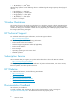
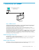
1 Overview of SNMP Network Management Station (SNMP Manager) Managed Device (SNMP Agent) Figure 1 SNMP Environment Simple Network Management Protocol (SNMP) is an industry-standard the protocol for managing and monitoring network devices, including disk devices, routers, and hubs. SNMP uses Simple Gateway Management Protocol (SGMP) to manage the TCP/IP gateways. The standardized configuration and database of network management information is called a Management Information Base (MIB).
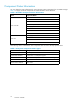
Component Status Information You can obtain the status information for certain storage system components from an SNMP manager. Table 2 on page 10 lists the components for which the status can be obtained. Table 2 Available Component Status Information Area Component Name Processor BUS Cache Disk Controller Shared memory Power supply Battery Fan Others Power supply Disk Unit Fan Others Drive The following status is indicated for each component status as well as the trap report function.
2 About SNMP Operations System Configuration The SNMP agent for the HP storage system is on the service processor (SVP), which is the computer within the storage array that manages the disk controller (DKC). The storage system has an exclusive LAN for communications between a disk controller and a service processor, and a separate LAN for SNMP. The configuration of each Network Management Station is determined by the type of SNMP Manager. Figure 2 on page 11 illustrates the SNMP environment.
SNMP Manager SNMP Agent GET REQUEST GET RESPONSE GETNEXT REQUEST GET RESPONSE TRAP Figure 3 Example of SNMP Operations Management Information Base (MIB) Each managed device has certain types of information, including the configuration information, the status information for device, and statistical, which is known collectively as a Management Information Base (MIB).
Table 4 SNMP Trap Triggering Events Events Description Acute failure detected. All operations in a subsystem stopped. Serious failure detected. Operation in a component where a failure occurred stopped. Moderate failure detected. Partial failure. Service failure detected. Minor failure. An SNMP agent logs the most recent 256 traps, so you can see the trap history of a particular device. SNMP Agent Command Table 5 on page 13 shows the types SNMP Agent operations.
• SNMP uses the TCP/IP User Datagram Protocol (UDP). If the SNMP agent doesn’t respond within a specified time period, the SNMP manager re-sends the request packet. That time period is set by the system administrator, taking into account the network traffic and operation policy. • If an SNMP agent again does not respond to the re-sent packet, the SNMP manager assumes that an error has occurred. Depending on the times set for polling and response, this can take several seconds.
3 Using the SNMP GUI SNMP Information Tab The SNMP Information tab allows you to extend the number of LUs and cache memory using Just in Time Storage. Click Go – Environmental Settings – SNMP Information in the menu bar of Remote Web Console Main window. The SNMP Information tab displays. Select the SNMP Information tab (see Figure 4 on page 15). Note: Option buttons (left side of the window) and subsystem information icons (window upper right corner) have been omitted from the screen shot.
• • • • 16 • Set: Adds new IP addresses to the IP Address list box. Community & Trap allows you to add, delete, or change SNMP trap information. The registered IP address is the trap destination for the specified community. • Each community can have more than one defined IP ad dress (sees “Adding a Community Name” on page 19 and “Adding Community IP Addresses” on page 21). • You can register up to 32 community names and up to 32 IP addresses per community name.
4 Performing SNMP Operations Adding SNMP Manager IP Addresses To add SNMP Manager IP addresses: 1. Log on to open Remote Web Console Main window. Change to Modify mode (see HP StorageWorks XP24000 Remote Web Console User’s Guide if you need instructions). 2. Click Go – Environmental Settings – SNMP Information in the menu bar of Remote Web Console Main window. The SNMP Information window is displayed (see Figure 4 on page 15). 3.
Figure 5 Adding SNMP Manager IP Address (Top: Before Setting, Bottom: After Setting) Deleting SNMP Manager IP Addresses To delete an SNMP Manager IP address: 1. Change to Modify mode. 2. Log on to Remote Web Console. Click Go – Environmental Settings – SNMP Information in the menu bar of Remote Web Console Main window. The SNMP Information window is displayed (see Figure 4 on page 15). 3. Select one or more unwanted IP addresses in IP Address list box.
Figure 6 Delete IP Address Pop-Up Menu Adding a Community Name To add a community name: 1. Change to Modify mode. 2. Log on to Remote Web Console. Click Go – Environmental Settings – SNMP Information in the menu bar of Remote Web Console Main window. The SNMP Information window is displayed (see Figure 4 on page 15). 3. In Community &Trap box, select and right-click Community. Add Community pop-up menu displays (see Figure 7 on page 19). 4. Select Add Community.
Figure 8 Add Community dialog box Deleting a Community Name To delete a community name: 1. Change to Modify mode. 2. Log on to open Remote Web Console Main window, click Go – Environmental Settings – SNMP Information in the menu bar of Remote Web Console Main window. The SNMP Information window is displayed (see Figure 4 on page 15). 3. In Community & Trap, select and then right-click the unwanted community. The Delete Community popup menu displays (see Figure 9 on page 20). 4.
3. Select and then right-click the community name that you want to change in Community & Trap. The Change Community popup menu displays (see Figure 10 on page 21). 4. Select Change Community. The Change Community dialog box displays (see Figure 11 on page 21). 5. In the Community text box, overwrite the old community name with a new community name. You can use up to 180 alphanumeric characters, except for ", \, ;, :, ,, *, ?, <, >, |, /, ^, &, and %.
5. Select OK. The new IP address displays in Community & Trap, but the change is not yet implemented. 6. Select Apply. Select OK or Cancel. Figure 12 Add IP Address Pop-Up Menu Figure 13 IP Address dialog box Deleting a Community IP Address To delete a community IP address: 1. Change to Modify mode. 2. Log on to Remote Web Console. Click Go – Environmental Settings – SNMP Information in the menu bar of Remote Web Console Main window. The SNMP Information window is displayed (see Figure 4 on page 15). 3.
Figure 14 Delete Community IP Address Pop-Up Menu XP24000 SNMP Agent Reference Guide 23
Performing SNMP Operations
5 SNMP Supported MIB Trap Configuration Extension Trap Specifications The specifications of the supported extension trap are as follows. Table 7 Extension Trap Specifications Operation Specification Mounting Value SNMP Community Specified community name — Protocol Data Unit (PDU) Type Trap PDU 4 Enterprise ID Agent Identifier 1.3.6.1.4.1.116.3.11.4.1.1 Agent IP Address Agent IP Address — Generic Trap Code EnterpriseSpecific — Specific Trap Code See Table 8 on page 25.
Table 9 Failure Report Trap Name Object Identifier Type Description EventTrapSerialNumber 1.3.6.1.4.1.116.5.11.4.2.1 INTEGER The product number of the device that experienced the failure. EventTrapNickname 1.3.6.1.4.1.116.5.11.4.2.2 DisplayString The device nickname. EventTrapREFCODE 1.3.6.1.4.1.116.5.11.4.2.3 DisplayString The failure reference (see Table 8 on page 25). EventTrapPartsID 1.3.6.1.4.1.116.5.11.4.2.4 OBJECT IDENTIFIER The area where the failure occurred (Note).
root - iso(1) - org(3) - dod(6) - internet(1) - mrmt(2) - mib-2(1) - system(1) Standard MIB MIB-II - private(4) - enterprises(1) Figure 15 Object System (1) Figure 16 Object System (2) Figure 17 Object System (3) Supported Traps Table 11 on page 28 shows the supported trap types.
Table 11 Extension Trap Types Specific Trap Code Trap Description 1 RaidEventUserAcute All operations in a subsystem stopped. 2 RaidEventUserSerious Operation in a component where a failure occurred stopped. 3 RaidEventUserModerate Partial failure. 4 RaidEventUserService Minor failure.
raidExMibRoot(1) - raidExMibName(1) SVP Product Name - raidExMibVersion(2) SVP Micro-program Version - raidExMibAgentVersion(3) Extension MIB Internal Version - raidExMibDkcCount(4) Number of DKC Under the Control of SVP - raidExMibRaidList(5) List of DKC Under the Control of SVP - raidExMibDKCHW(6) Disk Control Device Information - raidExMibDKUHW(7) Disk Device Information - raidExMibTrapList(8) Error Information List - raidExMibDKCHW2(70) Disk Control Device Information2 Figure 18 Extens
Number of Disk Controllers under Control of SVP (raidExMibDkcCount) raidExMibDkcCount suggests the number of a disk controller under the control of SVP. raidExMibRaidList raidExMibRaidList indicates the subsystem under the control of the SVP.
Table 13 on page 31 shows the type of information displayed for each subsystem Table 13 Subsystem Information Name Type Description Mounted Value Attribute raidlistSerialNumber ::=raidlistEntry(1) INTEGER Disk controller product number (index). 1-99,999 read-only raidlistMibNickName ::=raidlistEntry(2) DisplayString Disk controller nickname. (Max. 18 characters) read-only raidlistDKCMainVersion ::=raidlistEntry(3) DisplayString Microcode version. (Max.
Table 14 on page 32 describes the status of the subsystem components Table 14 Subsystem Component Information Name Type Description MIB Value Attribute DKCRaidListIndexSerialNumber ::=dkcHWEntry(1) INTEGER Disk controller product number (index). 1-99,999 read-only DKCHWProcessor ::=dkcHWEntry(2) INTEGER Status of processor. DKCHWCSW ::=dkcHWEntry(3) INTEGER Status of internal star. DKCHWCache ::=dkcHWEntry(4) INTEGER Status of cache.
dkuHWEntry dkuHWEntry indicates the status of the disk unit components. Table 15 Disk Device Components Information Name Type Description MIB Value Attribute DKURaidListIndexSerialNumber ::=dkuHWEntry(1) INTEGER Disk controller product number (index). 1-99,999 read-only DKUHWPS ::=dkuHWEntry(2) INTEGER Status of power supply. DKUHWFan ::=dkuHWEntry(3) INTEGER Status of fan. DKUHWEnvironment ::=dkuHWEntry(4) INTEGER Status of environment monitor.
raidExMibDKCHW2 raidExMibDKCHW2 indicates the status of the subsystem components. Table 16 Subsystem Components Information 2 Name Type Description MIB Value Attribute DKC2RaidListIndexSerialNumber ::=dkcHW2Entry(1) INTEGER Disk controller product number (index). 1-99,999 read-only DKCHW2Environment ::=dkcHW2Entry(2) INTEGER Information about environmental failure. DKCHW2SVP ::=dkcHW2Entry(3) INTEGER Status of SVP. DKCHW2PP ::=dkcHW2Entry(4) INTEGER Status of program product failure.
Table 17 Failure Information Name Type Description MIB Value Attribute EventListIndexSerialNumber ::=eventTrapEntry(1) INTEGER Disk controller product number (index). 1-99,999 read-only EventListNickname ::=eventTrapEntry(2) DisplayString Disk controller nickname. (Max. 18 characters) read-only EventListIndexRecordNo ::=eventTrapEntry(3) Counter Number of record. 1-256 read-only EventListREFCODE ::=eventTrapEntry(4) DisplayString Reference code.
Figure 19 Extension MIB Configuration (1) 36 SNMP Supported MIB
cÆ - raidExMibRoot(1) - raidExMibName(1) - raidExMibVersion(2) - raidExMibAgentVersion(3) - raidExMibDkcCount(4) - raidExMibRaidList(5) - raidlistEntry(1) - raidlistSerialNumber(1)* - raidlistMibNickName(2) - raidlistDKCMainVersion(3) - raidlistDKCProductName(4) - raidExMibDKCHW(6) - dkcHWEntry(1) - DKCRaidListIndexSerialNumber(1)* - DKCHWProcessor(2) - DKCHWCSW(3) - DKCHWCache(4) - DKCHWSM(5) - DKCHWPS(6) - DKCHWBattery(7) - DKCHWFan(8) - DKCHWEnvironment(9) - raidExMibDKUHW(7) - dkuHWEntry(1) - DKURaidLi
SNMP Supported MIB
6 SNMP Failure Trap Reference Table 18 on page 39 shows the alert level, the trap reference code, the description, and the alert level.
Trap Reference Code Description Alert Level SIM22 SIM23 SIM13 FF C3 0x Cache Package Blockade processing finished SERVICE FF F1 xy Cache temporary failure SERVICE FF F2 xy Module blockade MODERATE FF F3 0x Package blockade MODERATE FF F4 0x Module group blocking SERIOUS FF E2 0x Area blocking FF E9 01 HP StorageWorks XP for Compatible Parallel Access Volumes Software microcode volatilization SERIOUS FF EA 0x Recovery of area blocked temporarily was completed SERVIC
Trap Reference Code Description Alert Level SIM22 SIM23 SIM13 AC 50 xy HDU power supply shutdown detected Power supply (DKU) MODERATE 14 00 x0 Ethernet error for SVP DKC environment MODERATE 14 01 x0 Failure during SIM transfer to SVP SERIOUS 15 00 x0 Ethernet error for SVP MODERATE 15 01 x0 Failure during SIM transfer to SVP SERIOUS BF 1x 1x Abnormal temperature MODERATE BF 2x 1x Alarm for voltage BF 4x 1x Warning for power supply BF 5x 1x Warning for batter
Trap Reference Code Description Alert Level SIM22 SIM23 SIM13 D0 8x xx Waiting for periodic copying SERVICE D0 9x xx Periodic copying finished SERVICE D0 Ax xx Update I/O received after periodic copying finished xx Status change according to the PPRC pair status change assignment from MCU (Simplex->Duplex Pend) SERVICE 1x xx Status change according to the PPRC pair status change assignment from MCU (Simplex->Duplex) SERVICE 2x xx Status change according to the PPRC pair status cha
Trap Reference Code SIM22 SIM23 Description Alert Level SERVICE SERVICE SIM13 D1 Bx xx Status change according to the PPRC pair status change assignment from MCU (Suspend [Continue] -> Suspend) D3 0x xx Migration copy start D3 1x xx Migration copy normal end D3 2x xx Receipt of pair status end (Migration copy/ERASE) SERVICE D4 0x xx Pair suspend due to RIO path blockade SERIOUS D4 1x xx Pair suspend due to failure detected in M-VOL SERIOUS D4 2x xx Pair suspend due to fai
Trap Reference Code SIM22 D5 D5 D5 SIM23 3x 4x 5x Description Alert Level SIM13 yy TrueCopy for Mainframe volume has received a request for suspending a pair. The request was made by the SVP, an Remote Web Console computer, or a host. x: The CU number yy: The LDEV number yy TrueCopy for Mainframe pair has been deleted. x: The CU number yy: The LDEV number SERVICE yy TrueCopy for Mainframe pair has been suspended.
Trap Reference Code Description Alert Level SIM22 SIM23 SIM13 D9 2x xx Request for changing S-VOL status has been received from MCU (COPY -> PAIR) D9 3x xx Request for changing S-VOL status has been received from MCU (COPY -> PSUS) SERVICE D9 4x xx Request for changing S-VOL status has been received from MCU (PAIR -> PSUS) SERVICE D9 5x xx Request for changing S-VOL status has been received from MCU (PAIR -> SMPL) SERVICE D9 6x xx Request for changing S-VOL status has been receiv
Description Alert Level yy A currently used M-VOL has been suspended because an operation for suspending an R-VOL was performed. x: The CU number yy: The LDEV number SERIOUS yy A currently used M-VOL has been suspended because an operation for deleting a pair was performed on an R-VOL. x: The CU number yy: The LDEV number SERIOUS yy A currently used R-VOL has been suspended because an unrecoverable failure occurred in the remote copy connection.
Trap Reference Code Description Alert Level SIM22 SIM23 SIM13 DC 6x xx Volume used as S-VOL has been suspended (Unable to restore path) SERIOUS DC 7x xx Volume used as S-VOL has been suspended (RCU failure detected) SERIOUS SERIOUS DC 9x yy Volume used as a P-VOL of Delta resync has been suspended x: The CU number yy: The LDEV number 47 Ax xx Copying ended with warning MODERATE 47 Dx xx Copying ended abnormally MODERATE 47 E5 xx HP StorageWorks XP for FlashCopy Mirroring So
Trap Reference Code SIM22 SIM23 SIM13 62 0x xx Description Alert Level Exceeded the XP Thin Provisioning volume usage threshold. MODERATE The SIM Code for TrueCopy for Mainframe errors is determined by the mode. See Table 19 on page 48. Others Other failures Other failures SERIOUS The type of SIM for TrueCopy for Mainframe errors is determined by the mode. See Table 19 on page 48.
7 Troubleshooting Mitigating SNMP Errors Use setup.exe when you install a secondary SVP. If you do not, traps could be reported to an IP address that is not specified in SNMP settings. This could have serious consequences, including the following: • SNMP Security Function If the SNMP security function is working, and a command is executed from an IP address that is not entered, you will get a no reply return and a certification error is received for a trap.
Troubleshooting
A Acronyms and Abbreviations Table 20 Acronyms and Abbreviations CU control unit (logical control unit) DASD direct-access storage device DKA disk adapter DKC disk controller LAN local area network LDEV logical device MCU main control unit M-VOL main volume (TrueCopy for Mainframe primary volume) RCU remote control unit R-SIM remote service information message R-VOL remote volume (TrueCopy for Mainframe secondary volume) SIM service information message SVP service processor T-VOL
Acronyms and Abbreviations
Index A adding SNMP community IP address, 21 SNMP community name, 19 SNMP managers, 17 audience, 7 C changing SNMP community name, 20 conventions document, 7 storage capacity values, 7 D deleting SNMP community IP address, 22 SNMP community name, 20 SNMP managers, 18 document conventions, 7 related documentation, 7 documentation HP website, 7 providing feedback, 8 H help obtaining, 8 HP technical support, 8 R related documentation, 7 S SNMP Agent operations adding SNMP community IP address, 21 ad