HP XP7 Getting Started Guide Abstract This guide is a getting started guide for HP XP7 Storage and is for administrators responsible for maintaining the operating environment and who understand the system.
© Copyright 2014 Hewlett-Packard Development Company, L.P. Confidential computer software. Valid license from HP required for possession, use or copying. Consistent with FAR 12.211 and 12.212, Commercial Computer Software, Computer Software Documentation, and Technical Data for Commercial Items are licensed to the U.S. Government under vendor's standard commercial license. The information contained herein is subject to change without notice.
Contents 1 Overview..................................................................................................5 Hardware overview...................................................................................................................5 Controller chassis.................................................................................................................8 Drive chassis.................................................................................................................
Grounding........................................................................................................................44 Power connection...............................................................................................................44 AC Power - PDU Options.....................................................................................................44 Environmental specifications................................................................................................
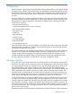
1 Overview HP XP7 Storage is a high capacity, high performance disk array that offers a wide range of storage and data services, software, logical partitioning, and simplified and unified data replication across heterogeneous disk arrays. Its large scale, enterprise class virtualization layer combined with Smart Tiers and Thin Provisioning software, delivers virtualization of internal and external storage into one pool.
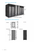
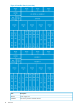
Figure 1 HP XP7 disk array (6 rack) Figure 2 XP7 disk controller rack dimensions 6 Overview
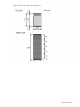
Figure 3 HP XP7 disk drive rack dimensions Hardware overview 7
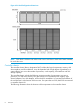
Figure 4 Six Rack Configuration dimensions NOTE: Each Rack is 600mm wide without side covers. Add 5mm to each end of entire assembly for each side cover. Controller chassis The controller chassis (factory designation DKC) includes the logical components, memory, disk drive interfaces, and host interfaces. It can be expanded with a high degree of granularity to a system offering up to twice the number of processors, cache capacity, host interfaces and disk storage capacity.
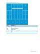
Figure 5 Controller chassis (front view) Item Description DKCPANEL Disk control panel BKM Cache Backup Module Kit MPB Processor Blade CACHE Cache DKCFAN Fan unit Hardware overview 9
Figure 6 Controller chassis (rear view) 10 Item Description DKCPS power supply unit SSVPMN sub service processor and DKC monitor Overview
Item Description MODCON Module connector unit DKCFAN Fan unit DKC disk controller CHA channel adapter MPB multiprocessor board Drive chassis The drive chassis (factory designation DKU) consists of SAS switches, slots for 2 1/2 inch, 3 1/2 inch HDD or SSD drives, and four fan door assemblies that can be easily opened to allow access to the drives. Each drive chassis can hold 128 2 1/2 inch HDD or SSD drives. The maximum number of 2 1/2 inch drives in a HP XP7 system is 2304.
Specifications The following tables provide general specifications of the HP XP7. Table 1 HP XP7 specifications Item Size Single Module Dual Module Maximum raw drive capacity (based on 1.2 TB HDDs) Internal 1229 TB 2458 TB External 247 PB 247 PB Maximum number of volumes - 64k 64k Supported drives See Table 2 (page 13). Min 64 GB Min 128 GB Max 512 GB Max 1024 GB Cache memory capacity Cache flash memory capacity Min 32 GB Max 2048 GB RAID Level .
Table 1 HP XP7 specifications (continued) Item Size Single Module Dual Module Back-end Path SAS 6G 32 (2WL*6) 64 (2WL*32) Number of ports per installation unit FC 2/4/8G 80 /16,8 160/16,8 Device I/F Controller chassis SAS/Dual Port drive chassis Interface Data transfer rate Max. 6 GBps Maximum number 256 (2.
Table 2 Drive specifications (continued) Drive Type Size Drive Capacity Speed (RPM) 2. Recommended maximum number. The drives must be added four at a time to create RAID groups, unless they are spare drives.
2 Planning the Installation The GUI illustrations in this guide were created using a Windows computer with the Internet Explorer browser. Actual windows may differ depending on the operating system and browser used. GUI contents also vary with licensed program products, storage system models, and firmware versions. Responsibilities The responsibilities for installation planning are shared by the customer and HP support.
Location: The specific location in the data center (area or “footprint” on the floor) where HP XP7 Storage will be installed.
Installation Planning Checklist Yes No Does the data center have a raised floor? Does the location meet the requirements for service clearance and cable routing (for example, floor cutouts)? Does the location meet the floor load rating requirements? Power Requirements Does the data center meet the AC input power requirements? Does the data center meet the circuit breaker and plug requirements? Is the customer supplied hardware such as connectors, receptacles, and cables ready for the installation? Enviro
• Cabling: Do not block walkways when routing cables. Do not place heavy materials on cables. Do not place cables near any possible source of heat • Warning and safety labels: Safety warnings, cautions, and instructions in various languages are attached to HP XP7 Storage components. The safety warnings provide guidelines to follow when working with any equipment. HP recommends that you read all warning labels on the hardware.
Electrical safety guidelines Even though customers do not install or maintain equipment, these guidelines are provided to prevent possible injury when working with authorized service personnel in the area where equipment is installed. Observe the following electrical safety guidelines: • Disconnect all power before installation, deinstallation, or moving equipment. • Ensure that the voltage and frequency of your power source match the voltage and frequency required by the system.
3 Installation requirements General site requirements The customer site must accommodate the delivery and movement of the equipment from the receiving dock to the installation location in the data center. Equipment clearances Receiving area: The receiving dock, storage area, and receiving area must be large enough to allow movement of and access to crated or packed equipment. The dimensions of a shipping crate for a single rack are shown in the following table.
protect the floor as the equipment is moved from the receiving area to the installation location. Consult the system bill of materials to establish the anticipated summary weights. The weight of the equipment depends on the disk array configuration.
Table 7 Data communication requirements (continued) Column Head Column Head representative will configure C-Track, contact your HP representative. A twisted pair (Cat 5) cable. Needed to connect the HP system to an available Ethernet port on the customer's LAN. To ensure network security, consult with an HP representative and your network administrator before selecting the appropriate location of your LAN drop. A public voice phone line near the disk array.
NOTE: For safe and efficient maintenance operations, clearance (c) should be made as large as possible. Actual clearances for installation should be determined after consulting with the site/facilities manager, as the clearances can vary, depending on building conditions. Although all disk chassis come pre-installed, up to 1420 mm of clearance may be required at both front and back for a disk chassis replacement. The figures in this section are not drawn to scale.
*4 Dimensions in parentheses show allowable range of the front cutout dimensions. Basically, position the floor cutout in the center of the rack. However, the position may be off center as long as the cutout allows smooth entrance of an external cable (check the relation between the positions of the cutout and the opening on the bottom plate of the rack) and is within the allowable range.
Figure 8 Service clearances for a two rack system (single DKC) *1 Clearance (a+b) is based on the floor load rating and the clearance (c). Floor load rating and required clearances are shown in Table 10 (page 25). *2 Clearance (d) is required over 300mm to open the front door. In the case that the clearance (d) is less tan the clearance (a), give priority to clearance (a).
Table 10 Floor load rating and required clearances for two rack configuration (continued) Floor Load Required Clearance (a+b) m Rating (kg/m2) 300 Clearance (c) m C=-0.3 C=0 C=0.2 C=0.4 C=0.6 C=0.8 C=1.0 C=1.4 2.2 1.8 1.6 1.4 1.3 1.1 1.0 0.8 Notes: 1. Actual clearances for installation should be determined after consulting with construction specialist responsible for installation building, as they could vary depending on the size/layout of the system and building conditions. 2.
*2 Clearance (d) is required over 300mm to open the front door. In the case that the clearance (d) is less tan the clearance (a), give priority to clearance (a). *3 Clearance (e) is required over 200mm to open the rear door. If clearance (e) is less than clearance (b), give priority to clearance (b). Table 11 Floor load rating and required clearances for a two rack configuration (two DKC) Floor Load Required Clearance (a+b) m Rating (kg/m2) Clearance (c) m C=-0.3 C=0 C=0.2 C=0.4 C=0.6 C=0.8 C=1.
Figure 10 Service clearances for a three rack system (left module) *1 Clearance (a+b) is based on the floor load rating and the clearance (c). Floor load rating and required clearances are shown in Table 12 (page 28). *2 Clearance (d) is required over 300mm to open the front door. In the case that the clearance (d) is less tan the clearance (a), give priority to clearance (a).
Table 12 Floor load rating and required clearances for a three rack configuration (left module) (continued) Floor Load Required Clearance (a+b) m Rating (kg/m2) Clearance (c) m C=-0.3 C=0 C=0.2 C=0.4 C=0.6 C=0.8 C=1.0 C=1.4 1. Actual clearances for installation should be determined after consulting with construction specialist responsible for installation building, as they could vary depending on the size/layout of the system and building conditions. 2.
*3 Clearance (e) is required over 200mm to open the rear door. If clearance (e) is less than clearance (b), give priority to clearance (b). Table 13 Floor load rating and required clearances for a three rack configuration (right module) Floor Load Required Clearance (a+b) m Rating (kg/m2) Clearance (c) m C=-0.3 C=0 C=0.2 C=0.4 C=0.6 C=0.8 C=1.0 C=1.4 Over 700 0 0 0 0 0 0 0 0 600 0.2 0 0 0 0 0 0 0 500 0.7 0.4 0.2 0.1 0 0 0 0 450 1.1 0.7 0.5 0.4 0.2 0.1 0 0 400 1.
Figure 12 Service clearances for a four rack system (left module) *1 Clearance (a+b) is based on the floor load rating and the clearance (c). Floor load rating and required clearances are shown in Table 14 (page 31). *2 Clearance (d) is required over 300mm to open the front door. In the case that the clearance (d) is less tan the clearance (a), give priority to clearance (a).
Table 14 Floor load rating and required clearances for a four rack configuration (left module) (continued) Floor Load Required Clearance (a+b) m Rating (kg/m2) Clearance (c) m C=-0.3 C=0 C=0.2 C=0.4 C=0.6 C=0.8 C=1.0 C=1.4 1. Actual clearances for installation should be determined after consulting with construction specialist responsible for installation building, as they could vary depending on the size/layout of the system and building conditions. 2.
*3 Clearance (e) is required over 200mm to open the rear door. If clearance (e) is less than clearance (b), give priority to clearance (b). Table 15 Floor load rating and required clearances for a four rack configuration (right module) Floor Load Required Clearance (a+b) m Rating (kg/m2) Clearance (c) m C=-0.3 C=0 C=0.2 C=0.4 C=0.6 C=0.8 C=1.0 C=1.4 Over 700 0 0 0 0 0 0 0 0 600 0.1 0 0 0 0 0 0 0 500 0.8 0.4 0.2 0 0 0 0 0 450 1.3 0.8 0.6 0.4 0.2 0.1 0 0 400 1.
Figure 14 Service clearances for a five rack system *1 Clearance (a+b) is based on the floor load rating and the clearance (c). Floor load rating and required clearances are shown in Table 16 (page 34). *2 Clearance (d) is required over 300mm to open the front door. In the case that the clearance (d) is less tan the clearance (a), give priority to clearance (a).
Table 16 Floor load rating and required clearances for a five rack configuration (continued) Floor Load Required Clearance (a+b) m Rating (kg/m2) 300 Clearance (c) m C=-0.3 C=0 C=0.2 C=0.4 C=0.6 C=0.8 C=1.0 C=1.4 5.2 4.2 3.7 3.2 2.8 2.5 2.2 1.6 Notes: 1. Actual clearances for installation should be determined after consulting with construction specialist responsible for installation building, as they could vary depending on the size/layout of the system and building conditions. 2.
*1 Clearance (a+b) is based on the floor load rating and the clearance (c). Floor load rating and required clearances are shown in Table 17 (page 36). *2 Clearance (d) is required over 300mm to open the front door. In the case that the clearance (d) is less tan the clearance (a), give priority to clearance (a). Table 17 Floor load rating and required clearances for a six rack configuration Floor Load Required Clearance (a+b) m Rating (kg/m2) Clearance (c) m C=-0.3 C=0 C=0.2 C=0.4 C=0.6 C=0.8 C=1.
4 Power On/Off procedures Safety and environmental information CAUTION: Before operating or working on the HP XP7 disk array, read the safety section in the HP XP7 Site Preparation Guide. Standby mode When the disk array power cables are plugged into the PDUs and the PDU breakers are ON, the disk array is in standby mode. When the disk array is in standby mode: • The Basic Supply (BS) LED on the control panel is ON. This indicates that power is applied to the power supplies. • The READY LED is OFF.
Follow this procedure exactly when powering the disk array on. Refer to the illustration of the control panel as needed. 1. On the control panel, check the amber BS LED and make sure it is lit. It indicates that the disk array is in standby mode. 2. In the PS area on the control panel, move the Enable switch to the ENABLED position. Hold the switch in the Enabled position and move the PS ON switch to the ON position. Then release the ENABLE switch. 3.
2. Wait for the disk array to complete its shutdown routines. Depending on the disk array configuration and certain MODE settings, it can take up to 20 minutes for the disk array to copy data from cache to the disk drives and for the disk drives to spin down. NOTE: If the Ready and PS LEDs do not turn OFF after 20 minutes, contact HP Technical Support. Battery backup operations The HP XP7 is designed so that it cannot lose data or configuration information if the power fails.
Battery life The batteries have a lifespan of three years, and will hold the charge when connected. When the batteries are connected and power is on, they are charged continuously. This occurs during both normal system operation and while the system is in standby mode. When the batteries are connected and the power is off, the batteries slowly discharge. They will have a charge of less than 50% after two weeks without power.
5 System specifications and requirements This section describes the physical characteristics of a HP XP7 disk array, including • “Mechanical specifications” (page 42) • “Electrical specifications” (page 42) • “Environmental specifications” (page 46) General system specifications Capacity: • 4.5PB Raw • 3.
Dimensions and weight: • Minimum dimensions (W x D x H): 24.1 x 43.8 x 79.0 in - per rack • Weight: 1775 lbs - Based on a single DKC rack with 384 SFF HDDs Mechanical specifications The following table lists the mechanical specifications of the HP XP7 disk array. Table 19 HP XP7 mechanical specifications Dimension One Rack Two Racks Three Racks Four Racks Five Racks Six Racks Width 24.0 inches 47.6 inches 71.3 inches 95 inches 118.
Table 21 System components heat and power specifications Component Product Number HP XP7 Disk Array Component Power Consumption Heat Output (kW)1 (kVA)1 H6F62A Flash Module Chassis 0.6004 0.6404 H6G70A, H6G71A Flash Module 0.0173 0.0183 H6F56A Disk Array DKC Module-0 Rack 1.88 1.97 H6F57A DKC Module-1 Rack 1.83 1.93 H6F62A Flash Module Chassis 0.6004 0.6404 H6G70A 1.6TB Flash Module 0.0173 0.0183 H6G71A 3.2TB Flash Module 0.0183 0.0193 H6F56A Disk Array DKC Module-0 Rack 1.
Table 21 System components heat and power specifications (continued) Power Consumption Heat Output (kW)1 (kVA)1 Component Product Number HP XP7 Disk Array Component 2 Power is consumed during the battery back-up time only. 3 Actual values at a typical I/O condition. (Random Read and Write, 50 IOPSs for HDD, 2500 IOPSs for SSD, Data Length: 8 KB). These values may increase for future compatible drives. 4 Maximum values with all fans rotate at maximum.
Table 22 HP XP7 AC PDU Options (continued) Product Number Local Power Branch circuit Number of requirements PDU per Rack1 per PDU Plug Type Facility receptacle needed Notes Distribution System H6F73A 3 phase (5 wire) 2 380-415V, 3Ø, 5-wire, 16A IEC60309 4 pole, 5-wire 380-415VAC, 16A IEC60309 4 pole, 5-wire, 380-415 VAC, 16A For customers with 380 - 415 VAC, Three-Phase, 5-Wire Wye Power Distribution System H6F70A single phase NEMA 4 200-240V, 1Ø, NEMA L6-30P NEMA L6-30R For customers 3-wire
Figure 17 Direct Power Connection Figure 18 Power Connection via UPS Environmental specifications Table 24 (page 47)provides the environmental specifications and requirements for the HP XP7 disk array.
Table 24 HP XP7 Environmental specifications Item Operating Not Operating In Storage Temperature ºC 60.8 - 80.9 / -10 to 43 -25 to 60 16 to 32 -10 to 358 Relative Humidity (%)2 20 to 80 8 to 90 5 to 95 Max. Wet Bulb ºC 26 27 29 Temperature Deviation ºC 10 per hour) 10 20 Vibration to 10Hz: 0.25 mm 5 to 10Hz: 0.25 mm 5 to 10 Hz: 2.5 mm 10 to 300Hz: 10 to 70 Hz: 4.9 m/s1 0.49m/s2 70 to 99 Hz: 0.05 mm 99 to 300 Hz: 9.8 m/s1 Sine Vibration: 4.9 m/s1, 5 min.
Table 25 Heat, power, and airflow Model Number Heat Output (kW) Power Consumption (kVA) Air Flow (M3/min) H6F62A HP XP7 Flash Module Chassis 0.6006 0.6406 - H6G70A HP XP7 1.6TB Flash 0.0173 Module 0.0183 - H6G71A HP XP7 3.2TB Flash 0.0183 Module 0.0193 - H6F56A - HP XP7 Disk Array 1.881 DKC Module-0 Rack 1.971 25 H6F57A - HP XP7 DKC Module-1 Rack 1.831 1.931 25 H6F60A HP XP7 Base 2.5in Drive Chassis see note 5 see note 5 - 0.57 0.600 - H6F60A Complete 2.
Table 25 Heat, power, and airflow (continued) Model Number Heat Output (kW) 3 H6G43A - HP XP7 1.2TB SAS 0.0082 7.2K 2.5in DP HDD 3 H6G40A - HP XP7 300GB SAS 10K 2.5in DP HDD 0.0063 H6G41A - HP XP7 600GB SAS 10K 2.5in DP HDD 0.0080 3 3 H6G43A - HP XP7 1.2TB 6G 0.0083 SAS 10K 2.5in DP HDD 3 Power Consumption (kVA) 3 0.0087 3 0.0067 3 0.0085 3 0.0087 3 H6G40A - HP XP7 300GB SAS 15K 2.5in DP HDD 0.0086 0.0090 H6G42A - HP XP7 900GB SAS 15K 2.5in DP HDD 0.00902 0.
HP XP7 disk arrays use the following values to calculate logical storage capacity values (logical devices): 50 • 1 KB (kilobyte) = 1,024 bytes • 1 MB (megabyte) = 1,0242 bytes • 1 GB (gigabyte) = 1,0243 bytes • 1 TB (terabyte) = 1,0244 bytes • 1 PB (petabyte) = 1,0245 bytes • 1 EB (exabyte) = 1,0246 bytes System specifications and requirements
6 Support and other resources Contacting HP For worldwide technical support information, see the HP Support Center: http://www.hp.com/go/hpsc Before contacting HP, collect the following information: • Product model names and numbers • Technical support registration number (if applicable) • Product serial numbers • Error messages • Operating system type and revision level • Detailed questions Documentation feedback HP welcomes your feedback.
• http://www.hp.com/support/downloads • http://www.hp.
A Regulatory information For important safety, environmental, and regulatory information, see Safety and Compliance Information for Server, Storage, Power, Networking, and Rack Products, available at http:// www.hp.com/support/Safety-Compliance-EnterpriseProducts. Belarus Kazakhstan Russia marking Manufacturer and Local Representative Information Manufacturer’s information: • Hewlett-Packard Company, 3000 Hanover Street, Palo Alto, California 94304, U.S.
HP Enterprise Servers http://www.hp.com/support/EnterpriseServers-Warranties HP Storage Products http://www.hp.com/support/Storage-Warranties HP Networking Products http://www.hp.