
HP XP7 Getting Started Guide
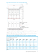
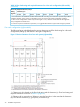
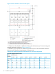
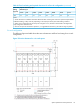
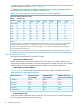
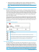
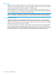

Table 14 Floor load rating and required clearances for a four rack configuration (left module)
(continued)
Required Clearance (a+b) m
Clearance (c) m
Floor Load
Rating
(kg/m2)
C=1.4C=1.0C=0.8C=0.6C=0.4C=0.2C=0C=-0.3
1. Actual clearances for installation should be determined after consulting with construction specialist responsible for
installation building, as they could vary depending on the size/layout of the system and building conditions.
2. When various configurations of disk arrays are arranged in a row, clearance values based on the largest disk
array configuration should be used.
3. From the viewpoint of maintenance operations, it is suggested that Clearance (c) be made as large as possible.
Four rack configuration (right module)
The following figure and table shows the service clearances and floor load rating for a four-rack
configuration (Setting Up DKC-RACK in the right Configuration).
Figure 13 Service clearances for a four rack system (right module)
*1 Clearance (a+b) is based on the floor load rating and the clearance (c). Floor load rating and
required clearances are shown in Table 15 (page 33).
*2 Clearance (d) is required over 300mm to open the front door. In the case that the clearance
(d) is less tan the clearance (a), give priority to clearance (a).
32 Installation requirements