XP7 RAID Manager Installation and Configuration User Guide Abstract This document describes and provides instructions for installing the RAID Manager (RAID Manager) software for the Hitachi RAID storage systems, including upgrading and removing RAID Manager. The Hitachi RAID storage systems include the HP XP7Storage, P9500, XP24000/XP20000 Disk Array, XP12000 Disk Array, and XP10000 Disk Array.
© Copyright 2014 Hewlett-Packard Development Company, L.P. Confidential computer software. Valid license from HP required for possession, use or copying. Consistent with FAR 12.211 and 12.212, Commercial Computer Software, Computer Software Documentation, and Technical Data for Commercial Items are licensed to the U.S. Government under vendor's standard commercial license. The information contained herein is subject to change without notice.
Contents 1 Installation requirements..............................................................................5 System requirements..................................................................................................................5 Supported environments............................................................................................................7 Supported Business Copy environments...................................................................................
5 Troubleshooting........................................................................................48 Troubleshooting......................................................................................................................48 6 Support and other resources......................................................................49 Contacting HP........................................................................................................................49 Subscription service.........
1 Installation requirements This chapter describes the installation requirements for the RAID Manager (RAID Manager) software. System requirements RAID Manager operations involve the RAID Manager software on the UNIX/PC server host, the command device(s) on the RAID storage system(s), and the logical volumes on the RAID storage system(s). The system requirements for RAID Manager are: • RAID Manager software product. The RAID Manager software is supplied on CD-ROM.
the description of the configuration file.It is necessity (Number of units ID×200 KB + Number of LDEV×360B + Number of the entry×180B) in the minimum ◦ Unit ID: the number of the storage chassis ◦ Number of LDEV: the number of the LDEVs (each instance) ◦ Number of entry: the number of the paired entries Example:If 1:3 pair configuration, the primary instance becomes the number of the LDEVs =1 and the number of the entries (the number of the pairs) = 3.
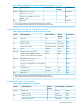
Supported environments This section specifies the supported operating systems, failover software, and I/O interfaces for data management operations using RAID Manager. For the latest information about host software support for RAID Manager, please contact your HP account team. Supported Business Copy environments Table 1 Supported Platforms for Business Copy Vendor Operating System Failover Software Volume Manager I/O Interface Oracle Solaris 2.
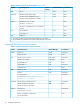
Table 2 Supported Platforms for Continuous Access Synchronous (continued) Vendor IBM Operating System Failover Software Volume Manager I/O Interface OpenVMS 7.3-1 – – Fibre DYNIX/ptx 4.4 ptx/Cluster SVM SCSI/Fibre AIX 4.3 HACMP LVM SCSI/Fibre z/Linux (Suse 8) – – Fibre (FCP) Windows NT 4.0, Windows 2000, 2003, 2008 MSCS LDM Fibre Windows 2003/2008(R2) on IA641 MSCS LDM Fibre – – SCSI/Fibre2 AS/ES 2.1, 3.0 Update2, 4.0, 5.0 on EM64T / IA641 – – Fibre IRIX64 6.
Table 3 Supported Platforms for Continuous Access Asynchronous (continued) Vendor Operating System Failover Software Volume Manager I/O Interface Red Hat Red Hat Linux 6.0, 7.0, 8.0 – – SCSI/Fibre2 AS/ES 2.1, 3.0 Update2, 4.0, 5.0 on EM64T / IA641 – – Fibre IRIX64 6.5 – – SCSI/Fibre AS/ES 2.1, 3.0, 4.0, 5.0 SGI 1. IA64: using IA-32EL on IA64 (except RAID Manager for Linux/IA64) 2. See Troubleshooting described in the HP XP7 RAID Manager User Guide.
Table 5 Supported Platforms for Snapshot (continued) Vendor Operating System Failover Software Volume Manager I/O Interface IBM AIX 5.1 – LVM Fibre Microsoft Windows 2000, 2003, 2008 – LDM Fibre – LDM Fibre – – Fibre2 AS/ES 2.1, 3.0 Update2, 4.0, 5.0 on EM64T / IA641 – – Fibre2 Tru64 UNIX 5.0 – LSM Fibre OpenVMS 7.3-1 – – Fibre IRIX64 6.5 – – Fibre 1 Windows 2003/2008(R2) on IA64 Windows 2003/2008/2012 on EM64T Red Hat Red Hat Linux 6.0, 7.0, 8.0 AS/ES 2.1, 3.0, 4.
Table 6 Supported Platforms for Data Retention (continued) Vendor Operating System Volume Manager I/O Interface SGI IRIX64 6.5 – SCSI/Fibre 1. IA64: using IA-32EL on IA64 (except RAID Manager for Linux/IA64) 2. See Troubleshooting described in the HP XP7 RAID Manager User Guide. Supported Database Validator environments Table 7 Supported Platforms for Database Validator Vendor Operating System Volume Manager I/O Interface Oracle Solaris 2.
Table 8 Supported Guest OS for VM (continued) VM Vendor Layer Guest OS RAID Manager Support Confirmation Volume Mapping I/O Interface Solaris 10 u3 (x86) Confirmed RDM1 Fibre SVC Linux Kernel 2.4.9 Confirmed Direct Fibre IBM AIX 5.3 VIO Server 3 Client AIX 5.3 Confirmed Physical mode Fibre Server AIX 5.
Table 10 Supported Platforms: IPv4 vs IPv6 (continued) IPv4 RAID Manager / IPv6* Linux AV AV AV N/A AV AV N/A Tru64 AV AV AV N/A AV AV N/A OpenVMS AV AV AV N/A AV AV AV IRIX64 AV AV AV N/A AV AV N/A *See “About platforms supporting IPv6” (page 18). Legend: AV: Available for communicating with different platforms. N/A: Not applicable (Windows LH does not support IPv4 mapped IPv6). Minimum platform versions for RAID Manager/IPv6 support: • HP-UX: HP-UX 11.
The restrictions for using RAID Manager with z/Linux are: • Command device. RAID Manager uses a SCSI Path-through driver to access the command device. As such, the command device must be connected through FCP adaptors. • Open Volumes via FCP. You can control the Business Copy and Continuous Access Synchronous pair operations without any restrictions. • Mainframe (3390-9A) Volumes via FICON. You cannot control the volumes (3390-9A) that are directly connected to FICON for Business Copy pair operations.
Figure 2 RAID Manager Configuration on Guest OS/VMware The restrictions for using RAID Manager with VMware are: 1. Guest OS. RAID Manager needs to use guest OS that is supported by RAID Manager, and also VMware supported guest OS (for example, Windows Server 2003, Red Hat Linux,SuSE Linux). See “Supported guest OS for VM” (page 11). 2. Command device. RAID Manager uses SCSI path-through driver to access the command device.
Figure 3 RAID Manager Configuration on VIO Client The restrictions for using RAID Manager on AIX VIO are: 1. Command device. RAID Manager uses the SCSI Path-through driver for accessing the command device. Therefore, the command device must be mapped as RAW device of Physical Mapping Mode. At least one command device must be assigned for each VIO Client.
4. About running on VIO Server. The volume mapping ( /dev/rhdisk) on a VIO Server is a physical connection without converting SCSI Inquiry, so RAID Manager will perform as if running on AIX 5.3. However, IBM does not allow running applications in the VIO server. Since commands or scripts would have to be run outside the restricted shell, it may be necessary to get IBM approval to run in the VIO server.
About platforms supporting IPv6 Library and system call for IPv6 RAID Manager uses the following functions of IPv6 library to get and convert from hostname to IPv6 address.
export IPV6_DLLPATH=/usr/lib/hpux32/lib.so horcmstart.sh 10 • $IPV6_GET_ADDR: This variable is used to change "AI_PASSIVE" value as default for specifying to the getaddrinfo() function for IPv6. For example: export IPV6_GET_ADDR=9 horcmstart.sh 10 HORCM Start-Up Log Support level of IPv6 feature depends on the platform and OS version.
Therefore, if RAID Manager and HORCM are executing in different jobs (different terminal), then you must redefine LNM$TEMPORARY_MAILBOX in the LNM$PROCESS_DIRECTORY table as follows: $ DEFINE/TABLE=LNM$PROCESS_DIRECTORY LNM$TEMPORARY_MAILBOX LNM$GROUP (4) Start-up method for HORCM daemon HORCM can start as the daemon process from a UNIX Shell. But in the case of 'vfork' of CRTL, if a parent process has exit() then a child process also ends at the same time.
(5) Command device RAID Manager uses the SCSI class driver for accessing the command device on the XP1024/XP128 Disk Array, because OpenVMS does not provide the raw I/O device such as UNIX, and defines "DG*,DK*,GK*" as the logical name for the device. The SCSI class driver requires the following privileges: DIAGNOSE and PHY_IO or LOG_IO (for details see the OpenVMS manual).
The followings upper-case strings are not case sensitive: • DG* or DK* or GK* for Logical Device Name • -CLI or -FCA(-FHORC) or -FBC(-FMRCF) for the pair* command options • -CLI or -CLIWP or -CLIWN or -CM for the inqraid options • Environmental variable name such as HORCMINST … controlled by CRTL Also you need to define the following logical name to your login.
$ DEFINE DECC$ARGV_PARSE_STYLE ENABLE $ SET PROCESS/PARSE_STYLE=EXTENDED where Device:[directory] is defined as SYS$POSIX_ROOT For Installing: $ PRODUCT INSTALL RM /source=Device:[directory]/LOG _$ /destination=SYS$POSIX_ROOT:[000000] Device:[directory] where HITACHI-ARMVMS-RM-V0122-2-1.PCSI exists : : $ PRODUCT SHOW PRODUCT RM ----------------------------------------- ----------- -----------PRODUCT KIT TYPE STATE ----------------------------------------- ----------- -----------HITACHI ARMVMS RM V1.
$1$DGA149: $1$DGA151: $1$DGA152: $1$DGA153: (VMS4) (VMS4) (VMS4) (VMS4) Online Online Online Online 0 0 0 0 $ inqraid DKA145-153 -cli DEVICE_FILE PORT SERIAL LDEV CTG H/M/12 SSID R:Group PRODUCT_ID DKA145 CL1-H 30009 145 - - OPEN-9-CM DKA146 CL1-H 30009 146 - s/P/ss 0004 5:01-11 OPEN-9 DKA147 CL1-H 30009 147 - s/S/ss 0004 5:01-11 OPEN-9 DKA148 - - - DKA149 CL1-H 30009 149 - P/s/ss 0004 5:01-11 OPEN-9 DKA150 - - - DKA151 CL1-H 30009 151 - P/s/ss 0004 5:01-11 OPEN-9 DKA152 CL1-H 30009 152 - s/s/ss 0004 5:
You need to define the Path for the RAID Manager commands to DCL$PATH as the foreign command. See the section about Automatic Foreign Commands in the OpenVMS user documentation. $ DEFINE DCL$PATH SYS$POSIX_ROOT:[horcm.usr.bin],SYS$POSIX_ROOT:[horcm.
#dev_group ip_address service VG01 HOSTB horcm1 For horcm1.conf HORCM_DEV #dev_group dev_name port# TargetID VG01 oradb1 CL1-H 0 3 0 VG01 oradb2 CL1-H 0 5 0 VG01 oradb3 CL1-H 0 7 0 HORCM_INST #dev_group ip_address service VG01 HOSTA horcm0 LU# MU# Defines the UDP port name for HORCM communication in the SYS$SYSROOT:[000000.TCPIP$ETC]SERVICES.DAT file, as in the example below. horcm0 30001/udp horcm1 30002/udp (7) Start horcm0 and horcm1 as the Detached process. $ run /DETACHED SYS$SYSTEM:LOGINOUT.
$ DELETE/SYMBOL HORCC_MRCF $ pairdisplay -g VG01 -fdc Group PairVol(L/R) Device_File ,Seq#,LDEV#.P/S,Status,Fence, % ,P-LDEV# M VG01 oradb1(L) DKA146 30009 146..SMPL ---- ------,----- ---- VG01 oradb1(R) DKA147 30009 147..SMPL ---- ------,----- ---- VG01 oradb2(L) DKA148 30009 148..SMPL ---- ------,----- ---- VG01 oradb2(R) DKA149 30009 149..SMPL ---- ------,----- ---- VG01 oradb3(L) DKA150 30009 150..SMPL ---- ------,----- ---- VG01 oradb3(R) DKA151 30009 151..
HORCM_CMD #dev_name dev_name dev_name #UnitID 0 (Serial# 30009) DKA145 # ERROR [CMDDEV] DKA145 HORCM_DEV #dev_group dev_name port# # DKA146 SER = 30009 LDEV URA URA_000 CL1-H # DKA147 SER = 30009 LDEV URA URA_001 CL1-H # DKA148 SER = 30009 LDEV URA URA_002 CL1-H # DKA149 SER = 30009 LDEV URA URA_003 CL1-H # DKA150 SER = 30009 LDEV URA URA_004 CL1-H SER = 30009 LDEV = 145 [ OPEN-9-CM ` TargetID LU# MU# 146 [ FIBRE FCTBL = 2 0 147 [ FIBRE FCTBL = 3 0 148 [ FIBRE FCTBL = 4 0 149 [ FIBRE FCTBL = 5 0 150 [ FI
Group PairVol(L/R) Device_File M ,Seq#,LDEV#..P/S,Status, % ,P-LDEV# M BCVG oradb1(L) $1$DGA146 0 30009 146..P-VOL PAIR, 100 147 BCVG oradb1(R) $1$DGA147 0 30009 147..S-VOL PAIR, 100 146 $ $ pairdisplay -dg $1$DGA146 Group PairVol(L/R) (Port#,TID, LU-M) ,Seq#,LDEV#..P/S,Status, Seq#,P-LDEV# M BCVG oradb1(L) (CL1-H,0, 2-0) 30009 146..P-VOL PAIR, 30009 147 BCVG oradb1(R) (CL1-H,0, 3-0) 30009 47..
HORCM_INST #dev_group ip_address service You will have to start HORCM without a description for HORCM_DEV and HORCM_INST because target ID & Lun are Unknown. You can determine a mapping of a physical device with a logical name easily by using the raidscan -find command option. (4) Execute an 'horcmstart 0' as background. bash$ horcmstart 0 & 18 bash$ starting HORCM inst 0 (5) Verify a physical mapping of the logical device.
Using RAID Manager with Hitachi and other storage systems Table 11 (page 31) shows the related two controls between RAID Manager and the RAID storage system type (Hitachi or HP XP). Figure 6 (page 32) shows the relationship between the application, RAID Manager, and RAID storage system.
Figure 6 Relationship between application, RAID Manager, and storage system 32 Installation requirements
2 Installing and configuring RAID Manager This chapter describes and provides instructions for installing and configuring RAID Manager. Installing the RAID Manager hardware Installation of the hardware required for RAID Manager is performed by the user and the HP representative. To install the hardware required for RAID Manager operations: 1. User: 1. Make sure that the UNIX/PC server hardware and software are properly installed and configured. See “Supported environments” (page 7). 2.
to UNIX commands that may be different on your platform. Please consult your operating system documentation (for example, UNIX man pages) for platform-specific command information. To install the RAID Manager software into the root directory: 1. Insert the installation medium into the I/O device properly. 2. Move to the current root directory: # cd / 3. Copy all files from the installation medium using the cpio command: 4.
2. 3. 4. 5. Change the owner of the raw device file of the HORCM_CMD (control device) command device in the configuration definition file from the root user to the desired user name. Optional: Establishing the HORCM (/etc/horcmgr) start environment: If you have designation of the full environment variables (HORCM_LOG HORCM_LOGS), then start the horcmstart.sh command without an argument. In this case, the HORCM_LOG and HORCM_LOGS directories must be owned by the RAID Manager administrator.
3. screen to complete the installation.The install directory is HORCM (fixed value) directly under the drive. Reboot the Windows server, and verify that the correct version of the RAID Manager software is running on your system by executing the raidqry command: D:\HORCM\etc> raidqry -h Model: P9000 Raid-Manager-XP/WindowsNT Ver&Rev: 01.30.xx Usage: raidqry [options] for HORC A warning message for security may appear at the initial start-up depending on the OS settings.
RAID Manager Administrator Tasks 1. Establish the HORCM (/etc/horcmgr) startup environment. By default, copy the configuration definition file in the following directory: %SystemDrive%:\windows\ Because users cannot write to this directory, the RAID Manager administrator must change the directory by using the HORCM_CONF variable. For example: C:\HORCM\etc\>set HORCM_CONF=C:\Documents and Settings\RMadmin\horcm10.
2. Execute the following command: $ PRODUCT INSTALL RM /source=Device:[PROGRAM.RM.OVMS]/LOG _$ /destination=SYS$POSIX_ROOT:[000000] Device:[PROGRAM.RM.OVMS] where HITACH-ARMVMS-RM-V0122-2-1.PCSI exists 3. Verify installation of the proper version using the raidqry command: $ raidqry -h Model: RAID-Manager/OpenVMS Ver&Rev: 01-22-03/06 Usage: raidqry [options] 4. Follow the requirements and restrictions in “Porting notice for OpenVMS” (page 19).
Figure 7 System Configuration Example and Setting Example of Command Device and Virtual Command Device by In-Band and Out-of-Band Methods Setting up UDP ports This section contains information that may be of assistance in setting up strict firewalls. If you do not have a HORCM_MON IP address in your configuration definition file, RAID Manager (horcm) opens the following ports on horcmstart.
volume space is reserved for RAID Manager and its utilities. A Virtual LUN volume as small as 36 MB can be used as a command device. First you set the command device using LUN Manager, and then you define the command device in the HORCM_CMD section of the configuration definition file for the RAID Manager instance on the attached host. When you use a command for provisioning, user authentication is required. Set enable the user authentication on the security attribute of a command device.
By creating the virtual command device, transfer the command from the client or the server via LAN to the virtual command device of the set IP address in the SVP, and assign an operation instruction to the storage system. A setting example of a command device and a virtual command device (by the in-band and out-of-band methods) in a configuration definition file is shown below. For details, see the manual HP XP7 RAID Manager User Guide.
Figure 8 Alternate Command Device Function Creating/editing the configuration definition file The configuration definition file is a text file that is created and edited using any standard text editor (for example, UNIX vi editor, Windows Notepad). The configuration definition file defines correspondences between the server and the volumes used by the server. There is a configuration definition file for each host server.
Table 12 Configuration (HORCM_CONF) parameters (continued) Parameter Default Type Limit dev_name for HORCM_DEV None Character string 31 characters dev_group None Character string 31 characters Recommended value = 8 char.
3 Upgrading RAID Manager For upgrading the RAID Manager software, the RMuninst scripts on the CD-ROM are used. For other media, please use the instructions in this chapter to upgrade the RAID Manager software. The instructions may be different on your platform. Please consult your operating system documentation (for example, UNIX man pages) for platform-specific command information.
7. 8. screen to complete the installation. The install directory is HORCM (fixed value) directly under the drive. An InstallShield opens. Follow the instructions on the screen to install the RAID Manager software. Reboot the Windows server, and verify that the correct version of the RAID Manager software is running on your system by executing the raidqry -h command. Example: C:\HORCM\etc>raidqry -h Model : P9000 Raid-Manager-XP/WindowsNT Ver&Rev: 01.30.xx Usage : raidqry [options] for HORC 9.
4 Removing RAID Manager This chapter describes and provides instructions for removing the RAID Manager software. Removing RAID Manager in a UNIX environment To remove the RAID Manager software: 1. If you are discontinuing local and/or remote copy functions (for example, Business Copy, Continuous Access Synchronous), delete all volume pairs and wait until the volumes are in simplex status. If you will continue copy operations using Remote Web Console, do not delete any volume pairs. 2.
2. You can remove the RAID Manager software only when RAID Manager is not running. If RAID Manager software is running, shut down RAID Manager using the horcmshutdown command to ensure a normal end to all functions: One RAID Manager instance: D:\HORCM\etc> horcmshutdown Two RAID Manager instances: D:\HORCM\etc> horcmshutdown 0 1 3. Delete the RAID Manager software using the Add or Remove Programs control panel: 1. Open the Control Panel, and double-click Add or Remove Programs. 2.
5 Troubleshooting This chapter provides troubleshooting information for RAID Manager. Troubleshooting If you have a problem installing or upgrading the RAID Manager software, make sure that all system requirements and restrictions have been met. If you need to call the HP Technical Support, please provide as much information about the problem as possible, including: • The circumstances surrounding the error or failure. • The exact content of any error messages displayed on the host system(s).
6 Support and other resources Contacting HP For worldwide technical support information, see the HP support website: http://www.hp.
HP websites For additional information, see the following HP websites: • http://www.hp.com • http://www.hp.com/go/storage • http://www.hp.com/service_locator • http://www.hp.com/support/manuals • http://www.hp.com/support/downloads • http://www.hp.
Table 13 Document conventions (continued) Convention Element Monospace text • File and directory names • System output • Code • Commands, their arguments, and argument values Monospace, italic text • Code variables • Command variables Monospace, bold text WARNING! CAUTION: IMPORTANT: NOTE: TIP: Emphasized monospace text Indicates that failure to follow directions could result in bodily harm or death. Indicates that failure to follow directions could result in damage to equipment or data.
A Fibre-to-SCSI address conversion Disks connected with fibre channel display as SCSI disks on UNIX hosts. Disks connected with fibre channel connections can be fully utilized. RAID Manager converts fibre-channel physical addresses to SCSI target IDs (TIDs) using a conversion table (see Figure 9 (page 52)). Table 14 (page 52) shows the current limits for SCSI TIDs and LUNs on various operating systems.
Example 6 Using Raidscan to Display TID and LUN for Fibre-Channel Devices C:\>raidscan -pd hd6 -x drivescan hd6 Harddisk 6... Port[ 2] PhId[ 4] TId[ 3] Lun[ 5] [HITACHI ] [OPEN-3 ] Port[CL1-J] Ser#[ 30053] LDEV#[ 14(0x00E)] HORC = SMPL HOMRCF[MU#0 = SMPL MU#1 = SMPL MU#2 = SMPL] RAID5[Group 1- 2] SSID = 0x0004 PORT# /ALPA/C,TID#,LU#.Num(LDEV#....)...P/S, Status,Fence,LDEV#,P-Seq#,P-LDEV# CL1-J / e2/4, 29, 0.1(9).............SMPL ---- ------ ----, ----- ---CL1-J / e2/4, 29, 1.1(10)............
Figure 10 LUN Configuration RAID Manager uses absolute LUNs to scan a port, whereas the LUNs on a group are mapped for the host system so that the target ID & LUN, which is indicated by the raidscan command, is different from the target ID & LUN shown by the host system. In this case, the target ID & LUN indicated by the raidscan command should be used. In this case, you must start HORCM without a description for HORCM_DEV and HORCM_INST because target ID & LUN are unknown.
Fibre address conversion tables Table 15 (page 55), Table 16 (page 55), Table 17 (page 56) and show the fibre address conversion tables: • Table number 0 = HP-UX systems (see Table 15 (page 55)) • Table number 1 = Solaris and IRIX systems (see Table 16 (page 55)) • Table number 2 = Windows systems (see Table 17 (page 56)) The conversion table for Windows systems is based on the Emulex driver.
Table 16 Fibre Address Conversion Table for Solaris and IRIX Systems (Table1) (continued) C0 C1 C2 C3 C4 C5 C6 C7 AL-PA TID AL-PA TID AL-PA TID AL-PA TID AL-PA TID AL-PA TID AL-PA TID AL-PA TID E2 3 CA 19 AD 35 8F 51 6D 67 52 83 35 99 1E 115 E1 4 C9 20 AC 36 88 52 6C 68 51 84 34 100 1D 116 E0 5 C7 21 AB 37 84 53 6B 69 4E 85 33 101 1B 117 DC 6 C6 22 AA 38 82 54 6A 70 4D 86 32 101 18 118 DA 7 C5 23 A9 39 81 55 69 71
B Sample configuration definition files This chapter describes sample configuration definition files for typical RAID Manager configurations. Sample configuration definition files Figure 11 (page 57) illustrates the configuration definition of paired volumes. Example 9 “Configuration File Example – UNIX-Based Servers” shows a sample configuration file for a UNIX-based operating system. Figure 12 (page 58) shows a sample configuration file for a Windows operating system.
Example 9 Configuration File Example – UNIX-Based Servers HORCM_MON #ip_address service poll(10ms) timeout(10ms) HST1 horcm 1000 3000 HORCM_CMD #unitID 0... (seq#30014) #dev_name dev_name dev_name /dev/rdsk/c0t0d0 #unitID 1...
• Poll: Specifies the interval for monitoring paired volumes in increments of 10 ms. To reduce the HORCM daemon load, make this interval longer. If set to -1, the paired volumes are not monitored. The value of -1 is specified when two or more RAID Manager instances run on a single machine. • Timeout: The time-out period of communication with the remote server. If HORCM_MON will not be specified, then sets the following as defaults.
following naming format specifying Serial#/LDEV#/Port# as notation of the command device for only Windows. For XP7 Storage, set the number to which 300,000 is added to the serial number. \\.\CMD-Ser#-ldev#-Port# HORCM_CMD #dev_name dev_name \\.\CMD-30095-250-CL1-A dev_name To allow more flexibility, RAID Manager allows the following format. • For minimum specification. Specifies to use any command device for Serial#30095 \\.
If a HINT is already specified, ":HINT" can be omitted for next command devices, and then a command device is found from the cached Inquiry information of HORCM for saving unnecessary device scanning. HORCM_CMD #dev_name dev_name dev_name \\.\CMD-30095-250-CL1:/dev/rdsk/ \\.\CMD-30095-250-CL2 Example for minimum specification. Specifies to use any command device for Serial#30095: \\.\CMD-30095:/dev/rdsk/ Example for under Multi Path Driver.
For XP1024/XP128 Disk Array, RAID Manager supports four types of port names for host groups: • Specifying the port name without a host group: CL1-A CL1-An where n unit ID for multiple RAID • Specifying the port without a host group: CL1-A-g where g : host group CL1-An-g where n-g : host group=g on CL1-A in unit ID=n The following ports can only be specified for XP12000 Disk Array/XP10000 Disk Array and XP24000/XP20000 Disk Array: Port Basic CL5 an bn cn dn en fn gn hn jn kn ln mn nn pn
• MU# for Continuous Access Synchronous/Continuous Access Journal: Defines the mirror unit number (0 - 3) if using redundant mirror for the identical LU on Continuous Access Synchronous/Continuous Access Journal. If this number is omitted, it is assumed to be zero (0). The Continuous Access Journal mirror description is described in the MU# column by adding "h" to identify identical LUs as the mirror descriptor for Cnt Ac-J. The MU# for Continuous Access Synchronous can be specified "0" only.
Figure 14 Configuration for Multiple Networks For example: # horcctl -ND -g IP46G Current network address = 158.214.135.106,services = 50060# horcctl -NC -g IP46G Changed network address(158.214.135.106,50060 -> fe80::39e7:7667:9897:2142,50060) For IPv6 only, the configuration must be defined as HORCM/IPv6. Figure 15 Network Configuration for IPv6 It is possible to communicate between HORCM/IPv4 and HORCM/IPv6 using IPv4 mapped to IPv6.
Figure 16 Network Configuration for IPv4 Mapped IPv6 In the case of mixed IPv4 and IPv6, it is possible to communicate between HORCM/IPv4 and HORCM/IPv6 and HORCM/IPv6 using IPv4 mapped to IPv6 and native IPv6.
(5) HORCM_LDEV The HORCM_LDEV parameter is used for specifying stable LDEV# and Serial# as the physical volumes corresponding to the paired logical volume names. Each group name is unique and typically has a name fitting its use (for example, database data, Redo log file, UNIX file). The group and paired logical volume names described in this item must also be known to the remote server. • dev_group: This parameter is the same as HORCM_DEV parameter.
Array. The same path ID must be specified between the site of P-VOL and S-VOL because the path ID is used at the paircreate command. (8)HORCM_ALLOW_INST This parameter is used to restrict the users using the virtual command device. Allowing IP address and port numbers are following. For IPv4 HORCM_ALLOW_INST #ip_address service 158.214.135.113 34000 158.214.135.
The command device is defined using the system raw device name (character-type device file name). For example, the command devices for the following figure would be: • HP-UX: HORCM_CMD of HOSTA = /dev/rdsk/c0t0d1 HORCM_CMD of HOSTB = /dev/rdsk/c1t0d1 • Solaris: HORCM_CMD of HOSTA = /dev/rdsk/c0t0d1s2 HORCM_CMD of HOSTB = /dev/rdsk/c1t0d1s2 For Solaris operations with RAID Manager version 01-09-03/04 and higher, the command device does not need to be labeled during format command.
Example of RAID Manager commands with HOSTA: • Designate a group name (Oradb) and a local host P-VOL a case. # paircreate -g Oradb -f never -vl This command creates pairs for all LUs assigned to group Oradb in the configuration definition file (two pairs for the configuration in the above figure). • Designate a volume name (oradev1) and a local host P-VOL a case.
This command creates pairs for all LU designated as Oradb in the configuration definition file (two pairs for the configuration in the above figure). • Designate a volume name (oradev1) and a remote host P-VOL a case. # paircreate -g Oradb -d oradev1 -f never -vr This command creates pairs for all LUs designated as oradev1 in the configuration definition file (CL1-A,T1,L1 and CL1-D,T2,L1 for the configuration in the above figure). • Designate a group name and display pair status.
Figure 19 Continuous Access Synchronous Local Configuration Example [Note 1] : Input the raw device (character device) name of UNIX/Windows system for command device.
Example of RAID Manager commands with HOSTA: • Designate a group name (Oradb) and a local host P- VOL a case. # paircreate -g Oradb -f never -vl This command creates pairs for all LUs assigned to group Oradb in the configuration definition file (two pairs for the configuration in above figure). • Designate a volume name (oradev1) and a local host P-VOL a case.
If this restriction is exceeded, then use a different SCSI path for each instance. For example, the command devices for the following figure would be: • HP-UX: HORCM_CMD of HORCMINST0 = /dev/rdsk/c0t0d1 HORCM_CMD of HORCMINST1 = /dev/rdsk/c1t0d1 • Solaris: HORCM_CMD of HORCMINST0 = /dev/rdsk/c0t0d1s2 HORCM_CMD of HORCMINST1 = /dev/rdsk/c1t0d1s2 For Solaris operations with RAID Manager version 01-09-03/04 and higher, the command device does not need to be labeled during format command.
Figure 20 Continuous Access Synchronous Configuration Example for Two Instances [Note 1] : Input the raw device (character device) name of UNIX/Windows system for command device. Example of RAID Manager commands with Instance-0 on HOSTA: • When the command execution environment is not set, set an instance number.
For Windows: set HORCMINST=0 • Designate a group name (Oradb) and a local instance P- VOL a case. # paircreate -g Oradb -f never -vl This command creates pairs for all LUs assigned to group Oradb in the configuration definition file (two pairs for the configuration in above figure). • Designate a volume name (oradev1) and a local instance P-VOL a case.
This command creates pairs for all LU designated as Oradb in the configuration definition file (two pairs for the configuration in above figure). • Designate a volume name (oradev1) and a remote instance P-VOL a case. # paircreate -g Oradb -d oradev1 -f never -vr This command creates pairs for all LUs designated as oradev1 in the configuration definition file (CL1-A,T1,L1 and CL1-D,T2,L1 for the configuration in above figure). • Designate a group name and display pair status.
• Windows NT: HORCM_CMD HORCM_CMD HORCM_CMD HORCM_CMD • of of of of HOSTA HOSTB HOSTC HOSTD = = = = \\.\CMD-Ser#-ldev#-Port# \\.\CMD-Ser#-ldev#-Port# \\.\CMD-Ser#-ldev#-Port# \\.\CMD-Ser#-ldev#-Port# Linux, z/Linux: HORCM_CMD of HOSTA = /dev/sdX HORCM_CMD of HOSTB = /dev/sdX HORCM_CMD of HOSTC = /dev/sdX HORCM_CMD of HOSTD = /dev/sdX where X = disk number defined by Linux, z/Linux • IRIX64: HORCM_CMD for HOSTA ... /dev/rdsk/dks0d0l1vol or /dev/rdsk/node_wwn/lun1vol/c0p0 HORCM_CMD for HOSTB ...
Figure 22 Business Copy Configuration Example (continued) [Note 1] : Input the raw device (character device) name of UNIX/Windows system for command device. Example of RAID Manager commands with HOSTA (group Oradb): • When the command execution environment is not set, set HORCC_MRCF to the environment variable.
Windows: set HORCC_MRCF=1 • Designate a group name (Oradb) and a local host P-VOL a case. # paircreate -g Oradb -vl This command creates pairs for all LUs assigned to group Oradb in the configuration definition file (two pairs for the configuration in above figure). • Designate a volume name (oradev1) and a local host P-VOL a case.
For Windows: set HORCC_MRCF=1 • Designate a group name (Oradb1) and a local host P-VOL a case. # paircreate -g Oradb1 -vl This command creates pairs for all LUs assigned to group Oradb1 in the configuration definition file (two pairs for the configuration in the above figure). • Designate a volume name (oradev1-1) and a local host P-VOL a case.
For Windows: set HORCC_MRCF=1 • Designate a group name (Oradb2) and a local host P-VOL a case. # paircreate -g Oradb2 -vl This command creates pairs for all LUs assigned to group Oradb2 in the configuration definition file (two pairs for the configuration in above figure). • Designate a volume name (oradev2-1) and a local host P-VOL a case.
If this restriction is exceeded, then use a different SCSI path for each instance. For example, the command devices for the following figure would be: • HP-UX: HORCM_CMD of HORCMINST0 = /dev/rdsk/c0t0d1 HORCM_CMD of HORCMINST1 = /dev/rdsk/c1t0d1 • Solaris: HORCM_CMD of HORCMINST0 = /dev/rdsk/c0t0d1s2 HORCM_CMD of HORCMINST1 = /dev/rdsk/c1t0d1s2 For Solaris operations with RAID Manager version 01-09-03/04 and higher, the command device does not need to be labeled during format command.
Figure 23 Business Copy Configuration Example with Cascade Pairs [Note 1] : Input the raw device (character device) name of UNIX/Windows system for command device. See “Configuration definition for cascading volume pairs” (page 88) for more information about Business Copy cascading configurations. Example of RAID Manager commands with Instance-0 on HOSTA: • When the command execution environment is not set, set an instance number.
For Windows:set HORCMINST=0 set HORCC_MRCF=1 • Designate a group name (Oradb) and a local instance P- VOL a case. # paircreate -g Oradb -vl # paircreate -g Oradb1 -vr These commands create pairs for all LUs assigned to groups Oradb and Oradb1 in the configuration definition file. • Designate a group name and display pair status. # pairdisplay -g oradb -m cas Group PairVol(L/R) (Port#,TID,LU-M), Seq#, LDEV#. P/S, Status, Seq#, P-LDEV# M oradb oradev1(L) (CL1-A , 1, 1-0) 30053 266..
If this restriction is exceeded, then use a different SCSI path for each instance. For example, the command devices for the following figures would be: • HP-UX: HORCM_CMD of HOSTA (/etc/horcm.conf) ... /dev/rdsk/c0t0d1 HORCM_CMD of HOSTB (/etc/horcm.conf) ... /dev/rdsk/c1t0d1 HORCM_CMD of HOSTB (/etc/horcm0.conf) ... /dev/rdsk/c1t0d1 • Solaris: HORCM_CMD of HOSTA(/etc/horcm.conf) ... /dev/rdsk/c0t0d1s2 HORCM_CMD of HOSTB(/etc/horcm.conf) ... /dev/rdsk/c1t0d1s2 HORCM_CMD of HOSTB(/etc/horcm0.conf) ...
Figure 24 Cnt Ac-S/BC Configuration Example with Cascade Pairs Example of RAID Manager commands with HOSTA and HOSTB: • Designate a group name (Oradb) on Continuous Access Synchronous environment of HOSTA. # paircreate -g Oradb -vl • Designate a group name (Oradb1) on Business Copy environment of HOSTB. When the command execution environment is not set, set HORCC_MRCF.
These commands create pairs for all LUs assigned to groups Oradb and Oradb1 in the configuration definition file (four pairs for the configuration in the above figures). • Designate a group name and display pair status on HOSTA. # pairdisplay -g oradb -m cas Group PairVol(L/R) (Port#,TID,LU-M),Seq#,LDEV#.P/S,Status, Seq#,P-LDEV# M oradb oradev1(L) (CL1-A , 1, 1-0)30052 266..SMPL ----,----- ---oradb oradev1(L) (CL1-A , 1, 1) 30052 266..P-VOL COPY,30053 268 oradb1 oradev11(R) (CL1-D , 2, 1-0)30053 268..
# pairdisplay -g oradb1 -m cas Group PairVol(L/R) (Port#,TID,LU-M),Seq#,LDEV#.P/S,Status, Seq#,P-LDEV# M oradb1 oradev11(L) (CL1-D , 2, 1-0)30053 268..P-VOL PAIR,30053 270 oradb2 oradev21(L) (CL1-D , 2, 1-1)30053 268..SMPL ----,----- ---oradb oradev1(L) (CL1-D , 2, 1) 30053 268..S-VOL PAIR,----- 266 oradb1 oradev11(R) (CL1-D , 3, 1-0)30053 270..S-VOL PAIR,----- 268 oradb1 oradev12(L) (CL1-D , 2, 2-0)30053 269..P-VOL PAIR,30053 271 oradb2 oradev22(L) (CL1-D , 2, 2-1)30053 269..
Table 18 Mirror Descriptors and Group Assignments HORCM_DEV Parameter in Configuration File MU#0 HORCM_DEV Business Copy (Snapshot) Only Cnt Ac-J Only MU#1-#2 MU#1-#3 Cnt Ac-S/ Cnt Ac-J BC oradev1 oradev1 - - oradev1 oradev1 oradev11 - (MU#3-#63) #dev_group dev_name port# TargetID LU# MU# Oradb oradev1 CL1-D 2 1 HORCM_DEV #dev_group dev_name port# TargetID LU# MU# Oradb oradev1 CL1-D 2 1 Oradb1 oradev11 CL1-D 2 1 1 Oradb2 oradev21 CL1-D 2 1 2 HORCM_DEV oradev21 oradev
As shown in this Business Copy cascading connection example, the specified dev group is assigned to the Business Copy mirror descriptor: MU#0 in HORCMINST0, and MU#0, MU#1 and MU#2 in HORCMINST1 Figure 27 (page 90), Figure 28 (page 91), and Figure 29 (page 91) show the pairdisplay information for this example of a Business Copy cascading configuration.
Figure 28 Pairdisplay -g on HORCMINST1 Figure 29 Pairdisplay -d on HORCMINST0 Cascading connections for Continuous Access Synchronous and Business Copy The cascading connections for Continuous Access Synchronous/Business Copy can be set up by using three configuration definition files that describe the cascading volume entity in a configuration definition file on the same instance.
Figure 30 Cnt Ac-S/BC Cascading Connection and Configuration File The following figures cascading configurations and the pairdisplay information for each configuration.
Figure 32 Pairdisplay for Continuous Access Synchronous on HOST2 (HORCMINST) Figure 33 Pairdisplay for Business Copy on HOST2 (HORCMINST) Figure 34 Pairdisplay for Business Copy on HOST2 (HORCMINST0) Examples of RAID Manager configurations 93
Glossary allocation The ratio of allocated storage capacity versus total capacity as a percentage. Allocated storage refers to those logical devices (LDEVs) that have paths assigned to them. Allocated storage capacity is the sum of the storage of these LDEVs. Total capacity is the sum of the capacity of all LDEVs on the disk array. BC P9000 or XP Business Copy. An HP application that provides volume-level, point-in-time copies in the disk array.
to be associated with 1 to 36 LDEVs. Essentially, LUSE makes it possible for applications to access a single large pool of storage. M-VOL Main volume. MCU Main control unit. OPEN-x A general term describing any of the supported OPEN emulation modes (for example, OPEN-E). There are two types of OPEN-x devices: legacy OPEN-x devices with a fixed size (such as OPEN-3, OPEN-8, OPEN-9, and OPEN-E), and OPEN-V, which has a variable size and is a CVS-based volume.
Index A access requirements, 5 AIX VIO, restrictions, 15 alternate command devices, 41 C cascading, configuration definitions, 88 changing the user UNIX environment, 34 Windows environment, 36 command devices alternate, 41 requirements, 6 setting, 39 virtual, 40 components, removing, 47 configuration examples, 67 configuration file cascading examples, 89 cascading volume pairs, 88 creating, 42 editing, 42 examples, 57 mirror descriptors, 88 parameters, 42 sample file, 42 configuration file parameters, 42,
I In-Band command execution, 38 installing hardware, 33 installing software, 33 OpenVMS environment, 37 UNIX environment, 33 Windows environment, 35 interaction with storage systems, 31 IP versions, supported platforms, 12 IPv6, platform support, 18 L license key requirements, 6 LUN configurations, 53 M memory requirements, 5 mirror descriptors, 88 configuration file correspondence, 88 group assignments, 88 O OpenVMS bash start-up, 29 DCL command examples, 26 DCL detached process start-up, 24 installatio