Using PCI 1000Base-T and HSC/PCI 1000Base-SX (Gigabit Ethernet) Manufacturing Part Number : J5683-90002 E0602 U.S.A. © Copyright 2002, Hewlett-Packard Company.
Legal Notices The information in this document is subject to change without notice. Hewlett-Packard makes no warranty of any kind with regard to this manual, including, but not limited to, the implied warranties of merchantability and fitness for a particular purpose. Hewlett-Packard shall not be held liable for errors contained herein or direct, indirect, special, incidental or consequential damages in connection with the furnishing, performance, or use of this material. Warranty.
OSF/Motif is a trademark of the Open Software Foundation, Inc. in the U.S. and other countries.
Preface The information in this manual is intended for network managers who administer Gigabit Ethernet networks. It is assumed that the Gigabit Ethernet hardware and software have been installed and configured. For instructions on how to install and configure Gigabit Ethernet hardware and software, refer to the Quick Installation Guide, available in the /opt/networkdocs directory on your system and on the web (see “Manuals Available for Gigabit Ethernet” in Chapter 3).
4
1 Introduction This chapter gives an overview of the Gigabit Ethernet products and lists its features.
Introduction Product Overview Product Overview Gigabit Ethernet is a high-performance Ethernet networking solution for HP servers and workstations. The LAN adapters are data link adapters that support the IEEE 802.3z standard for 1000Base-SX operation over multimode fiber, and the IEEE 802.3ab standard for 1000Base-T operation over 4-pair Cat-5 or Cat-5E UTP copper wiring.
Introduction Product Overview • Jumbo Frame support — Large 9000 byte maximum transfer unit (MTU) for improved efficiency and performance with bulk data transfer — Supported only at 1000Mbps interface (link partner must also support Jumbo Frames) • SNMP (MIB-II) support • MC/ServiceGuard and Auto-Port Aggregation (APA) support for high availability Note: MC/ServiceGuard is not supported on HP-UX 11iv1.5. APA is not supported on HP-UX 11i v1.5 and 11i v1.6.
Introduction About this Manual About this Manual The information in this manual applies to the following Gigabit Ethernet products: Table 1-1 Product List of Gigabit Ethernet Products Description Driver Name Operating System Supported Systems A4924A HSC 1000Base-SX for K-Class gelan K-Class server 10.20, 11.0, and 11i A4925A HSC 1000Base-SX for D/R-Class gelan D350 and above, R380 and R390 servers 10.20, 11.0, and 11i A4926A PCI 1000Base-SX gelan 10.20, 11.
Introduction About this Manual This manual does not include step-by-step instructions on how to install and configure the Gigabit Ethernet hardware and software. Those instructions are provided in the Quick Installation Guide, which is available in the /opt/networkdocs directory on your system and on the web (see “Manuals Available for Gigabit Ethernet” on page 21).
Introduction About this Manual 10 Chapter 1
2 Configuring Gigabit Ethernet Parameters This chapter describes how to configure the Gigabit Ethernet parameters using the lanadmin(1M) command line interface.
Configuring Gigabit Ethernet Parameters Understanding the Gigabit Ethernet Parameters Understanding the Gigabit Ethernet Parameters Several parameters can be configured using either the lanadmin(1M) command line interface or the graphical user interface provided by the System Administration Manager (SAM). Refer to the next section, “Using the lanadmin Tool with Gigabit Ethernet” for details on the use of the lanadmin(1M) command.
Configuring Gigabit Ethernet Parameters Understanding the Gigabit Ethernet Parameters Speed Duplexity Autonegotiation 10 Half Off 10 Full Off 100 Half Off 100 Full Off 1000* N/A* On *When autonegotiation is on, 1000Base-T will autonegotiate with its link partner; then, if its partner also autonegotiates and can attain a speed of 1000 Mbps, 1000Base-T will operate at 1000 Mpbs full-duplex (it is not designed to operate at 1000 Mbps half-duplex).
Configuring Gigabit Ethernet Parameters Understanding the Gigabit Ethernet Parameters in all. One of the two parameters specifies the number of data buffers that the card must transmit (or receive) before interrupting and the other specifies the number of system clock ticks that must elapse before interrupting. The four tuning parameters are summarized in the following table.
Configuring Gigabit Ethernet Parameters Using the lanadmin Tool with Gigabit Ethernet Using the lanadmin Tool with Gigabit Ethernet This section explains the options available in lanadmin to support the Gigabit Ethernet driver and how to use them. The lanadmin(1M) tool is used to display and set parameters, as specified by the following commands: NOTE When your system is rebooted, settings that were made via the lanadmin(1M) command will be lost.
Configuring Gigabit Ethernet Parameters Using the lanadmin Tool with Gigabit Ethernet Displaying Values The command $ lanadmin -x (or -X) help nmid/ppa displays a list of valid options used to display values.
Configuring Gigabit Ethernet Parameters Using the lanadmin Tool with Gigabit Ethernet Card Statistics To display the card statistics, execute: $ lanadmin -x stats drv nmid/ppa NOTE See Appendix B for a sample output and explanation of the card statistics.
Configuring Gigabit Ethernet Parameters Using the lanadmin Tool with Gigabit Ethernet Option Setting recv_coal_ticks* Sets receive interrupt coalescing ticks [0 – 10000000] stats clear Clears all driver and adapter statistics * These options require the desired value to be specified after the option name. Examples Speed To set the speed to 100 Mbps full-duplex on 1000Base-T, execute: $ lanadmin -X 100fd nmid/ppa NOTE The lanadmin -S option to set the speed is not supported on Gigabit Ethernet.
3 Gigabit Ethernet Resources This chapter provides references to other useful tools for installing, configuring, and maintaining Gigabit Ethernet.
Gigabit Ethernet Resources HP-UX Manual Reference Pages HP-UX Manual Reference Pages While installing, configuring, or troubleshooting Gigabit Ethernet, you may need to refer to any of the following online manual reference pages (man pages) for useful HP-UX operating system or Gigabit Ethernet commands. To display a man page, type the following at the system prompt: man command name. For example, man arp.
Gigabit Ethernet Resources Manuals Available for Gigabit Ethernet Manuals Available for Gigabit Ethernet Refer to the following Quick Install Guide for step-by-step instructions on how to install and configure Gigabit Ethernet hardware and software. This guide is available on the web at http://docs.hp.com under “Networking and Communications ” and in the /opt/networkdocs directory on your system.
Gigabit Ethernet Resources Error Messages Error Messages Gigabit Ethernet comes with an online message catalog that is used to report networking problems. You must use the nettl logging and tracing utility to display the probable cause and action for a message. Logging Messages Gigabit Ethernet uses the nettl(1M) logging and tracing facility supplied with HP-UX. You may access the logging and tracing utility using either the graphical user interface (GUI) version or the command line interface.
Gigabit Ethernet Resources Logging Messages nettl -status • To start Gigabit Ethernet tracing to the file /tmp/tracefile.TRC0, execute: nettl -traceon all -entity gelan -file /tmp/tracefile or nettl -traceon all -entity igelan -file /tmp/tracefile Note: nettl(1m) adds the .TRC0 postfix for you.
Gigabit Ethernet Resources Contacting Your HP Representative Contacting Your HP Representative If you have no service contract with HP, you may follow the procedure described below, but you will be billed accordingly for time and materials. If you have a service contract with HP, document the problem as a Service Request (SR) and forward it to your HP representative. Include the following information where applicable: • A characterization of the problem.
Gigabit Ethernet Resources Contacting Your HP Representative Make sure that ERROR and DISASTER log classes are enabled when log files are collected. Prepare the formatted output and a copy of the log file for your HP representative to further analyze. • Prepare a listing of the HP-UX I/O configuration you are using for your HP representative to further analyze.
Gigabit Ethernet Resources Contacting Your HP Representative 26 Chapter 3
4 Troubleshooting This chapter provides flowcharts that will help diagnose Gigabit Ethernet hardware and software problems.
Troubleshooting Troubleshooting Overview Troubleshooting Overview As with any troubleshooting, a systematic approach is helpful. The following table and flowcharts provide a logical sequence of steps to follow when troubleshooting Gigabit Ethernet.
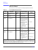
Troubleshooting Diagnostic Flowcharts Diagnostic Flowcharts The following table summarizes the types of network tests in the diagnostic flowcharts. Table 4-1 Chart Chapter 4 Type of Test Purpose 1 Cable and LED Test Checks that hardware, cables, and connectors between your system and card are operational. 2 Link Level Test Checks communication between link levels on source and target host using linkloop(1M). 3 Network Level Tests Validates arp(1M) entries and remote host availability.
Troubleshooting Diagnostic Flowcharts Flowchart 1: Cable and LED Test Checks that hardware, cables, and connectors between your system and card are operational.
Troubleshooting Diagnostic Flowcharts Flowchart 1 Procedures NOTE • Check dmesg/syslog output and look for error messages pertaining to gelan/igelan. Also, check nettl log messages. If errors, check card installation and reset and/or reseat card. • Verify LEDs. If 1000Base-SX link LED = OFF or for gelan, 1000Base-T all speed LEDs = ON, check card installation and reset and/or reseat card. If LEDs are then displayed correctly, continue to Link Level Test.
Troubleshooting Diagnostic Flowcharts Flowchart 2: Link Level Test Checks communications between link levels on source and target host using linkloop(1M).
Troubleshooting Diagnostic Flowcharts Flowchart 2 Procedures Chapter 4 • Execute linkloop(1M) to remote host. If linkloop is successful, continue to Network Level Tests. Otherwise, note which error was returned. • If loopback failed error = “Address has bad format” or “Not an individual address,” correct link level address with proper station address format/value and repeat Link Level Test. • Otherwise, loopback failed because remote host did not respond.
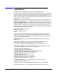
Troubleshooting Diagnostic Flowcharts Flowchart 3: Network Level Tests Validates arp(1M) entries and remote host availability. Checks communication between network layers on source and target host using ping(1M). Figure 4-3 Flowchart 3 Network Level Tests ARP Test ping Test Flowchart 3 Procedures 34 • See Flowchart 3a to validate arp(1M) entries and remote host availability. • See Flowchart 3b to check communication between network layers on source and target host using ping(1M).
Troubleshooting Diagnostic Flowcharts Flowchart 3a: ARP Test Validates arp(1M) entries and remote host availability. Figure 4-4 Flowchart 3a ARP Test Execute ping 2000 -n 1 Is remote host entry in ARP cache? NO Remote host up? YES NO YES Is the ARP entry correct and complete ? Bring up remote host NO Use ARP to correct and complete the entry YES ping Test Flowchart 3a Procedures Chapter 4 • Execute ping(1M) to remote host so that ARP entry is added.
Troubleshooting Diagnostic Flowcharts Flowchart 3b: ping Test Checks communication between network layers on source and target host using ping(1M). Figure 4-5 Flowchart 3b ping Test Execute ping 2000 NO YES Execute netstat -in.
Troubleshooting Diagnostic Flowcharts Flowchart 3b Procedures Chapter 4 • Execute ping(1M) to remote host. If ping is successful, continue to Transport Level Test. • If ping is not successful, execute netstat -in to verify MTU size. Ensure MTU size is the same on both local and remote hosts (9000 for jumbo frames and 1500 for standard frames) by executing lanadmin -M new_mtu nmid/ppa, and repeat ping Test.
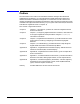
Troubleshooting Diagnostic Flowcharts Flowchart 3b (continued) Figure 4-6 Flowchart 3b (continued) ping not successful YES Network unreachable? error? Configuration Tests NO YES No response from ping? YES NO Unknown host error? Are you using jumbo frames? NO YES YES NO Reconfigure network Repeat ping Test Cable and LED Test Correct BIND, YP, or /etc/hosts configuration NO No route to host error? Do switches in the path support jumbo frames? Repeat ping Test YES Add route table entry
Troubleshooting Diagnostic Flowcharts Flowchart 3b (continued) Procedures Chapter 4 • If network unreachable error, go to Configuration Tests. • If there is no response from ping, and using jumbo frames, validate that switches in the path support jumbo frames, making sure path MTU is 9000 from source host to destination host. Otherwise, reconfigure network path and repeat ping Test. If not using jumbo frames, or switches and path MTU are set for jumbo frames (9000 bytes), go to Cable and LED Test.
Troubleshooting Diagnostic Flowcharts Flowchart 4: Transport Level Test Checks communications between transport layers on source and target host using telnet and ftp sessions.
Troubleshooting Diagnostic Flowcharts Flowchart 4 Procedures Chapter 4 • Execute telnet(1M) to a remote host. If successful, stop. • If not successful, try to establish an ftp to a remote host. Unlike telnet, ftp does not use a pseudoterminal (pty) driver on your system. This will determine if pty is why telnet failed. If ftp is successful, call your HP representative to determine why you have a problem with pty.
Troubleshooting Diagnostic Flowcharts Flowchart 5: Bridge/Gateway Loopback Test Checks general network connections through a gateway.
Troubleshooting Diagnostic Flowcharts Flowchart 5 Procedures Chapter 4 • Execute ping(1M) from a known good host through a gateway to another known good host. This will test connectivity through bridge/gateway level. If successful, execute netstat -r and examine route table on problem host and all hosts in path. If necessary, correct routing table and go to Network Level Tests. • If ping fails, examine gateway to see if HP 9000 or non-HP. If non-HP, refer to networking documentation for that product.
Troubleshooting Diagnostic Flowcharts Flowchart 6: Configuration Tests Verifies configuration of network interface on a host using ioscan(1M), lanscan(1M), netfmt(1M), lanadmin(1M), and ifconfig(1M).
Troubleshooting Diagnostic Flowcharts Flowchart 6 Procedures • Chapter 4 Verify configuration of network interface on a host using ioscan(1M), lanscan(1M), netfmt(1M), lanadmin(1M), and ifconfig(1M).
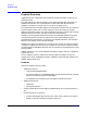
Troubleshooting Diagnostic Flowcharts Flowchart 6a: ioscan and lanscan Test Verifies configuration of network interface on a host using ioscan(1M) and lanscan(1M). Figure 4-10 Flowchart 6a ioscan and lanscan Test Is the card claimed by the system as shown by executing ioscan? Does lanscan show ExecuteUP Hardware for your interface? YES Does what /stand/vmunix display the gelan/igelan driver? Install driver using swinstall(1M) and verify or edit /stand/system to add driver keyword gelan/igelan.
Troubleshooting Diagnostic Flowcharts Flowchart 6a Procedures • Execute ioscan(1M) as follows: ioscan -kfd drivername, where drivername is either gelan or igelan (refer to Table 1-1, “List of Gigabit Ethernet Products”). Verify output from ioscan shows card “CLAIMED” by the system. Chapter 4 • If card is claimed, execute lanscan(1M) and check if the hardware state display shows “UP.” If so, go to Cable and LED Test. If not, continue to netfmt and lanadmin Test.
Troubleshooting Diagnostic Flowcharts Flowchart 6b: netfmt and lanadmin Test Verifies configuration of network interface on a host using netfmt(1M) and lanadmin(1M). Figure 4-11 Flowchart 6b netfmt and lanadmin Test Execute netfmt. Check causes and actions in the log output Problem solved? YES ifconfig Test NO Reset card ResetYES successful? YES Link Level Test NO Reset card once more; if still not successful, call HP.
Troubleshooting Diagnostic Flowcharts Flowchart 6b Procedures • Execute netfmt(1M) and view error and disaster log messages. Example: netfmt -vf /var/adm/nettl.LOG00 It will help to use the time stamp to find proper logs. Ensure you are looking at 1000Base-SX/T information. Chapter 4 • If problem is solved, continue to ifconfig Test. • If problem persists, run lanadmin(1M) to reset card. • If reset is successful, go to Link Level Test.
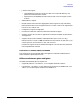
Troubleshooting Diagnostic Flowcharts Flowchart 6c: ifconfig Test Verifies configuration of network interface on a host using ifconfig(1M). Figure 4-12 Flowchart 6c ifconfig Test Execute ifconfig netmask up. Execute ifconfig ifconfig successful ? NO YES Are flags correct? NO Correct ifconfig flag settings YES Call HP ifconfig entry in YES /etc/rc.config.d/netconf ? NO Add network config for card to /etc/rc.config.
Troubleshooting Diagnostic Flowcharts Flowchart 6c Procedures • Execute ifconfig(1M) on the interface you want to configure to ensure that interface is enabled. Example: ifconfig lan1 192.6.1.17 netmask 255.255.255.0 up Next, execute ifconfig interface to test and verify flag setting is UP and correct IP address is displayed. Example: ifconfig lan1 Chapter 4 • If IP and flags are correct, verify there is an entry for card interface in /etc/rc.config.d/netconf.
Troubleshooting Diagnostic Flowcharts 52 Chapter 4
A Gigabit Ethernet lanadmin Display This appendix defines the terms listed in the lanadmin(1M) command display.
Gigabit Ethernet lanadmin Display LAN Interface Status Display LAN Interface Status Display The following is a sample of a lanadmin(1M) command display. The fields are defined in the section that follows. HP-UX 10.
Gigabit Ethernet lanadmin Display LAN Interface Status Display HP-UX 11.
Gigabit Ethernet lanadmin Display RFC 1213 MIB II RFC 1213 MIB II Following are descriptions of the statistics fields in the lanadmin(1M) command display. For more detailed information about the fields, refer to RFC 1213. Field Description Network Management ID A unique ID assigned by the system for the network management of each network interface. PPA Number A unique number assigned to each network interface, distinct from NMID.
Gigabit Ethernet lanadmin Display RFC 1213 MIB II Appendix A Inbound Octets The total number of octets received on the interface, including framing characters. Inbound Unicast Packets The number of subnetwork-unicast packets delivered to a high-layer protocol. Inbound Non-Unicast Packets The number of non-unicast (subnetwork-broadcast or subnetwork-multicast) packets delivered to a higher-layer protocol.
Gigabit Ethernet lanadmin Display RFC 1284 Ethernet-Like Interface Statistics RFC 1284 Ethernet-Like Interface Statistics Following are descriptions of the Ethernet-like statistics fields in the lanadmin(1M) command display. 58 Field Description Index A value that uniquely identifies an interface to an 802.3 medium. Alignment Errors A count of frames received on a particular interface that are not an integral number of octets in length and do not pass the FCS check.
B Gigabit Ethernet Card Statistics This appendix defines the card statistics that are output from the lanadmin(1M) command.
Gigabit Ethernet Card Statistics Card Statistics Output Card Statistics Output The following is a sample card statistics output. An explanation of the statistics is in the section that follows.
Gigabit Ethernet Card Statistics Explanation of Card Statistics Explanation of Card Statistics Following are descriptions of the card statistics that are output from the lanadmin(1M) command. Field Description Driver Statistics In Packet Error Number of inbound packets discarded because they were received when the driver was not operational or the packet length was incorrect.
Gigabit Ethernet Card Statistics Explanation of Card Statistics 62 Appendix B
C Hardware Reference Information This appendix contains information about the card LEDs, cabling requirements, and card specifications.
Hardware Reference Information The Meaning of the LEDs The Meaning of the LEDs The Link LED indicates the card’s status and must be on for the card to function properly. Note that there is no Link LED on the 1000Base-T card. In its place are three LEDs which indicate what speed (10, 100, or 1000 Mbps) the link has been established. The following tables show the LED description and status.
Hardware Reference Information Cabling Requirements Cabling Requirements Connectors on LAN cards adhere to appropriate standards agreed upon by various standards bodies and are widely available. The 1000Base-SX port is compatible with the IEEE 802.3z standard and uses a single duplex SC connector. The 1000Base-T port is compatible with the IEEE 802.3ab standard and uses an RJ-45 connector. Incorrectly wired or installed cabling is the most common cause of communications problems for local area networks.
Hardware Reference Information Card Specifications Card Specifications For compliance to European directives and related specifications, see the Declaration of Conformity statement in Appendix D. A4924A/A4925A/A4926A Physical Dimensions (HSC for K): 5.625 in by 3.25 in Dimensions (HSC for D/R): 13.375 in by 4.875 in Dimensions (PCI): 6.73 in by 4.75 in Electrical Power requirement (HSC): +15 watts max Power requirement (PCI): +14 watts max Environmental Temperature Degrees F = (1.
Hardware Reference Information Card Specifications VCCI Class A (PCI card only) Japan A4929A Physical Dimensions: 6.73 in by 4.75 in Electrical Power requirement: +14 watts max Environmental Temperature Degrees F = (1.
Hardware Reference Information Card Specifications A6825A/A6847A Physical Dimensions: 6.6 in by 2.5 in Electrical Power requirement: +8 watts max Environmental Temperature Degrees F = (1.8 x Degrees C) + 32 Operating Temperature: 0o C to 50o C Storage Temperature: -40o C to 60o C Humidity Operating Relative humidity range 5 to 95% non-condensing (40o C: 16 hour dwells at extremes) Non-operating/storage humidity: 5 to 95% non-condensing 20o C/hour Altitude Operating: 10,000 ft (3.
D Hardware Regulatory Statements This appendix contains regulatory statements for the United States, Canada, Australia/New Zealand, Japan, and the European community.
Hardware Regulatory Statements FCC Statement (For U.S.A.) FCC Statement (For U.S.A.) Federal Communications Commission Radio Frequency Interference Statement WARNING This device complies with Part 15 of the FCC rules. Operation is subject to the following two conditions: (1) This device may not cause harmful interference and (2) this device must accept any interference received, including interference that might cause undesired operation.
Hardware Regulatory Statements EMI (Australia and New Zealand) EMI (Australia and New Zealand) This product meets the applicable requirements of the Australia and New Zealand EMC Framework. VCCI (Japan) (PCI Card Only) This equipment complies with the Class A category for information technology equipment based on the rules of Voluntary Control Council for Interference by Information Technology Equipment. When used in a residential area, radio interference may be caused.
Hardware Regulatory Statements Laser Safety Statements Laser Safety Statements Laser Safety Statements - U.S. FDA/CDRH - Optical (laser) Transceiver CAUTION The optical transceiver provided on the network interface card contains a laser system and is classified as a “Class-I Laser Product” under a U.S. Department of Health and Human Services (DHHS) Radiation Performance standard according to the Radiation Control for Health and Safety Act of 1968.
Hardware Regulatory Statements Laser Safety Statements Appendix D 75
Hardware Regulatory Statements Laser Safety Statements 76 Appendix D
Hardware Regulatory Statements Laser Safety Statements Appendix D 77
Hardware Regulatory Statements Laser Safety Statements 78 Appendix D
Glossary Numerics F 1000Base-SX: A specific implementation of 1000Mbps operating over two multimode fiber cables, as specified in Standard IEEE 802.3z/D.50-1998. Fast Ethernet: A commonly used name applied to 100Base-T. 1000Base-T: A specific implementation of 1000 Mbps operating over four-pair Cat-5 or Cat-5e UTP cables, as specified in IEEE 802.3ab standards. A Alias: Name of the interface that corresponds to a given Internet address on a system.
Glossary Internet Address: The network address of a computer node. This address identifies both which network the host is on and which host it is. Refer to the Installing and Administering LAN/9000 Software manual for detailed information about network addressing. IP Address: See Internet Address. L LAN: See Local Area Network. Local Area Network (LAN): A data communications system that allows a number of independent devices to communicate with each other.
Glossary in the subnet address. Refer to Installing and Administering LAN/9000 Software for detailed information about subnet masks. Switch: A network interconnection device that allows multiple connected senders and receivers to communicate simultaneously in contrast to a hub (repeater) where only one device can send at a time. Some switches have fixed port speeds (10 or 100 Mbps) while others allow port speeds to be configured or autonegotiated.