345582-001.book Page 3 Friday, September 12, 2003 2:40 PM Drives Hard Drive This section discusses the primary hard drive of the notebook. Identifying the Hard Drive Activity Light The hard drive activity light turns on when the primary hard drive is being accessed.
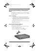
345582-001.book Page 4 Friday, September 12, 2003 2:40 PM Drives Removing and Installing a Primary Hard Drive The hard drive that is in the hard drive bay is the primary hard drive. The following sections describe how to remove and install the primary hard drive. Before You Begin 1. Save your work, exit all applications, and shut down the notebook. If you are not sure whether the notebook is off or in Hibernation, briefly press the power button.
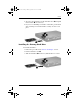
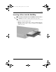
45582-001.book Page 5 Friday, September 12, 2003 2:40 PM Drives 5. To remove the hard drive, lift the hard drive door 1, and pull the hard drive 2 out of the bay. 6. If you are not installing a hard drive at this time, put the hard drive retaining screw and hard drive security screw in a safe place. Installing the Primary Hard Drive To install a hard drive: 1. Follow the procedure in the “Before You Begin” section. 2. Lift the hard drive door 1. 3.
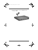
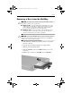
345582-001.book Page 6 Friday, September 12, 2003 2:40 PM Drives 4. Reinsert the hard drive security screw 1 and hard drive retaining screw 2.
345582-001.book Page 7 Friday, September 12, 2003 2:40 PM Drives MultiBay Drive This section explains how to use optional drives in the notebook MultiBay. Identifying the MultiBay Activity Light The MultiBay activity light turns on when any MultiBay device is active, with the exception of the MultiBay battery pack.
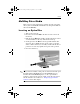
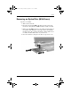
345582-001.book Page 8 Friday, September 12, 2003 2:40 PM Drives Inserting a Drive into the MultiBay inserting a hard drive into the MultiBay, insert the drive ✎ Before into a MultiBay hard drive adapter (purchased separately). 1. Turn the notebook upside down. 2. With the connector on the drive or drive assembly facing the MultiBay, slide the drive or drive assembly into the MultiBay until it is seated.
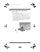
345582-001.book Page 9 Friday, September 12, 2003 2:40 PM Drives Removing a Drive from the MultiBay Ä CAUTION: To prevent system lockup and loss of information, stop the drive before removing it. To stop the drive: ■ ■ Ä Windows XP—Select the Safely Remove Hardware icon on the taskbar, then select the drive you want to remove. When it is safe to remove the drive, a message is displayed. (To display taskbar icons, select Show Hidden Icons in the system tray.
345582-001.book Page 10 Friday, September 12, 2003 2:40 PM Drives MultiBay Drive Media This section provides information on using optional optical disc drives (such as CD-ROM and DVD drives) and optional diskette drives in the MultiBay. Inserting an Optical Disc 1. Turn on the notebook. 2. Press the release button 1 on the drive bezel to release the media tray. 3. Pull out the tray 2 until it is fully extended. Position a CD or one-sided DVD over the tray with the label side up. 4.
345582-001.book Page 11 Friday, September 12, 2003 2:40 PM Drives Removing an Optical Disc (With Power) If power is available: 1. Turn on the notebook. 2. Press the release button 1 on the drive bezel to release the media tray, then pull the tray 2 out until it is fully extended. 3. Remove the disc 3 from the tray by gently pressing down on the spindle while lifting the outer edges of the disc. Handle the disc by the edges, not the flat surfaces.
345582-001.book Page 12 Friday, September 12, 2003 2:40 PM Drives Removing an Optical Disc (No Power) If power is unavailable: 1. Insert the end of a paper clip 1 into the manual eject recess in the front bezel of the drive. 2. Press in gently on the paper clip until the media tray is released, then pull out the tray 2 until it is fully extended. 3. Remove the disc 3 from the tray by gently pressing down on the spindle while lifting the outer edges of the disc.
345582-001.book Page 13 Friday, September 12, 2003 2:40 PM Drives Displaying Optical Disc Contents AutoPlay is enabled by default on the notebook. When an optical disc is inserted into a drive and AutoPlay is enabled, the contents of the disc display on the screen automatically. To display the contents of a disc when Autorun is not enabled: 1. Click Start > Run, then enter: X: where X = the designation of the drive containing the disc. 2. Press enter.
345582-001.book Page 14 Friday, September 12, 2003 2:40 PM Drives Resuming From Standby or Hibernation Ä CAUTION: To prevent possible video degradation and loss of audio or video playback functionality, do not initiate Standby or Hibernation while playing any media. If Standby or Hibernation is accidentally initiated while a drive medium (such as a diskette, CD, CD-RW, DVD, or DVD+RW) is in use, the following results can occur: ■ Your playback might be interrupted.
345582-001.book Page 1 Friday, September 12, 2003 2:40 PM 5 Audio and Video Using Audio Features The notebook includes the audio components described in the following table. Component Description 1 Audio line-out jack Connects optional powered stereo speakers, headphones, headset, or television audio. 2 Microphone jack Connects optional external monaural or stereo microphones.
345582-001.book Page 2 Friday, September 12, 2003 2:40 PM Audio and Video Component Description 3 Mute buttons Mutes the system volume. 4 Volume buttons (2) Adjust the system volume. Press the volume up button to increase sound. Press the volume down button to decrease sound. 5 Speakers (2) Produce system sound. Using the Audio Line-Out Jack Å WARNING: To reduce the risk of personal injury, adjust the volume before putting on headphones or a headset.
345582-001.book Page 3 Friday, September 12, 2003 2:40 PM Audio and Video Using the Microphone Jack When connecting a microphone to the microphone jack, use a single-sound channel (monaural) or dual-sound channel (stereo) microphone with a 3.5-mm plug. Monaural or stereo electret condenser microphones are recommended. ■ If you connect a monaural microphone, the recorded sound will be the same on both channels.
345582-001.book Page 4 Friday, September 12, 2003 2:40 PM Audio and Video Adjusting the Volume To adjust the volume, use any of the following controls: ■ ■ Notebook volume buttons ❏ To mute or restore volume, press the mute button. You can also mute or restore volume by pressing the volume up and volume down buttons simultaneously. ❏ To decrease the volume, press the volume down button. ❏ To increase the volume, press the volume up button. Windows Volume Control ❏ In Windows XP: a.
345582-001.book Page 5 Friday, September 12, 2003 2:40 PM Audio and Video Using Video Features The notebook features an S-Video-out jack which connects the notebook to an optional S-Video device, such as a television or overhead projector. The notebook can support one S-video device connected to the S-video out jack while simultaneously supporting an image on the notebook display or external display attached to the external monitor connector.
345582-001.book Page 6 Friday, September 12, 2003 2:40 PM Audio and Video Using the S-Video-Out Jack To connect a video device to the S-Video-out jack: 1. Plug either end of the S-Video cable 1 into the S-Video-out jack on the notebook. 2. Connect the other end of the cable 2 to the video device as instructed in the documentation included with the device.
345582-001.book Page 1 Friday, September 12, 2003 2:40 PM 6 Communication Devices Connecting a Modem Cable A modem cable, which has a 6-pin RJ-11 connector at each end, must be connected to an analog telephone line with, in some countries, the use of a country-specific modem adapter. Modem cables are provided with most notebooks, but may be purchased separately from most electronic retailers. Some notebooks may have been purchased without an internal modem.
345582-001.book Page 2 Friday, September 12, 2003 2:40 PM Communication Devices Ä CAUTION: Jacks for digital PBX systems might resemble analog telephone jacks but are not compatible with the modem. Ä CAUTION: Built-in modems may not work with multiple phone lines or a private branch exchange (PBX), cannot be connected to a coin-operated telephone, and do not work with party lines. Some of these connections may result in excess electrical voltage and could cause a malfunction in the internal modem.
345582-001.book Page 3 Friday, September 12, 2003 2:40 PM Communication Devices Connecting the RJ-11 Modem Cable To connect an RJ-11 modem cable: 1. If your notebook is equipped with an internal modem, plug the modem cable 1 into the RJ-11 telephone jack on the notebook. Å To reduce the risk of electrical shock, fire, or damage to the equipment, do not plug a modem cable into the RJ-45 network jack. 2. Plug the modem cable 2 into the RJ-11 telephone jack.
345582-001.book Page 4 Friday, September 12, 2003 2:40 PM Communication Devices Using a Country-Specific Adapter Cable Telephone jacks vary by country. To use the modem and the RJ-11 telephone cable outside the country in which you purchased the notebook, you must obtain a country-specific modem adapter. Refer to the Modem and Networking guide on the Documentation CD for more details about using your notebook internationally.
345582-001.book Page 5 Friday, September 12, 2003 2:40 PM Communication Devices Connecting a Network Cable A network cable has an 8-pin RJ-45 connector at each end. A network cable is provided with most notebooks, but may be purchased separately from most electronics retailers. If the network cable contains noise suppression circuitry, which prevents interference from TV and radio reception, orient the circuitry end of the cable toward the notebook.
345582-001.book Page 6 Friday, September 12, 2003 2:40 PM Communication Devices To connect the network cable: 1. Check that the existing LAN supports Ethernet 10BASE-T/100BASE-TX connections. 2. Plug the network cable 1 into the RJ-45 network jack on the notebook. 3. Plug the other end of the cable 2 into a network jack. 4. Start or restart the notebook. Windows Help for information about setting up and using ✎ See LAN connections. Select Start > Help and Support.
345582-001.book Page 7 Friday, September 12, 2003 2:40 PM Communication Devices Linking to an Infrared Device The notebook is IrDA-compliant—4-Mbps standard—and can communicate with another infrared-equipped device that is also IrDA compliant. The infrared port supports both low-speed connections of up to 115 Kbps and high-speed connections of up to 4 Mbps. Infrared performance may vary depending on the performance of infrared peripherals, distance between infrared devices, and applications used.
345582-001.book Page 8 Friday, September 12, 2003 2:40 PM Communication Devices Setting Up an Infrared Transmission For information about using infrared software, refer to your operating system Help file. To set up infrared devices for optimal transmission: ■ Prepare the infrared ports on both devices for transmission. ■ Position the devices so that their infrared ports face each other at a distance no greater than 1 meter (3.3 feet). ■ Position the ports so that they face each other directly.
345582-001.book Page 1 Friday, September 12, 2003 2:40 PM 7 External Devices The jacks and connectors described in this guide support standard external devices. ■ For information about which jack or connector to use, refer to the documentation included with the device. ■ For information about installing or loading any software required by the device, such as drivers, refer to the documentation included with the device. To connect a standard external device to the notebook: 1. Turn off the notebook. 2.
345582-001.book Page 2 Friday, September 12, 2003 2:40 PM External Devices Connecting a Monitor or Projector To connect an external monitor or projector to the notebook, insert the monitor cable 1 into the external monitor connector on the back of the notebook, and connect the other end of the cable 2 to a monitor or projector. a properly connected external monitor or projector does not ✎ Ifdisplay hotkey to switch the image to the an image, press the fn+f4 monitor.
345582-001.book Page 3 Friday, September 12, 2003 2:40 PM External Devices Using a USB Device Two Universal Serial Bus (USB) connectors can be used to connect external USB 2.0 and USB 1.1 devices, such as a USB keyboard, mouse, drive, printer, scanner, hub, or external MultiBay to the notebook. To connect a USB device to the notebook, insert the USB cable 1 into the USB connector on the back of the notebook, and connect the other end of the cable 2 to the external device.
345582-001.book Page 4 Friday, September 12, 2003 2:40 PM External Devices A USB device functions in the same way as a comparable non-USB device, with one exception. By default, USB devices do not function unless an operating system that supports USB is installed in the notebook. Some USB devices might require additional support software, which is usually included with the device. For more information and software installation instructions, refer to the documentation included with the device.
345582-001.book Page 5 Friday, September 12, 2003 2:40 PM External Devices Connecting an Optional External MultiBay An external MultiBay connects to the notebook by means of the USB connector and enables you to use MultiBay drives. For more information about external MultiBay drives, refer to the documentation that is included with such devices.
345582-001.book Page 6 Friday, September 12, 2003 2:40 PM External Devices Connecting a 1394 Device The IEEE 1394 connector can be used to connect an external device such as a digital camera, a digital camcorder, a high-speed storage device, or a scanner to the notebook. Some 1394 devices might require additional support software, which is usually included with the device. For more information and software installation instructions, refer to the documentation included with the device.
345582-001.book Page 7 Friday, September 12, 2003 2:40 PM External Devices Connecting an Optional Cable Lock purpose of security solutions is to act as a deterrent. These ✎ The solutions do not prevent the product from being mishandled or stolen. To install a security cable: 1. Loop the security cable around a secured object. 2. Insert the cable lock key 1 into the cable lock. 3. Insert the cable lock 2 into the security cable slot 3. 4. Turn the key and remove it from the cable lock.
5582-001.book Page 1 Friday, September 12, 2003 2:40 PM 8 Hardware Upgrades To order hardware or learn more about upgrades and accessories, visit the HP Web site at http://www.hp.com or refer to Worldwide Telephone Numbers booklet, included with the notebook, to contact an HP authorized dealer, reseller, or service provider. For information about obtaining and installing software updates and upgrades, refer to the “Software Updates and Restorations” chapter in the Software Guide on the Documentation CD.
345582-001.book Page 2 Friday, September 12, 2003 2:40 PM Hardware Upgrades Inserting a PC Card Ä■ CAUTION: To prevent damage to the connectors: ■ Use minimal pressure when inserting a PC Card into a PC Card slot. Do not move or transport the notebook while a PC Card is inserted. 1. Hold the PC Card label side up with the connector facing the notebook. 2. Gently push the PC card into the slot until the card is seated. The notebook will beep to indicate that a device has been detected.
345582-001.book Page 3 Friday, September 12, 2003 2:40 PM Hardware Upgrades Removing a PC Card Ä CAUTION: To prevent loss of work or an unresponsive system, stop the PC Card before removing it. 1. Stop the PC Card: ❏ In Windows XP—Select the Safely Remove Hardware icon on the taskbar, then select the PC Card. (To display the Safely Remove Hardware icon, right-click the taskbar and select Show Hidden Icons.
345582-001.book Page 4 Friday, September 12, 2003 2:40 PM Hardware Upgrades Using SD Cards Secure Digital (SD) Cards are removable thumbnail-sized compact flash storage devices that provide a convenient method of storing data and sharing it with other devices such as PDAs, cameras, and other SD-equipped PCs. Inserting an SD Card Ä■ CAUTION: To prevent damage to the connectors: ■ Use minimal pressure when inserting an SD Card into an SD Card slot.
345582-001.book Page 5 Friday, September 12, 2003 2:40 PM Hardware Upgrades Removing an SD Card Ä CAUTION: To prevent loss of work or system lockup, stop the SD Card before removing it. To remove an SD Card: 1. Close all files and applications that are using the SD Card. 2. Stop the SD Card: Ä ❏ In Windows XP, select the Safely Remove Hardware icon in the taskbar, then select the PC Card. (To display the Safely Remove Hardware icon, right-click the taskbar and select Show Hidden Icons.
345582-001.book Page 6 Friday, September 12, 2003 2:40 PM Hardware Upgrades 3. Gently press in on the SD Card 1 to unseat it. 4. Pull the SD Card 2 from the slot. Adding and Upgrading Memory Modules Å WARNING: The memory compartments are the only user-accessible internal compartments on the notebook. All other areas that require a tool to open should be opened only by an authorized service provider.
345582-001.book Page 7 Friday, September 12, 2003 2:40 PM Hardware Upgrades The notebook has 2 memory slots, one on top of the other, located under the keyboard. The memory expansion slot 1 is on top of the primary memory slot 2. One or both of these slots may be populated at the factory. The memory capacity of the notebook can be upgraded by adding a memory module to the expansion slot or by upgrading the existing memory module in the primary memory slot. Before You Begin 1.
345582-001.book Page 8 Friday, September 12, 2003 2:40 PM Hardware Upgrades Removing the Memory Module To remove a memory module: 1. Follow the procedure in the “Before You Begin” section. 2. Remove the 2 keyboard access screws from the bottom of the notebook. (A keyboard icon is located next to both keyboard access screws.
345582-001.book Page 9 Friday, September 12, 2003 2:40 PM Hardware Upgrades 3. Open the notebook and slide the 4 keyboard latches down 1 to release the keyboard, then tilt the keyboard up 2 and remove it from the notebook.
345582-001.book Page 10 Friday, September 12, 2003 2:40 PM Hardware Upgrades 4. Press in on the latch 1 to release the memory slot cover 2, then tilt it up and remove it from the notebook. If you are replacing the existing memory in the primary memory slot, you must remove any memory in the memory expansion slot first. Proceed to step 5. If you are adding memory to the memory expansion slot, see “Adding a Memory Module” later in this chapter.
345582-001.book Page 11 Friday, September 12, 2003 2:40 PM Hardware Upgrades 5. To remove a memory module from the memory expansion slot: a. Pull the retention clips 1 away from each side of the module. The module tilts upward when released. b. Lift the edge of the memory module 2 and gently remove it from the slot. Ä To protect a memory module after it has been removed, place it in a static-safe container. Repeat step 5 to remove the memory module from the primary memory slot, if necessary.
345582-001.book Page 12 Friday, September 12, 2003 2:40 PM Hardware Upgrades Adding a Memory Module 1. Follow the procedures in the “Before You Begin” section. 2. To insert the new memory module into either memory slot: a. Align the keyed (notched) edge of the module 1 with the keyed area in the expansion slot. b. Press the module into the slot from a 45-degree angle until it is seated, then press the module 2 downward until the retention clips snap into place. 3. Replace the memory slot cover. 4.
345582-001.book Page 13 Friday, September 12, 2003 2:40 PM Hardware Upgrades Effects of Increasing Memory When memory increases, the operating system increases the hard drive space reserved for the Hibernation file. If you experience problems with Hibernation after memory has been increased, verify that your hard drive has enough free space to accommodate a larger Hibernation file. ■ To display the amount of memory (RAM) in the system: ❏ Press fn+esc.
345582-001.book Page 1 Friday, September 12, 2003 2:40 PM 9 Specifications The information in this chapter might be helpful if you plan to use or transport the notebook internationally or in extreme environments. only compatible AC adapters and battery packs with the ✎ Use notebook. For additional information, visit the HP Web site at http://www.hp.com or use the Worldwide Telephone Numbers booklet, included with your notebook, to contact an HP authorized dealer.
345582-001.book Page 2 Friday, September 12, 2003 2:40 PM Specifications Notebook Dimensions Dimension Metric U.S. Height 3.66 cm 1.44 in Width 32.59 cm 12.83 in Depth 27.51 cm 10.83 in Operating Environment Factor Metric U.S.
345582-001.book Page 3 Friday, September 12, 2003 2:40 PM Specifications Rated Input Power Input power Rating Operating voltage 100 to 120/220 to 240 VAC RMS Operating current 1.7/0.85 A RMS Operating frequency range 47 to 63 Hz AC When powered by a DC source 18.5 V MAX ✎ This product is designed for IT power systems in Norway with phase-to-phase voltage not exceeding 240 Vms. Modem Specifications This notebook has been tested and found to comply with the limits for a Class B digital device.
345582-001.
345582-001.book Page 2 Friday, September 12, 2003 2:40 PM Index MultiBay 3–2, 3–4, 4–2 primary 3–2, 3–3 removing 3–3 storing 3–1, 3–19 See also battery power battery power conserving 3–17 low-battery conditions 3–11 running notebook on 3–1 See also battery packs battery release latch 1–14 battery slot 1–8 battery, primary bay 1–8 release latch 1–8 bay.
345582-001.book Page 3 Friday, September 12, 2003 2:40 PM Index conserving power 3–17 country-specific modem cable adapter 6–4 critical low-battery condition identifying 3–11 restoring from 3–12 D device drivers external devices 7–1 PC Card 8–1 digital vs.
345582-001.
345582-001.
345582-001.
345582-001.
345582-001.