HP AdvanceStack 10BT Management Module Installation and Reference Guide
© Copyright 1996 Hewlett-Packard Company All Rights Reserved. This document contains information which is protected by copyright. Reproduction, adaptation, or translation without prior permission is prohibited, except as allowed under the copyright laws.
Contents 1 Installing the Management Module Installation Steps . . . . . . . . . . . . . . . . . . . . . . . . . . . . . . . . . . . . . . . . . . . . . 1-1 Removing the Module . . . . . . . . . . . . . . . . . . . . . . . . . . . . . . . . . . . . . . . . . . 1-6 2 Management Module Features Port Switching . . . . . . . . . . . . . . . . . . . . . . . . . . . . . . . . . . . . . . . . . . . . . . . . 2-2 Increasing Throughput with HP Switching Hubs . . . . . . . . . . . . . . . . .
Using the Console . . . . . . . . . . . . . . . . . . . . . . . . . . . . . . . . . . . . . . . . . . . . . 3-6 Port Counters . . . . . . . . . . . . . . . . . . . . . . . . . . . . . . . . . . . . . . . . . . . . . . . 3-8 Segment Counters . . . . . . . . . . . . . . . . . . . . . . . . . . . . . . . . . . . . . . . . . . . 3-9 4 Removing A Hub From a Stack Number of Hubs Allowed In the Stack . . . . . . . . . . . . . . . . . . . . . . . . . . 4-2 Reinserting a Hub into a Stack . . . . . . . . . . . . . .
D Network Addressing Communication Between the Hub and Network Management Station . . . . . . . . . . . . . . . . . . . . . . . . . . . . . . . . D-1 IPX Addressing for Novell Netware . . . . . . . . . . . . . . . . . . . . . . . . . . . D-2 IP Addresses for IP and Non-IP Networks . . . . . . . . . . . . . . . . . . . . . D-3 Setting the IP Address for a Hub . . . . . . . . . . . . . . . . . . . . . . . . . . . . . . D-3 Using Bootp . . . . . . . . . . . . . . . . . . . . . . . . . . . . . . . . . . . . . .
HP Customer Support Services How to get the latest software/agent firmware You can download the following: HP Management Module firmware: j3210a.exe from the HP BBS, HP FTP Library Service, CompuServe, and the World Wide Web. After you download the file, extract the file by typing: filename /x. For example, j3210a.exe /x HP BBS Set your modem to no parity, eight bits, 1 stop bit, set speed up to 14400 bps, and with your telecommunication program (e.g.
HP FIRST Fax Retrieval Service HP FIRST is an automated fax retrieval service that is available 24 hours a day, seven days a week. HP FIRST provides information on the following topics: ■ Product information ■ Troubleshooting instructions ■ Technical reviews and articles ■ Configuration information To access HP FIRST, dial one of the following phone numbers: Location Phone Number U.S. and Canada Only Dial 1 (800) 333-1917 with your fax machine or touch-tone phone and press 1. Outside the U.S.
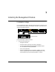
1 Installing the Management Module Installation Steps The HP J3210A AdvanceStack 10BT Management Module is installed into the front of the HP AdvanceStack Switching Hub. Hereafter, the module will be called the Management Module. Management Module Active Base MAC Address Follow these steps to install the module: 1.
Installing the Management Module Installing the Management Module Installation Steps Caution 2. Static electricity can severely damage the sensitive electronic components on the module. When installing the module in your hub or when inserting a SIMM onto the module, follow these procedures to avoid damage from static electricity: • Handle the module or SIMM by its edges and avoid touching the components and the circuitry on the board.
Installing the Management Module Installation Steps 6. cover plate Loosen these screws 7. Insert the Management Module into the hub. Leading with the hub connector edge, line up the sides of the module with the rails on the sides of the hub’s slot. Then push the module into the slot until it is firmly seated in the connector in the back of the slot. Management Module Active Base MAC Address 8. Tighten the two screws that hold the module in place. Be careful not to overtighten the screws. 9.
Installing the Management Module Installation Steps Installing the Management Module 11. Turn on the power to the hub with the Management Module and then provide power to the rest of the hubs in the stack. Provide power by plugging in the power cord to the hub. During power-on, the following occurs: At Power On Hub begins power-on self test followed by the module’s self test. Ports are temporarily disabled until the Management Module configures the ports. During Self-Test All Module LEDs are on.
Installing the Management Module Installation Steps Installing the Management Module You have now completed installation and verification of the module. The hardware features of this module are as follows: Active Base MAC Address LED or Button Status Description Active ON Specifies this module is the primary module if a second module is in the stack. OFF This module is the redundant module in the stack and will take over if the primary module fails.
Installing the Management Module Installing the Management Module Removing the Module Removing the Module The module is removed from the hub by reversing the installation steps described earlier in this document. To remove the module, follow these steps: 1. Remove power from the hub by unplugging the power cord. 2. Remove the Extender Cable(s). 3. Unscrew the two captured screws holding the module. 4. Pull the module out of the slot. 5.
2 Management Module Features With the Management Module, you can now address the problems of a busy and growing network with the following features: ■ Port Switching. Gives you the ability to move ports onto one of four network segments to increase network throughput ■ Management.
Management Module Features Port Switching Port Switching } Management Module Features Seg m Seg ent 1 m Seg ent 2 me Seg nt 3 men t4 Within each Switching Hub, there are four distinct network segments, as if there were actually four hubs in one. These segments run through an entire stack of hubs through the Extender Cable. Port switching is the ability to move ports from one segment to another through software rather than physically moving cables in the wiring closet.
Management Module Features Port Switching Communication Between Hubs When Users Are on the Same Segment Users can communicate with each other on the same segment in the stack through the Extender Cable. The following example shows two hubs with users on segment 2. Segments Example Segment 2 (Engineering) Hub B Segment 2 (Engineering) Users on Hub A and Hub B can talk to each other because they are on the same segment.
Management Module Features Port Switching Communication Between Segments Communication between the segments can be achieved through: ■ ■ ■ multiple LAN adapters in the server switch router For example, add an external switch or Switch Module to your stack if you want users (for example) on segment 2 to talk to users on segments 1 and 3.
Management Module Features Port Switching Note If you have not moved ports to segments 2-4, then port LEDS will be lit after you press the Segment Display button once. This is because all ports are on segment 1. Example of using the Segment Display Button Example: Network administrator wants to know which ports Ports 1, 4-8 are now lit. are on Segment 2. Active Base MAC Address Press Segment Display button twice. Segment 2 LED is lit. .
Management Module Features Management Management When you install the Management Module, it has four MAC addresses. One MAC address is for each of the four segments. The Management Module shows the base MAC address for segment 1. Add one to this address to get the MAC address for segment 2, add one more for segment 3, etc.
Management Module Features Management Resetting the Stack with Management If you install an optional Management Module, its reset button resets the entire stack of hubs. The hubs are reconfigured and counters are reset to zero. This can also be done through the ASCII console or HP AdvanceStack Assistant. From the ASCII console, you can also change the hub back to its default settings. The default settings are all ports enabled, security violations cleared, and all ports are placed back on segment 1.
Management Module Features Advanced Management: RMON and EASE Support Advanced Management: RMON and EASE Support The Management Module supports RMON (Remote Monitoring) and EASE on all four segments. This allows for troubleshooting and optimizing of your network.
3 Configuring the Switching Hubs in Software Two Network Management Interfaces The Management Module Pack includes two software user interfaces through which you can manage, configure, and troubleshoot your stack of hubs. The two interfaces are: ■ HP AdvanceStack Assistant (formerly called HP Interconnect Manager) ■ ASCII console Depending on your hardware and management needs, choose which application best fits your needs. HP AdvanceStack Assistant runs on Windows 95 or NT 3.
Configuring the Switching Hubs in Software Two Network Management Interfaces ■ reset a specific hub to factory defaults (ASCII console only) ■ enable and disable ports ■ display security violations and clear them ■ create backup link configuration ■ select the active management module (useful when using redundant management) HP AdvanceStack Assistant Features Configuring the Switching Hubs in Software HP AdvanceStack Assistant is an SNMP-compliant network management product that gives you the fe
Configuring the Switching Hubs in Software Connecting to the ASCII Console Connecting to the ASCII Console You can begin a console session with the hub in the following ways: ■ directly, using a serial cable and a terminal (or a PC using a terminal emulator) ■ remotely, using Telnet ■ remotely, using a modem and a terminal/PC The Management Module supports a single console session only. If a console session is already running, a second console session can override the first console session.
Configuring the Switching Hubs in Software Connecting to the ASCII Console Remotely, Using Telnet The Management Module support a Telnet console session. Your Telnet syntax depends on your TCP/IP software or your terminal server. By default, Telnet is enabled. You can disable Telnet by using the “Connection Configuration” screen in the ASCII console. To establish a Telnet session, follow these steps: 1.
Configuring the Switching Hubs in Software Connecting to the ASCII Console Remotely, Using a Modem and a Terminal Use two full-duplex, asynchronous (character-mode) modems only. A list of tested modems and their initialization strings are in appendix C, “Modem Configuration”.
Configuring the Switching Hubs in Software Using the Console Using the Console The console session starts with a display similar to the following (the actual version numbers may be different): HP J3210A Switching Hub 10BT Management Module ROM A.01.00 EEPROM A.01.00 HW A.01.00 Use HP AdvanceStack Assistant commands for graphical hub configuration. Type MENU to access the ASCII menu system, or HE or? for help on console commands.
Configuring the Switching Hubs in Software Using the Console Option Description Hub Status and Counters Displays counters, system name, system contact, system up time, segment MAC addresses, hub port status. See the tables on the next two pages for segment and port counters. IP/IPX Configuration Enable/disable IP/IPX for each segment, and set addresses. For an IP address, see the instructions in appendix D, “Network Addressing”.
Configuring the Switching Hubs in Software Using the Console Port Counters Configuring the Switching Hubs in Software The port counters are from the IEEE 802.3 Repeater Management Specification. They are described below: Counter Name Definition Valid Range Corrective Action if over Valid Range Good Packets Number of error-free packets received. Less than 4000 packets per second.* Decrease the traffic level by using a switch to segment the network.
Configuring the Switching Hubs in Software Using the Console Segment Counters The Segment counters are from the RFC 1757 RMON MIB Specification. Their definition of counters is different than IEEE 802.3 Repeater Management Specification as describe din this table. Definition Valid Range Corrective Action if over Valid Range Good/Bad Packets Number of error free and errored packets. Less than 4000 packets per second.* Decrease the traffic level by using a switch to segment the network.
4 Removing A Hub From a Stack This chapter covers the following: ■ number of hubs in a stack ■ reinserting a hub into an existing stack 4-1
Removing A Hub From a Stack Number of Hubs Allowed In the Stack Number of Hubs Allowed In the Stack The maximum size of a hub stack is eight hubs. If more than eight hubs are in the stack, management software (HP AdvanceStack Assistant and the ASCII console) will disable ports on that hub. Also, the Extender Cable connection on the ninth hub will be disabled, so that the ninth hub is not allowed to communicate with the stack. No configuration will be possible on extra hubs in a stack.
Removing A Hub From a Stack Reinserting a Hub into a Stack Reinserting a Hub into a Stack If a removed hub is re-inserted back into the same stack, the Management Module remembers all of the configuration for that hub. The reinserted hub will quickly reconnect to the network and this hub will automatically be reconfigured to the same port settings it had before it was removed. Management Module Removed hub reinserted into the stack keeps configuration.
Removing A Hub From a Stack Reinserting a Hub into a Stack Top or Bottom Hub: If you disconnect a hub at the top or bottom of the stack, then the hubs in the middle will still communicate. Stack Example 1 Stack Example 2 Top hub removed Management Modules A middle hub removed. Bottom hub removed All hubs in the middle can communicate with each other. Top hub can’t communicate with rest of stack. Remove an Extender Cable and connect hubs together.
5 Troubleshooting This chapter describes how to troubleshoot your Management Module and how to troubleshoot your stack of hubs for cabling problems. This chapter covers these topics: ■ using the problem/solution table ■ IP configuration errors ■ diagnostic tests ■ clearing a password for the ASCII console Use the following table to diagnose the problem with your Management Module: Problem Solution How do I reset the stack of hubs? Either: Push the reset button on the primary Management Module.
Troubleshooting Troubleshooting Problem Solution I am through looking at segment information. I want to see if each cable is connected correctly. Either: - After you press the Segment Display button, wait 60 seconds and then link status information will show in the port LEDs. -Press the Segment Display button until all Segment Display LEDs (1, 2, 3, and 4) are off. I can’t remember the console password to configure and diagnose the hubs.
Troubleshooting IP Configuration Errors Solution I think the active Management Module isn’t working anymore because the Fault LED is on. I don’t have a redundant Management Module in the stack. What do I do? Attempt to reset the stack by pressing the reset button on the Management Module. If the problem still occurs, download a current or new firmware version from the web, BBS, or CompuServe. See the perforated card at the beginning of this manual for more instructions.
Troubleshooting Diagnostic Tests Troubleshooting Diagnostic Tests The HP AdvanceStack Assistant and ASCII console provide tests and indicators that can be used to monitor the hub and its network connections. Testing the Hub Only If you believe that the hub is not operating correctly, remove and reinsert the power cord for that hub. This procedures will cause the hub to complete its power-on self-test. If any error conditions exist in the hub, the LEDs should display the condition.
Troubleshooting Diagnostic Tests Testing the Hub’s Ports and the Links ■ Select Link Test from HP AdvanceStack Assistant’s Network Test function or the ASCII console’s Connectivity Tests. This causes the hub to send IEEE 802.2 Test command packets to a specified network device out a specified segment. The device must be able to send an IEEE 802.2 Test response packet upon receipt of a Test command packet. Usually this would be another network device such as a hub, switch or router.
to execute these tests. Clearing a Password for the ASCII Console You can use the Segment Display button to clear a forgotten console password that was previously configured on the hub. You can clear the password to access the Management Module. The password is configured from the ASCII console. To clear the password, follow these steps: 1. Verify the hub has powered-up, passed self-test, and that the active LED is lit for the Management Module. 2.
Troubleshooting HP Customer Support Services HP Customer Support Services ■ CompuServe ■ HP BBS ■ HP FIRST Faxback ■ World Wide Web These services can be used to update your firmware or get information about existing or new products. See the perforated card at the beginning of this manual for more information.
A Cables and Connectors This appendix lists cables that have been tested and verified for use with the HP Management Module. It also includes minimum pin-out information so, if you wish to use an unlisted cable, you can verify that the cables used in your installation are correctly wired. Note that each pin-out does not necessarily match the pin-out for the corresponding HP cable, but cables manufactured to follow the minimum pin-out will function correctly.
Cables and Connectors RS-232 Connector and Cable Pin-Outs RS-232 Connector and Cable Pin-Outs The Management Module’s RS-232 port connector is wired as depicted in the following table. Cables and Connectors PIN US CCITT DIN 1 DCD 109 M5 2 Rx 104 D2 3 Tx 103 D1 4 DTR 108 S1 5 GND 102 - 6 DSR 107 M1 7 RTS 105 S2 8 CTS 106 M2 9 RI 125 M3 Use the RS-232 port to connect a PC to be used as the console.
Cables and Connectors RS-232 Connector and Cable Pin-Outs A Minimum Cable Pinout for ASCII Console Connection PC end 9-pin male Hub end 9-pin male 2 2 Rx 3 3 Tx 5 5 GND Cables and Connectors RS-232 Modem Cable Modem end 25-pin male Hub end 9-pin male 2 3 Tx 3 2 Rx 4 7 RTS 5 8 CTS 6 6 DSR 7 5 GND 8 1 CD OR DCD 20 4 DTR 22 9 RI 23 Signal DRS–typically on V.
B Specifications Physical Width 15.5 cm (6.1 in) Depth 11.8 cm (4.6 in) Height 4.4 cm (1.7 in) Weight 1.3 kg (.28 lb) Environmental Operating Non-Operating Temperature +0°C to +55°C (32°F to 131°F) -40°C to 70°C (-40°F to 158°F) Relative humidity (non-condensing) 15% to 95%at 40°C (104°F) 15% to 90% at 65°C (149°F) Maximum altitude 4.6 km (15,000 ft) 4.6 km (15,000 ft) Connectors The RS-232-C console port conforms to V.22 bis.
Specifications Safety Complies with IEC 950: (1991)+A1,A2/.
Specifications Management Protocols RFC 1157 SNMP RFC 1901-1908 SNMPv2C RFC 1420 SNMP over IPX Support MIBS IIETF 802.3 Repeater MIB IETF Entity MIB RFC 1213 MIBII RFC 1515 MAU MIB RFC 1573 Interface Evolution MIB RFC 1650 Ethernet MIB RFC 1757 RMON MIB HP MIB Extensions Available on request.
Specifications Regulatory Statements FCC Statement (For U.S.A. Only) Federal Communications Commission Radio Frequency Interference Statement Note: This equipment has been tested and found to comply with the limits for a Class A digital device, pursuant to Part 15 of the FCC Rules. These limits are designed to provide reasonable protection against harmful interference when the equipment is operated in a commercial environment.
C Modem Configuration Before installing the modems (one attached to the hub and one attached to the terminal/PC), configure them by either issuing the appropriate AT command or by setting the modem’s switches, as described in the tables in the rest of this appendix. Hayes Smartmodem Optima 28.8 (V.
Modem Configuration Megahertz XJ2288 PCMCIA card modem At the user end: Issue the following AT command: AT&FW2&C1&D3&K3\J0\N3\Q3\V1%C1"H3S7=60) Hayes V-Series ULTRA Smartmodem 14400 At the hub end: Issue the following AT command: AT&FS0=1&D2&S2&Y0&W0=60S0=1&W At the user end: Issue the following AT command: AT&F&Y0&WO=60 Practical Peripherals PM288MT II V.
D Network Addressing Communication Between the Hub and Network Management Station When an HP Management Module (HP J3210A) is installed in a stack of hubs, they can be managed over the network by HP network management products, for example HP AdvanceStack Assistant. These hubs can also be managed by any other network management products that comply with the Simple Network Management Protocol (SNMP) standard and have standard SNMP MIBbrowser functionality.
Network Addressing IPX Addressing for Novell Netware Network Addressing IPX Addressing for Novell Netware The Novell Netware network operating system uses a protocol called Internetwork Packet Exchange (IPX). The IPX protocol firmware is always available on an HP Switching Hub stack that has a Management Module and so you do not need to do any configuration.
Network Addressing IP Addresses for IP and Non-IP Networks If you have chosen to manage your hub with an SNMP/IP network manager, your Management Module in your hub must be configured with an IP address. If your network will be connected with other networks that use IP addresses, you must use assigned IP addresses. Otherwise, you can build your own IP addressing scheme.
Network Addressing Using Bootp Network Addressing Using Bootp Bootp (Internet Boot Protocol) is used to download network configuration data from a server (the Bootp server) to the hub.
E Backup Links Examples of Backup Links With the Management Module in a stack of hubs, the Backup Link function allows you to specify a backup link between two devices in case the primary link fails.
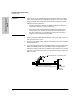
Backup Links Examples of Backup Links Management Module Backup Link (crossover twisted-pair) Two Hub Stacks Primary Link (fiber) thin coax cable for non-segmented hubs AdvanceStack Hub Stack 2 Backup Links Switching Hub Stack 1 SNMP Server A backup link is a separate path connected between the hub and a device. The port through which the cable is connected between the two devices is automatically enabled if the connection designated as the primary link fails.
Backup Links Examples of Backup Links Note One hub in the stack needs an HP Management Module installed. ■ The port used for the primary link must be on a segment this is connected to (not isolated from) the main four-segment backplane. ■ The port used for the backup link can be on a connected or isolated segment, however it is recommended that you put the primary and backup link on the same segment. ■ Any combination of media types can be used as a backup link by using the AUI/Xcvr slot.
Backup Links Configuring a Backup Link Configuring a Backup Link Configure the Monitoring Hub Only. All configuration of the backup links feature is performed from HP AdvanceStack Assistant or the ASCII console. On the “remote” device, you only need to make sure the ports used for the primary and backup links are both enabled. Backup Links Use the Backup Function. To configure this link, you use the Backup function in HP AdvanceStack Assistant or the ASCII console.
Backup Links Identifying the Backup Link Configuration/Installation Sequence If a hub is installed in a network that includes two connections to another hub, and the backup link has not yet been configured, a loop in the network now exists that will cause some network performance degradation. For this reason, it is better to configure the backup link on the hub before the hub is installed in the network.
Backup Links Indications of Backup Link Activation Indications of Backup Link Activation When the primary link fails (“n” consecutive test packet responses were not received on the primary port from the other device), the backup link is automatically enabled. The effect of this change is displayed on the monitoring hub's LEDs and management interface. Activation of the backup link does not change the status of any of the ports on the remote device.
Index A D ASCII console features … 3-1 ASCII console, methods of accessing … 3-3 default settings … 2-7 diagnostic tests … 5-4 testing the hub only … 5-4 testing the ports and links … 5-5 B E backup link configuration process … E-4 description … E-1 identification … E-5 indications of activation … E-6 limitations … E-3 operational notes … E-3 reactivating the primary link … E-6 BOOTP … D-4 example BOOTP table entry … D-4 broadcast packets definition … 3-8, 3-9 EASE description … 2-8 encapsulation … D
I N included parts … 1-1 installing extra memory … 1-2 module … 1-1, 2-1 Interconnect Manager.
S Security Configuration ASCII console … 3-7 segment isolating … 3-7 Segment Display button using … 2-4 Segmentation displaying in Port LEDs … 2-4 self-test … 1-4 serial cable connection … 3-3 SIMM, installing … 1-2 stack number of hubs allowed in … 4-2 reinserting a hub into … 4-3 removing a hub … 4-3 switch communication between segments … 2-4 T Telnet connection … 3-4 disabling … 3-4 testing ports and links … 5-5 troubleshooting diagnostic tests … 5-4 IP configuration errors … 5-3 IPX test … 5-5 link te