
HP Integrated Lights-Out Security, 7th edition


4
• Reprogram the iLO ROM
• Reprogram the boot block
Security in hardware design
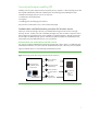
iLO includes a 32-bit, PCI-based ASIC that contains a RISC processor core with separate instruction
and data caches, a memory controller, SDRAM, NVRAM, management ROM, and NIC (Figure 1).
Figure 1. Block diagram of iLO processor
Management ROM
The management ROM includes the iLO boot block and the iLO main firmware image. The iLO boot
block provides iLO hardware and software setup, locates and validates an executable firmware
image, and transfers control to the executable image.
The iLO main image includes an RSA
1024-bit private/public digital signature. HP signs the firmware
image with the private key known only to HP. The iLO boot block knows the public key. HP uses this
firmware build process to produce the signed image:
1. Compute an SHA 1 (Secure Hash Algorithm) hash over the entire image.
2. Encrypt and sign the SHA1 hash with the RSA private key.
3. Store the encrypted signature in the image header.
The iLO boot block performs the following steps to validate and boot the signed firmware image:
1. Searches memory for a viable image with a recognizable header.
2. Decrypts the signed SHA1 hash using the RSA public key.
3. Computes the SHA1 hash over the entire image.
4. If the two SHA1 hashes match, the image is valid and the boot block passes control to the iLO
main image to begin executing.
iLO
RISC
Processor
iLO
Mgmt
Port
Auxiliary-powered
System-powered
SDRAM
Host
PCI
Bus
10/100
NIC
Host
Firewall/
Bridge
System
Health
Monitoring
Host Power/
Fault Isolation
Mgmt
ROM
Memory Controller
Console
Redirection
Virtual
Media
Server
NIC
Host
Server
Port
NVRAM
Temporary ROM data path
(closed after firmware boot block executes)