
Manual


Overview of the Tape Drive
5158ACL Tape Drive Installation and User’s Guide—524955-002
1-2
Power Supply
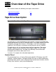
The display provides a highly intelligible display of drive and loader status, menu
choices and error messages. The amount of information available to the
operator is greatly expanded by the scrolling feature.
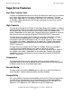
Power Supply
The AC power switch is located on the front panel of the tape drive. The nominal
voltages are 115 VAC and 240 VAC, and the autoranging power supply adjusts
automatically to either of the two operating voltages. The power supply can
operate at 50 or 60 Hz without requiring any modification.
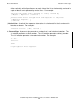
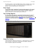
Tape Cartridge Magazine
The 10-cartridge tape magazine is accessible through the door at the center of
the front panel. An electronically controlled lock on the door protects against
tampering and inadvertent removal. The magazine fits into a extruded track that
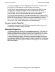
assures precise robotics positioning. Figure 1-2 shows a 10-cartridge tape
magazine. Insertion and removal of the magazine is described in Operating the
Tape Drive.
Figure 1-2. 10-Cartridge Tape Magazine
Integral Fan Cooling
To provide optimum cooling for critical parts, a single forced-air fan is mounted
on the rear panel. It also prevents the tape drive and robotics electronics,
motors and power supply from overheating.