HP Point of Sale (POS) Peripherals Configuration Guide Document Version 3.
© Copyright 2019 HP Development Company, L.P. The information contained herein is subject to change without notice. Microsoft, MS-DOS, Windows, WEPOS, POSReady and Windows NT are trademarks of Microsoft Corporation in the U.S. and other countries. The only warranties for HP products and services are set forth in the express warranty statements accompanying such products and services. Nothing herein should be construed as constituting an additional warranty.
Contents 1 Introduction................................................................................................................................... 11 2 General Information ..................................................................................................................... 11 2.1.1 Where to obtain the latest software for the HP POS Peripherals ..................................... 11 2.1.2 OPOS and CCO Drivers/Application ...........................................................
6.3.6 6.3.5.1 HP Integrated OPOS Cash Drawer Utility .......................................................... 58 6.3.5.2 OPOS Cash Drawer and Printer Utility .............................................................. 61 JPOS Drivers for the Integrated Cash Drawer Port .......................................................... 65 6.3.6.1 JPOS Test Applet for the Integrated Cash Drawer Port .................................... 65 6.4 HP USB Cash Drawer ................................................
6.5.17 6.5.18 6.5.19 6.5.20 6.5.21 6.5.22 JPOS Drivers for the Receipt Printer Drivers - CheckScanner ....................................... 225 JPOS Drivers for the Receipt Printer Drivers - MICR ..................................................... 232 JPOS Drivers for the Receipt Printer Drivers – Slip Printing........................................... 238 JPOS Drivers for the Receipt Printer Drivers – Barcode Testing.................................... 245 JPOS Drivers for the Cash Drawer Drivers ...
.10.5.3 Testing in JPOS ............................................................................................... 339 6.10.6 Image Capture Testing .................................................................................................... 344 6.11 HP Retail Jacket for ElitePad Barcode Scanner ..................................................................... 348 6.11.1 Connection ..............................................................................................................
6.15.6.1 Testing in non-OPOS/JPOS ............................................................................. 412 6.15.6.1.1 HP Pole Display Test ........................................................................................... 412 6.15.6.1.2 HP VFD Utility ...................................................................................................... 414 6.15.6.2 Testing in OPOS .............................................................................................. 421 6.15.6.
7.6.5 7.6.6 7.6.7 7.6.8 7.6.9 7.6.10 Touch in Dual Monitor Setup in POSReady 7 or Windows 7 .......................................... 482 OPOS Drivers for the Touch Screen ............................................................................... 482 Testing the Touch Screen ............................................................................................... 482 JPOS Drivers for the Touch Screen ................................................................................
.23 HP RP7 / RP3 Monitor ................................................................................................................ 519 9.24 HP Retail Jacket for ElitePad Barcode Scanner ..................................................................... 520 9.25 HP 7” CFD ...................................................................................................................................
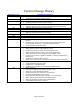
Version Change History Document Version 3.93 3.92 3.91 3.90 3.89 3.88 3.87 3.86 3.85 3.84 3.83 • • • • • • • • • • • • • • • • 3.82 3.81 3.80 • • • • • • • • • • • • • • • • • • • • • • Description of Change(s) Added HP Barcode Scanner H-Series section 6.9.7.1 Prerequisites. Updated HP Line Display T-Series section. Updated section 6.4.4.2 Dual Cash Drawer Connection. Added HP Engage Go Mobile System and peripherals. Updated section 6.9.6 Image Capture Testing.
1 Introduction This document contains setup and quick testing information for HP Point of Sale (POS) peripherals and systems. Note: All HP Point of Sale (POS) peripherals are not available worldwide; please check with the HP reseller in your area for the available HP peripherals. 2 2.1.1 General Information Where to obtain the latest software for the HP POS Peripherals The latest released versions of software for the HP peripherals are available on the HP.COM web site.
4 Default OPOS Logical Names for HP Point of Sale Peripherals Device Default OPOS Logical Name HP Barcode Scanners HP Engage One 2D Barcode Scanner N3680-HP HP Engage One W 2D Barcode Scanner N3680-HP HP Engage Go Mobile System Barcode Scanner N660X-HP HP Imaging Barcode Scanner HPImagerScanner HP Linear Barcode Scanner HPLinearScanner HP Linear Barcode Scanner II HPLinearScanner HP Presentation Barcode Scanner HPPresentationScanner HP Retail Integrated Barcode Scanner HPIntegratedImagingBarcodeScanner H
HP Engage One W Top Mount 2x20 CFD HP Graphical POS Pole Display HP POS Pole Display HP Retail Integrated 2x20 Complex HP Retail Integrated 2x20 Display HP Retail RP7 VFD Customer Display HP RP9 2x20 LCD Top Mount without Arm HP RP9 Integrated 2x20 Display Btm w/Arm HP RP9 Integrated 2x20 Display Top w/Arm HPTD620Display HPPOSCCPoleDisplay HP POS Pole Display HPLCM960Display HPLCM220Display HPPOSCCPoleDisplay HPLM940Display HPLM940Display HPLM940Display HP MSRs HP ap5000 Magnetic Stripe Reader HP Engage G
5 OPOS Logical Device Name Utility The “HP OPOS Logical Device Name Utility” can be used to obtain the logical name of the OPOS drivers that are installed on the unit. The utility also provides the ability to change the OPOS logical name of the device. For the HP Point of Sale (POS) peripherals the utility also provides the ability to set the HP POS peripherals back to the factory default logical name.
o The “Device” tab in the utility reflects the OPOS drivers that are installed on the unit: o The “Refresh” button will refresh the device tree information: Page 15 of 522
o The “Show Default” button will allow one to set the HP peripherals to default factory name (see section 5 for more details): o The “Setting” tab in the utility reflects the registry location where the utility obtains the data that is displayed in the “device” tab: Page 16 of 522
o The “About” tab provides version information on the utility: o Either the “Exit” or “X” can be used to exit the application: Page 17 of 522
5.2 Obtain OPOS Logical Device Name(s) The following section describes how to obtain the OPOS logical device names that are installed on the unit. 5.2.1 Overview Steps The following is an overview of the steps to obtain the OPOS device name: 1. Open the utility. 2. Select the “Device” tab. 3. Expand the device tree for which you would like to obtain the OPOS device name. 5.2.2 Detailed Steps The following are detailed steps to obtain the OPOS device name: 1. Open the utility. 2. Select the “Device” tab.
3. Expand the device tree for which you would like to obtain the OPOS device name. o The following shows the “LineDisplay” tree expanded. The OPOS device name that is installed on the unit in this example is “HP POS Pole Display” Note: This is an example and may not reflect what is installed on your system. Your system may have more or less items installed. o The following shows the “MSR” tree expanded.
o The following shows the “POSPrinter” tree expanded. The OPOS device names that are installed on the unit in this example are “A776 / A794 / A799”: Note: This is an example and may not reflect what is installed on your system. Your system may have more or less items installed. o The following shows the “Scale” tree expanded which is a non-HP branded device.
5.3 Change OPOS Logical Device Name(s) The following section describes how to change the OPOS logical device names that are installed on the unit. 5.3.1 Overview Steps The following is an overview of the steps to change the OPOS device name: 1. Once the utility is opened select the “Device” tab. 2. Expand the device tree for which you would like to change the OPOS device name. 3. Select the device name; it should also appear in the “Edit Device Name” box. 4.
2. Expand the device tree for which you would like to change the OPOS device name. 3. Select the device name.
4. Enter/edit the OPOS name that you wish the selected device to be: 5.
After clicking the “SAVE” button you will be prompted to confirm that you want to make the changes, click on “YES” to make the changes: Once you have confirmed you want to make the changes the utility will refresh and close all the device trees.
5.4 Set HP branded device to factory default OPOS logical name The following section describes how to set the HP branded peripherals back to the factory default OPOS logical name. Note: By default this utility will only set the HP branded peripherals to the factory default name if selected. Please refer to section 6 for non-HP branded peripherals being added to INI file. 5.4.1 Overview Steps The following is an overview of the steps to change the OPOS device name: 1.
2. Select the device you wish to change back to the factory default name: 3.
The following shows the utility GUI after the “Show Defaults” button has been clicked: Page 27 of 522
4. Select the category of the device that you would like to set back to the factory default OPOS name.
5. Select the device of the device that you would like to set back to the factory default OPOS name.
o Once you have selected the device the factory default name will be entered into the “Default Logical Name” box.
o To save the default name click on the “Set Default” button: 6.
5.4.3 Default INI File When the “HP OPOS Logical Device Name” utility is opened a default INI file is created if it does not already exist. The “default.ini” file is used by the utility for the default names of the HP peripherals in the default drop box section of the utility. If the “default.ini” is modified for non-HP peripherals those should appear in the default drop box section of the utility. 5.4.
The following is showing the default INI file which reflects the above screen capture: If the “default.ini” file is modified to add a device (i.e.
When the utility is opened with the updated default.INI file it will look like: Note: If the OPOS drivers for the device are re-installed this may change the device name. The “HP OPOS Logical Device Name” utility does not install any OPOS drivers or any registry entries to the OPOS drivers.
6 Peripherals Connection and Software Installation The USB peripherals should be installed after the Windows operating system has been unbundled. Installing one peripheral at a time will help determine which peripheral has an issue if a peripheral does not function. By installing one peripheral at a time, Windows may install the native drivers with very little user interaction needed during the native driver installation.
6.1.1 Key lock position The following shows the key lock position for the HP cash drawers: Heavy Duty Cash Drawer Lock Option 1 (Locked Closed) 2 (Online) 3 (Manual Open) 4 (Locked Open) Description Prevents the cash drawer from being opened by electrical signal from the printer. Operation of the cash drawer is driven electronically by the printer. Allow manual access to the contents of the cash drawer. Prevents the cash drawer being latched closed.
6.1.2 Connection The cash drawer is attached to the back of the printer or integrated cash drawer port using a RJ12 type connector (the smaller connector). The smaller connector connects to the back of the printer, the larger connector connects to the bottom of the cash drawer.
The following is the back of the printer with the cover open: Close-up of cash drawer connector on the back of the printer: Page 38 of 522
6.1.3 Windows Drivers for the Cash Drawer Drivers There are no Windows drivers for the cash drawer. The cash drawer is controlled by the printer Windows mini-drivers thus the printer drivers need to be installed to electronically open the cash drawer. Confirm that the cash drawer is connected to the back of the printer via the cash drawer cable. 6.1.
6.1.5 Dual Cash Drawer Connection To use dual Cash Drawers, a Y-Adapter (PN: CD-D1D2) and 2nd Drawer cable (PN: CD001B) are required. Connect the Cash Drawers to the HP Cash Drawer Port using the diagram below: 1st Drawer** 2nd Drawer Y-Adapter CD-001A CD-001B CD-D1D2 ** This cable is shipped with the HP Cash Drawer.
6.1.6 OPOS Drivers for the Cash Drawer The OPOS drivers for the cash drawer are included in the printer OPOS driver installation. Confirm that the cash drawer is connected to the back of the printer via the cash drawer cable. 6.1.7 OPOS Test Applet for the Cash Drawer The cash drawer may be tested with one of two utilities. The first utility will only test the cash drawer; the second utility will allow you to test both the cash drawer and the printer. 6.1.7.
3. Select correct device name for the cash drawer to be tested. 4. Click the Open button. 5. Click the Enable button. 6. Click the Open Drawer button and the cash drawer should open. The GUI should also show status that the cash drawer is open.
7. Close the cash drawer and the GUI should give the status that the cash drawer is closed. 8. Exit the test utility by clicking on DISABLE/CLOSE/CLOSE FORM and then click on EXIT.
6.1.8 JPOS Drivers for the Cash Drawer The JPOS drivers are included in the HP factory image and are also available from HP.COM. The following is an overview of the steps to test the cash drawer followed by detailed steps: 1. Open Printer/Cash Drawer/MICR Unit Test Application. • C:\xxxxx\Point of Sale\Receipt Printer\JPOS POS Printer\HPJPOSPrinter.bat. 2. Click on the CashDrawer tab. 3. Select the “CashDrawer” model in the Profile dropdown box: 4. Click the Open button. 5. Click the Claim button. 6.
3. Select the “CashDrawer” model in the Profile dropdown box: 4. Click the Open button. 5. Click the Claim button.
6. Click the Enable button. Note: Depending on the JPOS driver version (prior to March 2012 release) when you click on the “OpenDrawer” button the cash drawer should pop open. When the “Timeout” value set to “0”, if the cash drawer is not closed within 10 seconds a “JPOSEXCEPTION CAUGHT” error message will appear, this is OK since the cash drawer is open. 7. To exit the application: o Click the Disable button.” o Click the Release button. o Click the Close button.
6.2 HP Cash Drawer Port 6.2.1 Connection The HP Cash Drawer Port is included on the following devices, thus not removable (can be disabled). If your device is not listed below, see section HP Integrated Cash Drawer Port. The Cash Drawer is attached to the HP Cash Drawer Port using a RJ12 type connector. Note: The HP Cash Drawer Port is to be used in conjunction with a Cash Drawer that has a 24VDC solenoid. Refer to the Hardware Reference Guide included in the HP factory image and available from HP.
6.2.3 Dual Cash Drawers To use dual Cash Drawers, a Y-Adapter (PN: CD-D1D2) and 2nd Drawer cable (PN: CD001B) are required. Connect the Cash Drawers to the HP Cash Drawer Port using the diagram below: 1st Drawer** 2nd Drawer Y-Adapter CD-001A CD-001B CD-D1D2 ** This cable is shipped with the HP Cash Drawer.
6.2.4 Windows Drivers No Windows Drivers are needed. The HP Cash Drawer Port is natively supported by the OS. 6.2.5 OPOS HP Cash Drawer Port OPOS is included in the HP factory image and can be found on HP.COM. 6.2.6 JPOS HP Cash Drawer Port JPOS is included in the HP factory image and can be found on HP.COM. 6.2.7 Testing the Cash Drawer 6.2.7.
2. Click the OPOS Open button. 3. Choose from the available options by checking the checkboxes. 4. Click the OPOS Claim button. 5. Click the OPOS Enable button.
6. Click the Get Status button. The Cash Drawer status will be displayed. 7. Click the Open Drawer button. The Cash Drawer should open.
8. Click the Get Status button. The Cash Drawer status will be displayed. 9. Close the Cash Drawer. 10. Click the OPOS Disable button. 11. Click the OPOS Release button. 12. Click the OPOS Close button. 13. Exit HP CD Port Two Drawer OPOS Test Application.
6.2.7.2 Testing in JPOS Steps 1. Open HP CDPORT JavaPOS Tester. • C:\\HP\HP Cash Drawer Port JPOS\service\HPCDPORT_JPOSTester\HPCDPORT_JPOSTester.bat 2. Click the Open button. 3. Click the Claim button. 4. Check the EnableDevice checkbox. The Cash Drawer status will be displayed. 5. Click the OpenDrawer button. The Cash Drawer should open and the Cash Drawer status will be displayed. 6. Close the Cash Drawer. 7. Uncheck the EnableDevice checkbox. 8. Click the Release button. 9.
3. Click the Claim button. 4. Check the EnableDevice checkbox. The Cash Drawer status will be displayed. 5. Click the OpenDrawer button. The Cash Drawer should open and the Cash Drawer status will be displayed. 6. Close the Cash Drawer. 7. Uncheck the EnableDevice checkbox. 8. Click the Release button. 9. Click the Close button. 10. Exit HP CDPORT JavaPOS Tester.
6.3 HP Integrated Cash Drawer Port 6.3.1 Connection The HP Integrated Cash Drawer Port is included on the following devices, thus not removable (can be disabled). If your device is not listed below, see section HP Cash Drawer Port. The Cash Drawer is attached to the HP Integrated Cash Drawer Port using a RJ12 type connector. Note: The integrated cash drawer port is to be used in conjunction with a cash drawer that has a 24VDC solenoid.
6.3.2 • HP rp5800 and HP rp5810: • HP RP7 Model 7100/7800: Pinout The integrated cash drawer port supports a 24VDC solenoid cash drawer (RJ12 connector). The following is the pin out for the integrated cash drawer port.
6.3.3 Dual Cash Drawers To use dual Cash Drawers, a Y-Adapter (PN: CD-D1D2) and 2nd Drawer cable (PN: CD001B) are required. Connect the Cash Drawers to the HP Cash Drawer Port using the diagram below: 1st Drawer** 2nd Drawer Y-Adapter CD-001A CD-001B CD-D1D2 ** This cable is shipped with the HP Cash Drawer.
6.3.4 Drivers and utilities for the Integrated Cash Drawer Port The Integrated Cash Drawer may be tested with several utilities which are described in the following sections. 6.3.5 OPOS Drivers for the Integrated Cash Drawer Port The Integrated Cash Drawer Port OPOS drivers are included in the HP factory image and are also available from HP.COM. 6.3.5.1 HP Integrated OPOS Cash Drawer Utility The following is an overview of the steps to test the cash drawer followed by detailed steps: 1.
12. Click the “Open” button. 13. Click the “Claim” button. 14. Click the “Enable” button. The “Drawer Status” will display a status event for the cash drawer current state. 15. Click the “Open Drawer” button to open the cash drawer. The “Drawer Status” should reflect the cash drawer open state.
16. Close the cash drawer. The “Drawer Status” should reflect the cash drawer closed state. 17. To exit the utility: • Click the “Disable” button. • Click the “Release” button. • Click the “Close” button. • Click the “X” in the upper right-hand corner of the utility window(s).
6.3.5.2 OPOS Cash Drawer and Printer Utility This utility is included in the HP Factory image and can be obtained by downloading and installing the “HP USB Receipt Printer OPOS Test Application” Softpaq. The following is an overview of the steps to test the cash drawer followed by detailed steps: 1. Open OPOS Test Application. • C:\xxxxx\Point of Sale\Receipt Printer\OPOS Test Utility\OPOS_Test_Application.exe. 2. Click the CashDrawer button. 3.
3. Under Device To Open, select the device name for the cash drawer to be tested. 4. Click the Open button. 5. Click the Enable button. 6. Click the Open Drawer button to open the cash drawer. A StatusUpdateEvent should be displayed reflecting the cash drawer open state.
7. Close the cash drawer. A StatusUpdateEvent should be displayed reflecting the cash drawer closed state. 8. To exit the utility: • Click the Disable button. • Click the Close button. • Click the “X” in the upper righthand corner of the utility window.
Page 64 of 522
6.3.6 JPOS Drivers for the Integrated Cash Drawer Port The Integrated Cash Drawer Port JPOS drivers are included in the HP factory image and are also available from HP.COM. 6.3.6.1 JPOS Test Applet for the Integrated Cash Drawer Port The following is an overview of the steps to test the cash drawer followed by detailed steps: 1. Open HP Integrated JavaPOS Cash Drawer Utility. • C:\\Hewlett-Packard\HP Integrated Cash Drawer\JavaPOS\service\HPJPosCDUtility.exe. 2.
4. Click the “Enable” button. The “Drawer Status” will display a status event for the cash drawer current state. 5. Click the “Open Drawer” button to open the cash drawer. The “Drawer Status” should reflect the cash drawer open state. 6. Close the cash drawer. The “Drawer Status” should reflect the cash drawer closed state.
7. To exit the utility: • Click the “Disable” button. • Click the “Release” button. • Click the “Close” button. • Click the “X” in the upper right-hand corner of the utility window(s).
6.4 HP USB Cash Drawer 6.4.1 Connection The HP USB Cash Drawer may be plugged into any free USB port. One may plug the USB cash drawer into the powered USB port in the 5v connection; when plugged into a powered USB port the power portion of USB port is not utilized. 6.4.2 Drivers and utilities for the HP USB Cash Drawer The HP USB cash drawer may be tested with several utilities which are described in the following sections of the guide. 6.4.
3. Click on “Open Cash Drawer” button and the drawer should open and provide status. 4. Close the cash drawer.
5. Click the “X” button in the upper right corner to exit the utility.
6.4.4 OPOS Drivers for the HP USB Cash Drawer The HP USB Cash Drawer Port drivers are included in the HP factory image and are also available from HP.COM. 6.4.4.1 OPOS Cash Drawer and Printer Utility The following is an overview of the steps to test the cash drawer followed by detailed steps: Steps 1. Open OPOS Test Application. • C:\xxxxx\Point of Sale\Cash Drawer\USB Cash Drawer\Cash Drawer OPOS Test Utility\OPOS_Test_Application.exe. 2. Click the CashDrawer button. 3.
3. Select the correct device name for the cash drawer to be tested. The OPOS name for the HP USB cash drawer is: HPUSBCashDrawer-1. 4. Click the Open button. 5. Click the Enable button. 6. Click the Open Drawer button and the cash drawer should open. The GUI should also show status that the cash drawer is open.
7. Close the cash drawer and the GUI should give the status that the cash drawer is closed. 8. Click the Disable button, then Close button, then Close Form button, and then the “X” button on the top right to exit.
6.4.4.2 Dual Cash Drawer Connection For dual USB cash drawers, attach a second HP USB cash drawer to USB connection. The following is overview of the steps to add a second USB cash drawer followed by detailed steps for OPOS to recognize both cash drawers. Steps 1. Open HP OPOS USB Cash Drawer Utility. • C:\\HP\HP USB Cash DrawerOPOS\HPCDUtility.exe 2. Click the Add New HP USB Cash Drawer Device icon (or select Add Device from the Edit menu). 3. Click the Next button. 4.
3. Click the Next button. 4. Click the Health Check (Interactive) button. 5. Click the OK button. The cash drawer should open with the GUI indicating Cash Drawer open was successful.
6. Click the OK button. 7. Click the Cancel button to quit the Health Check. 8. Click the Finish button. 9. Exit HP OPOS USB Cash Drawer Utility.
6.4.5 JPOS Drivers for the HP USB Cash Drawer The HP USB Cash Drawer Port drivers are included in the HP factory image and are also available from HP.COM. 6.4.5.1 JPOS Test Applet for the USB Cash Drawer Port 1. Open JavaPOStester. • C:\xxxxx\Point of Sale\Cash Drawer\USB Cash Drawer\USB Cash Drawer JPOS\HPJPOSUSBCashDrawer\POSTest.bat. 2. Click the CashDrawer tab. 3. Select the proper device from the dropdown menu. 4. Click the Open button. 5. Click the Claim button. 6. Check the Device enabled checkbox.
2. Click the CashDrawer tab. 3. Select the proper device from the dropdown menu.
4. Click the Open button. 5. Click the Claim button.
6. Check the Device enabled checkbox. The drawer status will appear in the GUI. 7. Click the Open Cash Drawer button to open the selected cash drawer.
8. After drawer has opened successfully, close the drawer and click on the Release button. Note: Multiple STATUS UPDATE EVENTs with the same status may appear in the GUI.
9. Click the Close button. 10. Click the Exit button to close the test application.
6.5 HP Receipt Printer C-Series 6.5.1 Connection The HP receipt printer is installed in the 24V powered USB port on the HP POS system. The following show the back of the various HP POS units showing where the 24V power USB port is located. Refer to the Hardware Reference Guide included in the HP factory image and available from HP.
HP RP7 Model 7100 and HP RP7 Model 7800: HP ap5000: HP rp3000: Page 84 of 522
HP rp5700: HP rp5800 and HP rp5810: HP rp5000: Note: The 24V powered USB port and cable are keyed differently than 12V powered USB connector, as well as the color.
6.5.
The single station printer with serial interface requires two cables: power (hosiden) and serial data cable.
6.5.3 NATIVE mode Please note that PRINTER CLASS is the default mode of the printer; please see next section for more details on PRINTER CLASS. On the HP Point of Sale units with Windows operating system, the drivers for Windows device manager are installed on the image from the HP factory. When the printer is attached to the unit via the powered USB connection, Windows will load the drivers for the HP POS printer.
HP Hybrid Printer in Native mode Page 89 of 522
6.5.4 PRINTER CLASS Mode When the printer is in PRINTER CLASS mode, the Microsoft Windows native drivers are loaded by operating system for device manager. PRINTER CLASS mode must be used when the POS application does not use OPOS driver to communicate the receipt printer.
6.5.5 COMM CLASS Mode If the correct boot and flash firmware level are present on the printer (see table below) the printer can be put into COMM CLASS. When the printer is in COMM CLASS mode a virtual COM port is assigned to the printer USB interface for application that only communicate to the printer via serial port. One can look in Windows Device Manager → PORTS to determine the virtual com port that Windows assigned to the virtual printer COM port.
The following is showing what appears in Windows Device Manager after the driver has been loaded for the printer in COMM CLASS mode: Page 92 of 522
6.5.6 USB Mode Selector Utility If the proper level of firmware is present on the receipt printer the USB MODE SELECTOR utility can be used to switch the printer between NATIVE / PRINTER / COMM Class mode. The HP USB receipt printer must be attached to the desktop computer and all Microsoft Windows device drivers must be loaded (no yellow exclamation marks in Device Manager) in order for the utility to work correctly. The following is an overview of the steps to use the USB Mode Selector Utility: 1.
6.5.6.1 Set printer to NATIVE mode The following are the steps to switch the printer to NATIVE MODE (native mode is only supported in XP based operating system – WePOS / POSReady 2009 / Windows XP Professional): Note: Native Mode option is no longer available starting with version 1.0.0.9 of the utility. 1. Select NATIVE MODE in the GUI. 2. Click on the CHANGE button. 3. Once the printer has loaded the drivers and changed modes, the GUI will change the printer mode status to NATIVE USB.
6.5.6.2 Set printer to PRINTER CLASS mode (default) The following are the steps to switch the printer to PRINTER CLASS MODE (printer default): 1. Select PRINTER CLASS in the GUI. 2. Click on the CHANGE button. 3. Once the printer has loaded the drivers and changed modes, the GUI will change the printer mode status to PRINTER CLASS USB.
6.5.6.3 Set printer to COMM CLASS mode (virtual serial port) The following are the steps to switch the printer to COMM CLASS MODE: 1. Select COMM CLASS in the GUI. 2. Click on the CHANGE button. 3. Once the printer has loaded the drivers, close and re-open the utility in order to have the utility display the virtual COMM PORT that was assigned by Windows.
One may also look in Windows Device Manager → PORTS to see the virtual COMM PORT assignment. 6.5.7 Serial Printer The serial version of the printer will not show as a unique device in Windows device manager. Ensure that the serial port in device manager is present and does not have yellow bang.
6.5.8 Windows Drivers for the Receipt Printer Drivers The printer has two modes: NATIVE and PRINTER CLASS. mode of the printer. PRINTER CLASS is the default The PRINTER CLASS mode is used with POS application that use Windows printer driver to print, they do not use OPOS to communicate to the printer. Note: The Windows mini-drivers and the OPOS drivers cannot be set to the same COM port. 6.5.8.1 Windows Printer Driver (USB) for v1.0.
2. Select your printer model that appear on the screen. 3. Select the USBxxx (Virtual Printer Port of USB) printer port from the drop menu (towards the bottom of the drop down menu).
When the selections are made, the selection should be similar to the following screen: In order to make the printer the default printer select the option “Set as default printer”.
If one wishes to print a test page, select the option “Print test page” in the GUI. 4. Click “OK” to install the printer driver and a test print out will occur if the option was selected.
6.5.8.2 Windows Printer Driver (Serial) for v1.0.5 for POSReady 2009 The following is an overview of the steps to test the receipt printer followed by detailed steps: 1. Print out the diagnostic form on the printer in order to obtain the baud rate the printer is set to. 2. Go into the communication port properties to change the Windows baud rate to the printer is set to on the diagnostics form (previous step) and flow control to “Hardware” for port that the printer is attached. 3.
Note: The baud rate may be different than the screen shot shown above. 3. Start the setup program for the Windows mini-drivers by double clicking on “HP_Mini_Drivers.BAT” file and click “OK” One can open the “HP_Mini_Drivers.BAT” file from the “C:\xxxxx\Point of Sale\Receipt Printer\Windows Receipt Printer Drivers” folder and double click on the “HP_Mini_Drivers.BAT” file. The following is the GUI that one will see when the “HPSETUP.
4. Select your printer model that appears on the screen. 5. Select the COM (serial) port that the printer is attached to.
When the selections are made, the selection should be similar to the following screen: In order to make the printer the default printer, select the option “Set as default printer”: Page 105 of 522
To print a small test page, select the option “Print test page”: 6. Click “OK” to install the printer driver and a test printout will occur if the option was selected.
6.5.8.3 Windows Printer Driver (Ethernet) for v1.0.5 for POSReady 2009 The following is an overview of the steps to test the receipt printer followed by detailed steps: 1. Print out the diagnostic form on the printer in order to obtain the IP Address and the RAW TCPIP Port information. 2. Go to Control Panel – Devices and Printers and select “Add a printer”. 3. Select “Add a local printer”. Do not select the network option. 4. Select “Create a new port” option. 5.
The following is partial A799II – Diagnostics Form printout showing the IP address and Port info: Note: The default IP address is 192.0.0.192.
2. Go to Control Panel – Devices and Printers and select “Add a printer”.
3. Select “Add a local printer”. Do not select the network option. 4. Select “Create a new port” option.
5. Select “Standard TCP / IP Port” option and click on the next button. 6. Enter the IP Address that is printed on the diagnostics form and click on the “Next” button. Note: The IP Address is an example, yours will differ.
7. On the “Additional port information required” GUI select “Standard Generic Network Card” and click on “Next” and click the “Finish” button.
8. When the “Install the printer driver” GUI appears select “Have Disk” option. 9. When the “Install From Disk” option appears browse to the location where the drivers are located and select the “OEMPRINT.INF” file and click “Open” For the HP factory image the location are: 32Bit Image C:\ xxxxx\Point of Sale\Receipt Printer\Windows Receipt Printer Drivers\32Bit\ For the A798 printer use the A794 folder. 10.
11. On the “Print Sharing” GUI select the option “Do not share this printer” and click on the “Next” button. 12. On the “Print Test Page” GUI select the “No” option and click on the “Next” button. The configuration is not complete is the reason for selecting no.
13. Click on the “Finish” button. 14. Go to the “Devices and Printers” and right click on the printer that was just installed and select “Properties”.
15. Select the “Ports” tab. 16. Highlight the port for the printer that was installed and select “Configure Port”.
17. Go to the “Raw Settings” section on the “Configure Standard TCP/IP Port monitor” GUI. In the “Port Number” section enter 9001 (double check the diagnostics form to confirm 9001 is on the “Raw TCPIP Port” and click OK. 18. Close the printer properties GUI screen. 19. Go to the “Devices and Printers” and right click on the printer that was just installed and select “Properties”. 20. Click on “Print Test Page” and printout should occur.
6.5.8.4 Windows Printer Driver (USB) for v1.0.0 – 1.0.3 The following is an overview of the steps to test the receipt printer followed by detailed steps: 1. Start the setup program for the Windows mini-drivers by opening the “HPSETUP.EXE” program and click “OK” on the main GUI (graphical user interface). 2. Select if running 32-Bit or 64-Bit operating system. 3. Select the printer model that you wish to install. 4. Select the printer driver option that you wish to install from the drop down menu. 5.
2. Select if running 32-Bit or 64-Bit operating system. 3. Select the printer model that you wish to install.
4. Select the printer driver option that you wish to install from the drop down menu. • The HP A7xx CD#1 and HP A7x CD#2 versions generate a pulse to open cash drawer 1 or 2, respectively after each document. The HP A7xx COMP version does not send the reset command at the start of every document. Note: “xx” is the complete model number of the printer, (i.e. A794 / A799 / A776). 5. Select the USBxxx (Virtual Printer Port of USB) printer port from the drop menu (towards the bottom of the drop down menu).
When the selections are made, the selection should be similar to the following screen: In order to make the printer the default printer select the option “Set as default printer”.
If one wishes to print a very small test page, select the option “Print test page” in the GUI. 6. Click “OK” to install the printer driver and a small test print out will occur if the option was selected. Note: If the option was selected to install the printer driver with “NoCut” when “Print Test Page” is selected during the driver install process, the test print out will print and it will cut the receipt paper.
6.5.8.5 Windows Printer Driver (Serial) for v1.0.0 – 1.0.3 The following is an overview of the steps to test the receipt printer followed by detailed steps: 1. Print out the diagnostic form on the printer in order to obtain the baud rate the printer is set to. 2. Go into the communication port properties to change the Windows baud rate to the printer is set to on the diagnostics form (previous step) and flow control to “Hardware” for port that the printer is attached. 3.
Note: The baud rate may be different than the screen shot shown above. 3. Start the setup program for the Windows mini-drivers by double clicking on “HPSETUP.EXE” file and click “OK”. One can open the “HPSETUP.EXE” file from the start menu or go to the “C:\xxxxx\Point of Sale\Receipt Printer\Windows Receipt Printer Drivers” folder. The following is the GUI that one will see when the “HPSETUP.
4. Select the printer model that you wish to install. 5. Select the printer driver option that you wish to install from the drop down menu. • The HP A7xx CD#1 and HP A7x CD#2 versions generate a pulse to open cash drawer 1 or 2, respectively after each document. The HP A7xx COMP version does not send the reset command at the start of every document. Note: “xx” is the complete model number of the printer, (i.e. A794 / A799 / A776).
6. Select the COM (serial) port the printer is attached to.
In order to make the printer the default printer select the option “Set as default printer”. If one wishes to print a very small test page, select the option “Print test page” in the GUI. 7. Click “OK” to install the printer driver and a small test print out will occur if the option was selected. Note: If the option was selected to install the printer driver with “NoCut” when “Print Test Page” is selected during the driver install process, the test print out will print and it will cut the receipt paper.
6.5.8.6 Test Receipt Printer in Windows Environment (non-OPOS) In addition to the test option during the Windows mini-drivers installation, once the printer driver is loaded one may use notepad (or WordPad) to confirm the drivers are loaded and communicating to the printer. Type in a sentence or two in Notepad/WordPad and select the option to print; what was type should appear on the print out. If the Windows mini-driver with “CD#1” was selected, the cash drawer should also open.
Or one can set all the margins to zero “0”. By setting the margins to zero “0”, WordPad to automatically sets the margins to the minimum setting.
The following is a partial example of appears on the print out using the file that is included with mini-drivers: Page 130 of 522
6.5.8.7 Windows Printer Driver (USB) for v1.0.3 and later for Windows 7 / 8.1 / 10 The following is an overview of the steps to test the receipt printer followed by detailed steps: 1. Go to Control Panel – Devices and Printers and select “Add a printer”. 2. Select “Add a local printer”. 3. Select “Use an existing port” option and “USB00x (Virtual printer port for USB)” 4. When the “Install the printer driver” GUI appears select “Have Disk” option and click on “Next”. 5.
2. Select “Add a local printer”. 3.
4. When the “Install the printer driver” GUI appears select “Have Disk” option and click on “Next”. 5. When the “Install From Disk” option appears browse to the location where the drivers are located and select the “HP_Receipt_OEM” or “HP_Receipt_OEM64” file and click “Open” For the HP factory image the locations are: 32Bit Image C:\xxxxx\Point of Sale\Receipt Printer\Windows Receipt Printer Drivers\32Bit_MiniDrivers\Receipt 64Bit Image C:\xxxxx\Point of Sale\Receipt Printer\Windows Receipt Printer Drivers
6. When you are back to the “Install the printer Driver” GUI “HP Receipt” printer will appear, click on the “Next” button. 7. Enter a printer name or use the default of “HP Receipt” and click on the “Next” button.
8. Once the printer drivers is installed click on the “Finish” button. Prior to clicking on the “Finish” button one can click “Print a test page”.
6.5.8.8 Windows Printer Driver (Serial) for v1.0.3 and later for Windows 7 / 8.1 / 10 The following is an overview of the steps to test the receipt printer followed by detailed steps: 1. Print out the diagnostic form on the printer in order to obtain the baud rate the printer is set to. 2. Go into the communication port properties to change the Windows baud rate to the printer is set to on the diagnostics form (previous step) and flow control to “Hardware” for port that the printer is attached. 3.
3. Go to Control Panel – Devices and Printers and select “Add a printer”. 4. Select “Add a local printer”. 5. Select “Use an existing port” option and select the COM port the printer is attached to.
6. When the “Install the printer driver” GUI appears select “Have Disk” option and click on “Next”. Note: The above COM port maybe differ than your setting. 7. When the “Install the printer driver” GUI appears select “Have Disk” option and click on “Next”.
8. When the “Install From Disk” option appears browse to the location where the drivers are located and select the “HP_Receipt_OEM” or “HP_Receipt_OEM64” file and click “Open”. For the HP factory image the locations are: 32Bit Image C:\xxxxx\Point of Sale\Receipt Printer\Windows Receipt Printer Drivers\32Bit_MiniDrivers\Receipt 64Bit Image C:\xxxxx\Point of Sale\Receipt Printer\Windows Receipt Printer Drivers\64Bit_MiniDrivers\Receipt 9.
10. Enter a printer name or use the default of “HP Receipt” and click on the “Next” button. 11. Once the printer drivers is installed click on the “Finish” button. Prior to clicking on the “Finish” button one can click “Print a test page”.
6.5.8.9 Windows Printer Driver (Ethernet) for v1.0.3 & later for Windows 7 / 8.1 / 10 The following is an overview of the steps to test the receipt printer followed by detailed steps: 1. Print out the diagnostic form on the printer in order to obtain the IP Address and the RAW TCPIP Port information. 2. Go to Control Panel – Devices and Printers and select “Add a printer”. 3. Select “Add a local printer”. Do not select the network option. 4. Select “Create a new port” option. 5.
The following is partial A799II – Diagnostics Form printout showing the IP address and Port info: Note: The default IP address is 192.0.0.192.
2. Go to Control Panel – Devices and Printers and select “Add a printer”. 3. Select “Add a local printer”. Do not select the network option. 4. Select “Create a new port” option.
5. Select “Standard TCP / IP Port” option and click on the next button. 6. Uncheck “Query the printer and automatically select the driver to use” 7. Enter the IP Address that is printed on the diagnostics form and click on the “Next” button. Note: The IP Address above is an example.
After click the “Next” button “Detecting TCP/IP Port” box will appear. 8. On the “Additional port information required” GUI select “Standard Generic Network Card” and click on “Next”.
9. When the “Install the printer driver” GUI appears select “Have Disk” option and click on “Next”. 10. When the “Install From Disk” option appears browse to the location where the drivers are located and select the “HP_Receipt_OEM” or “HP_Receipt_OEM64” file and click “Open” For the HP factory image the locations are: 32Bit Image C:\xxxxx\Point of Sale\Receipt Printer\Windows Receipt Printer Drivers\32Bit_MiniDrivers\Receipt 64Bit Image C:\xxxxx\Point of Sale\Receipt Printer\Windows Receipt Printer Driver
11. When you are back to the “Install the printer Driver” GUI “HP Receipt” printer will appear, click on the “Next” button. 12. Enter a printer name or use the default of “HP Receipt” and click on the “Next” button.
13. Once the printer drivers is installed click on the “Finish” button. Do not click on the “Print a test page” button since the configuration is not complete. 14. Go to the “Devices and Printers” and right click on the printer that was just installed and select “Printer Properties”. 15. Select the “Ports” tab. 16.
17. Go to the “Raw Settings” section on the “Configure Standard TCP/IP Port monitor” GUI. In the “Port Number” section enter 9001 (double check the diagnostics form to confirm 9001 is on the “Raw TCPIP Port” and click OK. 18. Close the printer properties GUI screen. 19. Go to the “Devices and Printers” and right click on the printer that was just installed and select “Printer Properties”. 20. Click on “Print Test Page” and printout should occur.
6.5.8.10 Windows Printer Driver Options for v1.0.3 and later for Windows 7 / 8.1 / 10 The options for full cut / partial cut / cash drawer / cash drawer selection are not located in the receipt printer advanced options. 1. Go the Printer and Faxes section in Windows. 2. Select the HP Receipt Printer and right click to go to the Printing Preferences. 3. Click on the Printing Preferences button. 4. Click on the Advance button.
5. Selection the desired option in the Printer Features section.
Page 152 of 522
6.5.9 Knife Cut Commands Some POS application that use the Windows mini-drivers request the knife cut command so the application can perform a cut after something is printed (i.e. No Sale). The following the decimal commands: The partial knife cut leaves 5mm (0.20 inch) of paper on the left edge.
6.5.10 OPOS Drivers for the Receipt Printer The receipt printer OPOS drivers are included in the HP factory image and are also available from HP.COM. Note: If you are using the serial printer, one will need to uninstall the OPOS drivers and then re-install the OPOS driver (see details below of installation). HP OPOS driver version 1.0.1.34 (or later) supports the serial receipt printer. OPOS driver 1.0.1.
4. Select the Emulation Mode of the printer being installed (HP H300 Printer is Generation II). If HP A776/A776II Printer was selected, choose the appropriate Imager option.
5. Select YES or NO to install OPOS Control Objects. If “NO” is selected, ensure that the standalone CCO package is installed prior to using the OPOS test program or a Point Of Sale application. The CCO installation package can be found in the HP factory image or HP.COM. 6. Select USB Communications as the Connection Method.
7. Select the USB connection method (printer class is the default). 8. For the remaining options, defaults can be selected until the installation is complete.
6.5.10.2 OPOS Installation – Serial Port The following is an overview of the steps to install the receipt printer followed by detailed steps: 1. Print out the diagnostic form on the printer in order to obtain the baud rate the printer is set to. 2. Open OPOS Support For HP Printers. • C:\xxxxx\Point of Sale\Receipt Printer\POS Printer OPOS\setup.exe. 3. Select only the printer(s) that need to be installed. 4. Select the Emulation Mode of the printer being installed (HP H300 Printer is Generation II). 5.
4. Select the Emulation Mode of the printer being installed (HP H300 Printer is Generation II). If HP A776/A776II Printer was selected, choose the appropriate Imager option.
5. Select YES or NO to install OPOS Control Objects. If “NO” is selected, ensure that the standalone CCO package is installed prior to using the OPOS test program or a Point Of Sale application. The CCO installation package can be found in the HP factory image or HP.COM. 6. Select Serial Communications as the Connection Method.
7. Select the COM (serial) port that the printer is attached. 8. Refer to the diagnostics form that was printed in step 1 for the baud rate of the printer and select the Baudrate for Serial Communications. Note: The baud rate may be different than that shown above.
9. Select the Parity for Serial Communications. 10. Select the Flow Control for Serial Communications. 11. For the remaining options, defaults can be selected until the installation is complete.
6.5.10.3 OPOS Installation - Ethernet In the HP factory image the OPOS driver is installed in USB mode. Later in this section are the steps to change the OPOS driver from USB mode to Ethernet mode; see “OPOS – Ethernet IPS Address (Registry)” section. These steps will need to be used even if the printer driver Ethernet option is selected during installation in order to get the correct IP address into the registry.
3. Select Generation II Printer for Emulation Mode. 4. Select YES or NO to install OPOS Control Objects. If “NO” is selected, ensure that the standalone CCO package is installed prior to using the OPOS test program or a Point Of Sale application. The CCO installation package can be found in the HP factory image or HP.COM.
5. Select Ethernet Communications (A799 II) as the Connection Method. 6. For the remaining options, defaults can be selected until the installation is complete.
6.5.10.4 OPOS – Ethernet IP Address (Registry) 1. Plug the printer into the network and have power to the printer. 2. Run a diagnostic printout and obtain the printer IP address from the printout. Steps to obtain a diagnostics printout. a) Be sure paper is in the printer (1). b) Open the receipt cover (2). c) Press and hold the paper feed button (3). d) Close the receipt cover (2).
3. Go to the “Ethernet” folder that is found in the OPOS package folder. Then go to the “Registry Files” folder within the package. 4. In 32Bit operating system using Notepad (or text editor) modify the “Printer_32Ethernet.REG” file with the Port / Address (IP Address) that is on the diagnostics printout that was obtained earlier. In 64Bit operating system using Notepad (or text editor) modify the “Printer_64Ethernet.
6. Double click on the registry file to update the registry. One of the following messages will appear asking for confirmation. Click the YES button to allow the registry to be updated. After clicking the YES button, one of the following confirmation screens will appear indicating that the update was successful. Click OK to complete the process. If you are not sure if you are on 32Bit or 64Bit operating system: • Modify the “Printer_32Ethernet.
6.5.10.5 OPOS – Ethernet IP Address (GUI) 1. Plug the printer into the network and have power to the printer. 2. Run a diagnostic printout and obtain the printer IP address from the printout. Steps to obtain a diagnostics printout. e) Be sure paper is in the printer (1). f) Open the receipt cover (2). g) Press and hold the paper feed button (3). h) Close the receipt cover (2).
3. Go to the “Ethernet” folder that is found in the OPOS package folder. Then go to the “GUI” folder within the package. 4. Open the Receipt Printer IP Address utility via the batch file (if one wants to open the GUI directly ensure it is done with administrate privileges). Enter the IP Address for the receipt printer in the GUI. 5. Press OK on the dialog box that appears that shows the IP address that was entered.
6. Close the Receipt Printer IP Address utility. Button Blank Box OK Clear IP Address Exit Description Where the IP Address for the receipt printer is entered. Will update the Windows registry with the information entered in the box. Note: If you are not sure of the address of the printer or what this is, contact your IT administrator. Will clear the entry in the box. Will close and exit the utility.
6.5.10.6 OPOS Test Applet for the Receipt Printer - Receipt Printer and Cash Drawer Utility The following is overview of the steps to test the receipt printer followed by detailed steps: 1. Open OPOS Test Application. • C:\xxxxx\Point of Sale\Receipt Printer\OPOS Test Utility\OPOS_Test_Application.exe. 2. Click the Printer button 3. Select printer from the drop down menu. 4. Click “Open Printer” 5. Click “Claim Printer” 6. Click “Enable Printer” 7.
3. Select printer from the drop down menu. 4. Click “Open Printer”, in the main GUI one will receive status. If successful the status will say SUCCESS. If failure occurs at this point make sure the printer is plugged in and the LED is on solid and the OPOS drivers are installed on the computer.
5. Click “Claim Printer”, in the main GUI one will receive status. If successful the status will say SUCCESS. If failure occurs at this point confirm that the CCO 1.9 (or later) files are installed on this unit. If the CCO files need to be installed, they can be found in the HP factory image (C:\xxxxx\Point of Sale\Common Control Object (CCO)) and are also available from HP.COM. 6. Click “Enable Printer”, in the main GUI one will receive status.
7. What is typed in the sample text to print box will be sent to the printer to be printed on the receipt printer when one clicks on “PRINT” button.
8. Click “Feed” to advance the paper 10 line feed that is in the receipt printer. In the GUI success status should appear after the “Feed” button is successful: 9. Click “Cut” to cut the receipt.
10. To exit the application clicking on “DISABLE PRINTER” / “Release Printer” / “Close Printer” and “Close Form”.
11. To close the main application GUI, click on EXIT.
6.5.10.7 Rotate Left Testing The following is overview of the steps to test the receipt printer followed by detailed steps: 1. Open OPOS Test Application. • C:\xxxxx\Point of Sale\Receipt Printer\OPOS Test Utility\OPOS_Test_Application.exe. 2. Click the Printer button. 3. Select your printer from the drop down menu. 4. Click “Open Printer” 5. Click “Claim Printer” 6. Click “Enable Printer” 7. Click on “Print” button to confirm that the printer is printing. 8. Click on “Rotate Left” button. 9.
3. Select your printer from the drop down menu. 4. Click “Open Printer”, in the main GUI one will receive status. If successful the status will say SUCCESS. If failure occurs at this point make sure the printer is plugged in and the LED is on solid and the OPOS drivers are installed on the computer. 5. Click “Claim Printer”, in the main GUI one will receive status. If successful the status will say SUCCESS. If failure occurs at this point confirm that the CCO 1.9 (or later) files are installed.
6. Click “Enable Printer”, in the main GUI one will receive status. If successful, the status will say SUCCESS as shown below for “Open Printer” / “Claim Printer” / Enable Printer”.
7. Click on “Print” button to confirm that the printer is printing.
8. Click on “Rotate Left” button.
9. Click on “PRINT” button.
10. Click on “Rotate Normal” button.
11. To exit the application clicking on “DISABLE PRINTER” / “Release Printer” / “Close Printer” and “Close Form”.
12. To close the main application GUI, click on EXIT.
6.5.10.8 Bitmap / Barcode Testing 1. The following are the steps to test bitmap or barcode on the receipt printer: a. If you have not enabled the printer, please complete steps in the previous section. b.
Bitmap i. There are three test bitmaps (GRID.BMP / HP.BMP / TEST.BMP) that can be used. These bitmaps are located in the “C:\xxxxx\Point of Sale\Receipt Printer\OPOS Test Utility. ii. Select the bitmap alignment (left / center / right). iii. Select “I’ll set it” option. Set it to 500 in the Bitmap Width. iv. Click on “PrintBitmap” button. The printer should have printed the selected bitmap. v. Click on “CLOSE FORM” button.
vi. Click on DISABLE PRINTER / RELEASE PRINTER / CLOSE PRINTER and CLOSE FORM button.
Barcode i. Select the bar code alignment (left / center / right). ii. Select “Human Readable Characters” (Above / Below / None). iii. Select Bar Code Width (Small / Medium / Large) iv. Select Interleaved 2 of 5 in the drop down box. v. Type in numerical value for the barcode. vi. Click on “PrintBarCode”. The printer should have printed the barcode. vii. Click on “Close Form” button. viii. Click on “Disable Printer” button. ix. Click on “Release Printer” button. x. Click on “Close Printer” button.
xi. Click on “Close Form” button.
6.5.10.9 Receipt Printer and Cash Drawer Utility – Cash Drawer Testing The following is an overview of the steps to test the cash drawer followed by detailed steps: 1. Open OPOS Test Application. • C:\xxxxx\Point of Sale\Receipt Printer\OPOS Test Utility\OPOS_Test_Application.exe. 2. Click the CashDrawer button. 3. Select correct device name for the cash drawer to be tested. 4. Click the Open button. 5. Click the Enable button. 6. Click “OPEN Drawer” and the cash drawer should open.
3. Select correct device name for the cash drawer to be tested. 4. Click the Open button. 5. Click the Enable button. 6. Click “OPEN Drawer” and the cash drawer should open. The GUI should also show status that the cash drawer is open.
7. Close the cash drawer and the GUI should give the status that the cash drawer is closed. 8. Exit the test utility the clicking on DISABLE/CLOSE/CLOSE FORM and then click on EXIT.
Page 196 of 522
6.5.11 OPOS Test Applet for the MICR The following is overview of the steps to test the receipt printer followed by detailed steps: 1. Open OPOS Test Application. • C:\xxxxx\Point of Sale\Receipt Printer\OPOS Test Utility\OPOS_Test_Application.exe. 2. Click the MICR button. 3. Click the Open MICR button. 4. Click the Claim MICR button. 5. Click the Enable MICR button. 6. Insert the check in the front of the printer until the front LED comes on. 7. Click the Begin Insertion button. 8.
3. Click the Open MICR button. The main GUI should show SUCCESS. 4. Click the Claim MICR button. The main GUI should show SUCCESS.
5. Click the Enable MICR button. The main GUI should show SUCCESS. If one receives a message stating “NO Hardware” and the LED is blinking on the printer, please ensure that there is not a paper jam. 6. Insert the check in the front of the printer until the front LED comes on.
7. Click the Begin Insertion button. 8. Click the End Insertion button. At this point the printer will perform the MICR operation; the document should come out the front and then will be returned back to the bottom portion of the printer. 9. Click the Enable Data Event button. The data from the MICR should appear in the bottom of the GUI.
Note in the above example the actual number have been replaced the “x”. 10. Click the Begin Removal button and remove the check from the printer when it has been ejected. 11. Click the End Removal button.
12. To exit the application, click the Disable MICR button, the Release MICR button, and the Close MICR button. 13. Click the Close Form button.
6.5.12 OPOS Test Applet for the CheckScan Note: The check scanner feature is only available on the HP Hybrid printer that has imaging capabilities. The following is an image of the the HP Hybrid printer model with imaging capabilities: The following is overview of the steps to test the receipt printer followed by detailed steps: 1. Open OPOS Test Application. • C:\xxxxx\Point of Sale\Receipt Printer\OPOS Test Utility\OPOS_Test_Application.exe. 2. Click the CheckScan button. 3. Click the Open button. 4.
3. Click the Open button.
4. Click the Claim button.
5. Click the Enable button.
6. Click the BeginInsertion button. You should hear a click noise from the printer.
7. Insert the check face up in the front of the printer until the front LED comes on. 8. Click the EndInsertion button. At this point the printer will perform the “CheckScan” operation; the document should come out the front and then will be returned back to the bottom portion of the printer.
9. Click the Enable Data Event button.
10. Click the RetrieveImage button.
11. Click on “SAVE AS” under “FILE” to save the image that was captured. Save the file with “TIF” extension. After the file is save in the message box will state “File Written”.
Page 212 of 522
12. Click the BeginRemoval button. 13. Click the EndRemoval button.
14. Close the “CheckScan” by clicking on DISABLE / RELEASE / CLOSE button in this order. 15. Close the form.
6.5.13 Receipt Printer Cash Drawer Signal 6.5.13.1 Cash Drawer Signal The cash drawer is attached to the back of the printer using an RJ12 or similar connector (the smaller connector). On HP cash drawers, this connector sends a HIGH signal from the printer to open the cash drawer. The HIGH signal is the default setting for the HP OPOS receipt printer drivers installation. However, there are other cash drawers that may be using an opposite LOW signal to open the cash drawer.
6.5.14 JPOS Drivers for the Receipt Printer Drivers – Serial Port Setting If you are using the serial version of the receipt printer, the entry in the CONFIG.XML must be edited to reflect the COM (serial) port to which the printer is attached. The CONFIG.XML from HP is located in the “..\Receipt Printer JPOS\JPOS\jpos\res” folder, the location will most likely be in a different location for your point of sale application.
If the printer is attached to COM1, one needs to comment out the USB entry / enable the COM port entry and enter the correct COM port. The following is an example of what the changes would look like: Note: Make sure the other communication parameters (Baudrate / DataBits, etc) all match your Windows setting and printer.
6.5.15 JPOS Drivers for the Receipt Printer Drivers – Ethernet If you are using the Ethernet version of the receipt printer, the entry in the CONFIG.XML must be edited to reflect the Ethernet port and IP Address to which the printer is attached. The CONFIG.XML from HP is located in the “..\Receipt Printer JPOS\JPOS\jpos\res” folder; the location will most likely be different location for you point of sale application.
3. Go the “Receipt Printer JPOS\JPOS\jpos\res” folder. 4. Using Notepad (or text editor) modify the A799 section in the “CONFIG.XML” file. The following items will need to be modified: • PortName for Ether will need to be uncommented out. o Remove”!--“ (two dashes) from the beginning of the line and ”--“ (two dashes) towards the end of the line. • IPAddress that is on the diagnostics printout will need to entered in the CONFIG.XML file.
Page 220 of 522
6.5.16 JPOS Drivers for the Receipt Printer Drivers The JPOS drivers are included in the HP factory image (C:\xxxxx\Point of Sale\Receipt Printer\JPOS POS Printer) and are also available from HP.COM. The following is an overview of the steps to test the receipt printer followed by detailed steps: 1. Open Printer/Cash Drawer/MICR Unit Test Application. • C:\xxxxx\Point of Sale\Receipt Printer\JPOS POS Printer\HPJPOSPrinter.bat. 2. Select the printer model in the profile drop down box. 3.
2. Select the printer model in the profile drop down box: 3. Click the Open button. 4. Click the Claim button. 5. Click the Enable button.
6. Click on the Simple Printing tab. 7. Type the text you wish to print into the Print Data area.
8. Click the PrintNormal button. The receipt printer should print the text. Note: In order to see the text you will need to press the line feed button on the printer unless you added several carriage returns to your text.
6.5.17 JPOS Drivers for the Receipt Printer Drivers - CheckScanner Note: The check scanner feature is only available on the HP Hybrid printer that has imaging capabilities. The following is image of the model of the HP Hybrid printer with imaging capabilities: The JPOS drivers are included in the HP factory image (C:\xxxxx\Point of Sale\Receipt Printer\JPOS POS Printer) and are also available from HP.COM. The following is an overview of the steps to test the receipt printer followed by detailed steps: 1.
Detailed Steps 1. Open Printer/Cash Drawer/MICR Unit Test Application. • C:\xxxxx\Point of Sale\Receipt Printer\JPOS POS Printer\HPJPOSPrinter.bat. 2. After a few seconds the JPOS test utility GUI will appear as shown below. 3. Click on the CheckScanner tab.
4. Click the Open button. 5. Click the Claim button. 6. Click the Enable button. After all three buttons on clicked the screen will look similar to the following screen capture: 7. Insert a piece of paper face up that you wish to capture an image of during this test in the front of the printer until the LED comes on. The paper should be inserted face up in the slip portion of the printer. Click the Begin button in the left TransactionPrint box.
8. Click the End button in the left TransactionPrint box. The printer will make some noise and move the paper through the imager. After a few seconds a status will appear in the status box. In the open CMD box, it will note the amount of time it took to for the image transfer.
9. Check the Data Events Enabled checkbox. 10. Click the Retrievelmage button. After the button is pressed the status will be updated and some information will be filled about the image.
11. Click the DisplayImage button to view the image that was scanned. When the DisplayImage button is pressed another box will appear with the image, which will allow one to save the image if they wish.
12. To Exit the application one needs to “Disable/Release/Close” the printer and then click on the “X” to close the application. 13. The piece of paper that was inserted in step 7 can be removed from the imager portion of the printer by pulling on the paper; there will be slight force needed when the paper is pulled.
6.5.18 JPOS Drivers for the Receipt Printer Drivers - MICR The JPOS drivers are included in the HP factory image (C:\xxxxx\Point of Sale\Receipt Printer\JPOS POS Printer) and are also available from HP.COM. The following is an overview of the steps to test the receipt printer followed by detailed steps: 1. Open Printer/Cash Drawer/MICR Unit Test Application. • C:\xxxxx\Point of Sale\Receipt Printer\JPOS POS Printer\HPJPOSPrinter.bat. 2. Click on the MICR tab. 3. Click the Open button. 4.
3. Click on the MICR tab: 4. Click the Open button. 5. Click the Claim button. 6. Click on the Enable button.
7. Click on the MICR Read tab: 8. Slide the check facing up into the MICR until the LED comes on. 9. Click the Enable Data Events button.
10. Click the Begin button in the Insertion box. 11. Click the End button in the Insertion box. When End is clicked, the printer will engage and read the MICR information on the check.
The data that was read will appear in the MICR Data box (“x” represents where data that is read would appear). 12. To exit the application, need to disable/release and close the MICR from the MICR tab.
The following shows the device has been released and is available for other applications after the “Disable / Release / Close” buttons have been clicked: 13. The piece of paper that was inserted in step 8 can be removed from the imager portion of the printer by pulling on the paper; there will be slight force needed when the paper is pulled.
6.5.19 JPOS Drivers for the Receipt Printer Drivers – Slip Printing The JPOS drivers are included in the HP factory image (C:\xxxxx\Point of Sale\Receipt Printer\JPOS POS Printer) and are also available from HP.COM. The following is an overview of the steps to test the receipt printer followed by detailed steps: 1. Open Printer/Cash Drawer/MICR Unit Test Application. • C:\xxxxx\Point of Sale\Receipt Printer\JPOS POS Printer\HPJPOSPrinter.bat. 2.
3. Click the Open button. 4. Click the Claim button. 5. Click the Enable button. After all three buttons are clicked the screen will look similar to the following screen capture. 6. Select the Slip option in the Printer Station box.
7. Click on the Slip tab. 8. Click the Begin button in the Insertion box. Slide the paper in the front of the printer until it comes out from the top.
9. Click the End button in the Insertion box. The paper may move down and the LED light should stay on indicating paper is in the slip. 10. Click on the Simple Printing tab.
11. Type some text in the Print Data area; this is the text that should print on the receipt printer and click the PrintNormal button. 12. Click on the Slip tab.
13. Click the Begin button in the Removal box. Once the paper comes out from the top remove the paper from the printer. 14. Click the End button in the Removal box. 15. To exit the application, disable/release and close the printer from the “POSPrinter” tab.
The following shows the printer has been released and is available for other applications after “Disable / Release / Close” button have been clicked: Page 244 of 522
6.5.20 JPOS Drivers for the Receipt Printer Drivers – Barcode Testing Detailed Steps 1. Open Printer/Cash Drawer/MICR Unit Test Application. • C:\xxxxx\Point of Sale\Receipt Printer\JPOS POS Printer\HPJPOSPrinter.bat. 2. Select the printer from the dropdown menu in the POSPrinter tab. 3. Click the Open button. 4. Click the Claim button.
5. Click the Enable button. After all three buttons are clicked the screen will look similar to the following screen capture: 6. Click on the “Bitmaps/Barcode” tab. In the “Print BarCode” section, fill in the appropriate values for the barcode.
UPCA Page 247 of 522
UPCE Page 248 of 522
JAN 8 Page 249 of 522
JAN13 Page 250 of 522
ITF Page 251 of 522
Codabar Page 252 of 522
Code 39 Page 253 of 522
Code 93 Page 254 of 522
Code 128 Page 255 of 522
Code 128 Page 256 of 522
Code 128 Parsed Page 257 of 522
PDF 417 Page 258 of 522
QR Code Page 259 of 522
6.5.21 JPOS Drivers for the Cash Drawer Drivers The JPOS drivers are included in the HP factory image and are also available from HP.COM. The following is an overview of the steps to test the receipt printer followed by detailed steps: 1. Open Printer/Cash Drawer/MICR Unit Test Application. • C:\xxxxx\Point of Sale\Receipt Printer\JPOS POS Printer\HPJPOSPrinter.bat. 2. Click on the CashDrawer tab. 3. Select the CashDrawer model in the Profile dropdown box: 4. Click the Open button. 5.
3. Select the CashDrawer model in the Profile dropdown box. 4. Click the Open button. 5. Click the Claim button. 6. Click the Enable button.
Note: Depending on the JPOS driver version (prior to March 2012 release) when you click on the “OpenDrawer” button the cash drawer should pop open. When the “Timeout” value set to “0”, if the cash drawer is not closed within 10 seconds a “JPOSEXCEPTION CAUGHT” error message will appear, this is OK since the cash drawer is open. 7. To exit the application: o Click the Disable button. o Click the Release button. o Click the Close button. o Click the “X” in the upper righthand corner of the application.
6.5.22 HP Font Utility (ASIAN Font Download) – Single Station (A799 with 4MG) Printer The single station printer can have an additional font downloaded to the printer via the HP Font Download utility. The English font will always be present in the printer even when an additional font is downloaded to the printer. The following fonts can be downloaded to the printer: Chinese / Kanji / Korean. Note: This is only needs to be performed on the single station printer that has 4MB of memory.
2. Click on the “Allocate Memory for Fonts” button. The status box will indicate that the allocation process has been completed. 3. Click on the language that you would like to download to the printer. This process can take up to 10 minutes to complete; during the download process the LED on the printer will blink. When the process has completed downloading, the font the status box will indicate that is it complete.
Page 265 of 522
Page 266 of 522
4. Click on “Print Sample/Diagnostics” to confirm you are able to get a print out after the font download. Note that the print out will be in English. 5. Click on “Exit” to leave and close the application.
6.6 HP ap5000 MSR (Magnetic Stripe Reader) 6.6.1 Connection The MSR on the HP ap5000 system is integrated into the system which is connected internally via serial interface; default is COM4. There is no user connection required for this device. ap5000 MSR Port Baud Rate COM4 19200 Data Bit Parity Stop Bit Flow Control 6.6.2 8 None 1 None Windows Drivers for the HP ap5000 MSR Windows operating system supports serial port COM4, so no extra drivers are needed to be installed. 6.6.
3. When the “Test Mode” has been selected the COM port will appear and in the GUI title bar “(Test Mode)” will appear. At this point when one swipes a card in the ap5000 MSR, the data will appear in the test utility. 4. To exit the application: a. Click “Test Mode” so “(Test Mode)” does not appear in the title of the GUI. b. Click on “Exit” to close test applet. Detailed Steps 1. Start the non-OPOS test utility from Windows start menu. 2.
3. When the “Test Mode” has been selected the COM port will appear and in the GUI title bar “(Test Mode)” will appear. At this point when one swipes a card in the ap5000 MSR, the data will appear in the test utility.
4. To exit the application: a. Click “Test Mode” so “(Test Mode)” does not appear in the title of the GUI. b. Click on “Exit” to close test applet.
6.6.4.2 Testing HP ap5000 MSR in OPOS mode The following is overview of the steps to test the ap5000 MSR followed by detailed steps: 1. Start the OPOS test utility from Windows start menu. 2. Click on the “OPEN” button to start the test, should receive “Open Success” status message. 3. When one swipes a valid card in the ap5000 MSR data should appear in the test utility. The “x” represent will be replaced by the data that is read from the card that is swiped. 4. To exit the application: a.
2. Click on the “OPEN” button to start the test, should receive “Open Success” status message. 3. When one swipes a valid card in the ap5000 MSR data should appear in the test utility. The “x” represent will be replaced by the data that is read from the card that is swiped.
4. To exit the application: a. Click “CLOSE” button. b. Click on “X” in the upper right hand corner to close the test applet.
6.6.5 JPOS Drivers for the HP ap5000 MSR The HP ap5000 JPOS drivers are included in the HP factory image (C:\xxxxx\Point of Sale\MSR HP ap5000\ap5000 MSR JPOS) and are also available from HP.COM. The following is overview of the steps to test the ap5000 MSR followed by detailed steps: 1. Start the JPOS test utility either using the link in the START MENU or by opening the POSTEST.BAT file locate in the JPOS folder in the ap5000 MSR folder. 2. Click on the “MSR” tab. 3. After clicking on the “MSR” tab. 4.
2. Click on the “MSR” tab: 3.
The logical name of the device is “HPap5000MSR” which should appear in the logical name field. If another name is present, change the logical name to “HPap5000MSR”. If one clicks on the “Configured Device” tab, the names for the device will appear that will be used in the test utility. 4. Click on the “OPEN” button. 5. Click on the “CLAIM” button.
6. Check the “DATA EVENT ENABLED” so there is a check box. 7. Check the “DEVICE ENABLED” so there is a check box. 8. Swipe a credit card and text should appear in the field. Depending on the type of card there may or may not be information displayed in all of the track field.
9. Click on “RELEASE” / “CLOSE” and then click “EXIT” to exit the JPOS test utility.
6.
6.7.1 Connection The MSR may be plugged into any free USB port, including powered USB ports. If a powered USB port is used, the powered portion is just not utilized. For All-in-One systems, the MSR may be plugged into any designated free USB port on the display. 6.7.2 Interfaces The MSR supports the following interfaces: • • USB HID USB HID Keyboard (default) Both interfaces are supported under OPOS. 6.7.
Changing Dual Head setting: Click the Change Basic Reader Settings button, make a selection, and click the Send to MSR button.
Changing Track Separator and Terminator: Click the Change Basic Reader Settings button, click on the Track Settings tab, either make a selection from Non-Printable Char dropdown menu or type in the separator character to be used, and click the Send to MSR button.
6.7.4 Windows Drivers The MSR is natively supported by the Windows operating system as a Human Interface Device (HID). If during the driver installation Windows displays the new hardware wizard, the user needs to accept the defaults that appear during the hardware wizard GUI (for the first screen you may select the no option) and the native drivers will be loaded. Please refer to “If prompted for native driver location (New Hardware Wizard)” section.
6.7.5 OPOS Drivers for the MSR The MSR OPOS drivers included in the HP factory image and are also available from HP.COM. 6.7.6 Testing MSR 6.7.6.1 Testing MSR in USB HID Keyboard interface Open Microsoft Notepad and swipe a card. If data appears as in the example below, this confirms that the MSR interface is USB HID Keyboard. If nothing appears in Notepad, the MSR interface is likely set to USB HID.
2. Select the MSR OPOS logical name from the drop down menu that you wish to test. 3. Click “OPEN” button, if successful will receive and OPOS_SUCCESS message.
4. Click on “CLAIM” button, if successful will receive and OPOS_SUCCESS message. 5. Click on “Device Enabled” so there is a check in the box, if successful will receive and OPOS_SUCCESS message.
6. Swipe a credit card. Click on “TRACK DATA” tab to see the data that was read.
Page 289 of 522
In order to test another card swipe it is recommended to click on the “ClearInputProperties” and “ClearInput” button to remove all the data that appears in the test application. 7. To close the MSR OPOS test application click on RELEASE / CLOSE / EXIT buttons in the order stated.
6.7.7 JPOS Drivers for the MSR The JPOS drivers are included in the HP factory image and are also available from HP.COM. The “MSR Keyboard Base Driver” must also be installed on the unit either via the standalone package or via the OPOS drivers installed on the unit. The following is overview of the steps to test the MSR followed by detailed steps: 1. Open JavaPOStester located in one of the paths below: • C:\\HP\HP MSR I-Series JPOS\POStest\POStest.bat. • C:\xxxxx\Point of Sale\MS
2. Click on the “Configured Device” tab to obtain the device names. 3. Click on the “MSR” tab.
4. Enter the Logical Name for the MSR. (Note: This item is case sensitive). 5. Click on the “OPEN” button; the MSR will beep several times.
6. Click on the “CLAIM” button; the MSR will beep several times. 7. Check the “DATA EVENT ENABLED” and “DEVICE ENABLED” checkboxes.
8. Swipe a credit card and text should appear in the field. Depending on the type of card there may or may not be information displayed in all of the track fields. 9. Click the “RELEASE” button.
10. Click the “CLOSE” button and the click on “EXIT” to exit the JPOS test utility.
6.8 HP Barcode Scanner (Laser 1D) 6.8.1 Connection The barcode scanner may be plugged into any free USB port. One may plug the barcode scanner into the power USB port in the 5V part of USB port, when plugged in this configuration the power portion of USB port is not utilized. 6.8.2 Windows Drivers for the Barcode Scanner The HP POS scanner uses native drivers for Windows operating system.
The following is the Device Manager window after all the drivers are loaded for the HP USB Barcode Scanner (default mode): The following is the Device Manager window after all the drivers are loaded for the HP USB Barcode Scanner when it is in the OPOS mode: Page 298 of 522
6.8.3 OPOS Drivers for the Barcode Scanner There are no OPOS drivers needed for this device if the device is used in the human interface device (HID) keyboard emulation mode (default mode as shipped from the factory). If the POS application needs the OPOS drivers, the barcode OPOS drivers can be found on HP.COM. The drivers are already installed in the HP factory image. 6.8.4 Testing the Barcode Scanner 6.8.4.
Detailed Steps 1. Open the barcode scanner OPOS Test utility from Windows start menu from the “HP USB Barcode Scanner” or from the “HP Point of Sale Information” menu. 2. Click “Open Service Object” 3. Click on OK after confirming “HP_USBSCANNER” is shown for the service object name. 4. Click on “Enable Scan” 5. Scan a barcode. 6. Click on “Disable Scan” to stop scanning with the OPOS test utility. 7. Click on “Close” to close the test application.
6.8.5 JPOS Drivers for the Barcode Scanner The JPOS drivers are included in the HP factory image (C:\xxxxx\Point of Sale\Barcode Scanner\Barcode Scanner JPOS) and are also available from HP.COM. In order for the scanner to work with JPOS driver, the scanner must be programmed into the “IBM HAND-HELD USB” / OPOS mode. In order to put the scanner into this mode, scan the bard code below: IBM Hand-Held USB Note: The HIDScanWin32.DLL is copied to working JAVA directory “C:\Program Files\Java\xxxx\bin” when t
Detailed Steps 1. Start the JPOS test utility either using the link in the START MENU or by opening the POSTEST.BAT file that is located in the JPOS folder for barcode scanner (C:\xxxxx\Point of Sale\Barcode Scanner\Barcode Scanner JPOS” folder). After a few seconds the JPOS test utility GUI will appear as shown below: 2.
After clicking on the “Scanner” tab the screen should look like: The logical name of the device is “HP_USBSCANNER”. If one clicks on the “Configured Device” tab, the names for the device will appear that will be used in the test utility. 3. Click on the “OPEN” button.
4. Click on the “CLAIM” button. A check should appear next to the “CLAIMED” box. 5. Check the “DEVICE ENABLED” so there is a check box. 6. Check the “AUTO DATA EVENT ENABLE” so there is a check box. 7. Check the “DATA EVENT ENABLED” so there is a check box. 8. Check the “DECODE DATA” so there is a check box.
9. Scan a bar code: Depending on the fonts installed you may see some block character at the end of the “SCAN DATA” line, this is OK. An example 10. Click on “RELEASE” or “CLOSE” to exit the JPOS test utility.
6.
6.9.1 Connection The Barcode Scanner may be plugged into any free USB port, including powered USB ports. If a powered USB port is used, the powered portion is just not utilized. 6.9.2 Interfaces The Barcode Scanner supports the following interfaces: • • • 6.9.3 USB COM USB Composite (default) USB HID POS Configuration To change the Barcode Scanner configuration settings such as interface, there are three methods available: • • • Common configuration barcodes in this document.
HP EZConfig: • Click the CONNECTED DEVICE button to begin configuring the device.
6.9.4 Windows Drivers For USB Composite and USB HID POS interfaces, native Windows Operating System drivers are used. For USB COM interface, HP Barcode Scanner H-Series USB COM Driver is needed. It is included in the HP Factory image and can be found on HP.COM. Device Interface USB COM USB Composite (default) HP Engage Go Mobile System Barcode Scanner USB HID POS USB COM HP Engage One 2D Barcode Scanner HP Engage One W 2D Barcode Scanner 6.9.
6.9.7 Testing the Barcode Scanner 6.9.7.1 Prerequisites • Configurations with multiple H-Series Barcode Scanners in USB COM interface 1. Open OPOS Configuration Utility or JPOS Configuration Utility. • C:\\HP\HP Barcode Scanner H-Series OPOS\OPOS Configuration Utility.exe • C:\\HP\HP Barcode Scanner H-Series JPOS\JPOS Configuration Utility.exe 2. Select Edit/Remove device. 3. Click the Device type dropdown menu and select Scanner. 4.
6.9.7.2 Testing in non-OPOS/JPOS Open Microsoft Notepad and scan a barcode. The data should appear in the Notepad window. If nothing appears, confirm that the interface is set to USB Composite. 6.9.7.3 Testing in OPOS Steps 1. Open OPOS Validation Utility. • C:\\HP\HP Barcode Scanner H-Series OPOS\OPOS Validation Utility.exe 2. Click the Advanced View button. 3. Select the Device Name for your device (ex: N3680-HP). 4. Click the Open button. 5. Click the Claim button. 6.
3. Select the Device Name for your device (ex: N3680-HP). 4. Click the Open button.
5. Click the Claim button. 6. Click the Enable Device button.
7. Check the Always Enable Data Event checkbox. 8. Check the Decode Data checkbox.
9. Scan a barcode. The Scan Data will be displayed. 10. After testing is complete, click the Disable Device button.
11. Click the Release button. 12. Click the Close button. 13. Exit OPOS Validation Utility.
6.9.7.4 Testing in JPOS Steps 1. Open the JPOS Validation Utility. • C:\\HP\HP Barcode Scanner H-Series JPOS\JPOS Validation Utility.exe 2. Click the Advanced View button. 3. Select the Device Name for your device (ex: N3680-HP). 4. Click the Open button. 5. Click the Claim button. 6. Click the Enable Device button. 7. Check the Always Enable Data Event checkbox. 8. Check the Decode Data checkbox. 9. Scan a barcode. The Scan Data will be displayed. 10.
3. Select the Device Name for your device (ex: N3680-HP). 4. Click the Open button.
5. Click the Claim button. 6. Click the Enable Device button.
7. Check the Always Enable Data Event checkbox. 8. Check the Decode Data checkbox.
9. Scan a barcode. The Scan Data will be displayed. 10. After testing is complete, click the Disable Device button.
11. Click the Release button. 12. Click the Close button. 13. Exit JPOS Validation Utility.
6.
6.10.1 Connection The Barcode Scanner may be plugged into any free USB port, including powered USB ports. If a powered USB port is used, the powered portion is just not utilized. 6.10.2 Windows Drivers The HP Imaging / Linear / Presentation scanner uses native drivers for Windows operating system in USB HID-KBD mode.
The following is the Device Manager window after all the drivers are loaded for the HP RP9 Integrated Barcode Scanners in USB HID-KBD mode: Page 325 of 522
The following is the Device Manager window after all the drivers are loaded for the HP Imaging / Linear / Presentation Scanners when it is in the USB-COM mode (OPOS): Page 326 of 522
The following is the Device Manager window after all the drivers are loaded for the HP RP9 Integrated Barcode Scanners in USB-COM mode (OPOS): Page 327 of 522
The following is the Device Manager window after all the drivers are loaded for the HP RP9 Integrated Barcode Scanners in USB-Composite (default) mode: Page 328 of 522
2D Imaging Barcode Scanner with driver 3.13.xx.
HP Linear Barcode Scanner with driver 3.13.xx.
HP Presentation Scanner with driver 3.13.xx.xx Note: For Windows XP Professional / WePOS / POSReady the virtual COM port for the scanner is assigned COM20 with version 3.0.1.32. Starting with version 3.12.0.32 the virtual COM port is not fixed at COM20 but assigned the next available COM port on the system. For Vista / Windows 7 the virtual COM port is assigned the next available COM port on the system.
6.10.3 OPOS There are no OPOS drivers needed for this device if the device is used in the human interface device (HID) keyboard emulation mode. When the device is in USB-COM mode (OPOS) a Windows device driver is required. The required device drivers that support the scanner are included in the HP factory image and can be found on HP.COM. 6.10.4 JPOS The JPOS drivers are included in the HP factory image and are also available from HP.COM.
3. 4. 5. 6. Click the Open Scanner button. Click the Claim button. Click the Enable button. Click the Data Event Enable button or select Auto Data Event Enable so the status states Ready to scan a label. 7. Scan a barcode. 8. After scan is complete click the Disable button. Note: When the imaging scanner is disabled the LED on the scanner will blink to indicate that it has been disabled.
4. Click the Claim button. 5. Click the Enable button.
6. Click the Data Event Enable button or select Auto Data Event Enable so the status states Ready to scan a label. 7. Scan a barcode and the data will appear in the dialog box.
8. After scan is complete click on “Disable” button. Note: When the imaging scanner is disabled the LED on the scanner will blink to indicate that it has been disabled. When an OPOS application has been setup to use the imaging scanner in OPOS (USB COM) mode when the application is started the scanner will be enabled. When the application is exited then the imaging scanner will be disabled (LED on the scanner will blink).
9. Click the Release button. 10. Click the Close Scanner button.
11. Exit ScannerTest.
6.10.5.3 Testing in JPOS The following is overview of the steps to test the imaging barcode scanner followed by detailed steps: 1. Open JavaPOStester. • C:\xxxxx\Point of Sale\Scanner (LED_Imager)\Img_LED JPOS\HPJPOSImagingScanner.bat. 2. Click on the Scanner tab. 3. Select the proper device from the dropdown menu. 4. Click the Open button. After the imaging scanner is opened a check will appear in the “Data event enabled” box. 5. Click the Claim button. 6. Check the “Device enabled” checkbox. 7.
3. Select the proper device from the dropdown menu. 4. Click the Open button. After the imaging scanner is opened a check will appear in the “Data event enabled” box.
5. Click the Claim button. 6. Check the Device enabled checkbox.
7. Check the Decode Data checkbox. 8. Scan a barcode and the data will appear in the “Scan Data” and “Scan Data Label” boxes.
9. After scan is complete click the Release button. 10. Click the Close button. 11. Click on “Exit” to close the test application.
6.10.6 Image Capture Testing Barcode Scanners that support the Image Capture feature must be programmed into the USBCOM interface. The barcodes used to set the interface are located in the Programming Guide on HP.COM; however the USB-COM interface barcode is also provided in the steps below. The following is an overview of the steps to test the Barcode Scanner followed by detailed steps: 1. Install HP USB Scanner Configuration Utility. This may be found on HP.COM. 2.
4. Click the Search On Connection option. 5. Scan the barcode provided if the Barcode Scanner is not in USB-COM interface. 6. Select the COM port that the Barcode Scanner is attached to and click the OK button.
7. Click on the Barcode Scanner detected. The Device Values will be read. 8. Click the View Image button (eyeglass icon). When this option is selected only certain models will beep.
9. Click the Capture on Trigger option. 10. Point the Barcode Scanner at the item and press the trigger to capture an image.
6.11 HP Retail Jacket for ElitePad Barcode Scanner 6.11.1 Connection The barcode scanner is connected by installing a supported tablet into the HP Retail Jacket for ElitePad: • HP ElitePad 900 Tablet • HP ElitePad 1000 Tablet 6.11.2 Operating Modes The operating modes supported by the HP Retail Jacket for Elitepad barcode scanner are listed below along with their Windows Device Manager entries. The scanner by default is shipped in USB HID Keyboard mode; however, with scanner Firmware version 3.06.
USB HID Keyboard (default): Scanner Firmware version 3.06.068 or newer: Keyboards\HID Keyboard Device • Hardware Id: HID\VID_03F0&PID_5739 POS Barcode Scanner\POS HID Barcode scanner • Hardware Id: HID\VID_03F0&PID_5739 Universal Serial Bus controllers\USB Composite Device • Hardware Id: USB\VID_03F0&PID_5739 Scanner Firmware version older than 3.06.068: Keyboards\HID Keyboard Device • Hardware Id: HID\VID_03F0&PID_2A39 6.11.
6.11.4 Testing the scanner Sample barcodes that can be used for testing purposes are listed below.
6.11.4.1 Testing the scanner in HID-POS mode There is currently no HID-POS test app available from HP. 6.11.4.2 Testing the scanner in USB HID Keyboard mode To test the scanner in this mode open a text editor such as Microsoft Notepad, scan a barcode, and verify that a text entry is made. 6.11.4.3 Testing the scanner in USB COM mode with OPOS The following is an overview of the steps to test the scanner followed by detailed steps: 1. Open HP Mobile OPOS Scanner Test. • C:\xxxxx\Point of Sale\Scanner (M
Detailed Steps 2. Open HP Mobile OPOS Scanner Test. • C:\xxxxx\Point of Sale\Scanner (Mobile Retail Jacket)\Mobile OPOS Test Utility folder. 3. Select appropriate scanner device from the drop down box.
4. Click “Open” button. In the OUTPUT section should see OPEN SUCCESS. 5. Click “Claim” button. In the OUTPUT section should see CLAIM SUCCESS.
6. Click “Enable” button. Make sure “Always Enable Data Event” has is checked. 7. Scan a barcode and the data will appear in the dialog box.
8. After scan is complete click on “Disable” button. 9. Click “Release” button.
10. Click “Close Scanner” button. 11. Exit the application.
6.11.4.4 Testing the scanner in USB COM mode with JPOS The JPOS drivers are located in “C:\xxxxx\Point of Sale\Scanner (Mobile Retail Jacket)\ Mobile Retail Jacket Scanner JPOS” folder. The following is an overview of the steps to test the scanner followed by detailed steps: 1. Open JavaPOStester. • C:\xxxxx\Point of Sale\Scanner (Mobile Retail Jacket)\ Mobile Retail Jacket Scanner JPOS\ HPJPOSMobileScanner.bat. 2. Click on the “Scanner” tab. 3. Select the proper device from the drop down menu. 4.
2. Click on the “Scanner” tab. 3. Select the proper device from the drop down menu. 4. Click on the “OPEN” button.
5. Click on the “CLAIM” button. After clicking on the “CLAIM” button a few seconds later a check should appear next to the “Data event enabled / Device enabled / Decode data” boxes 6. Scan a barcode and the data will appear in the “Scan Data” and “Scan Data Label” boxes.
7. After scan is complete click on “Release” button. 8. Click on “Close” button. 9. Click on “Exit” to close the test application.
6.12 HP POS Keyboard 6.12.1 Connection The HP POS Keyboard may be plugged into any free USB port, including powered USB ports. If a powered USB port is used, the powered portion is just not utilized. 6.12.2 Windows Drivers The HP POS Keyboard uses native drivers for Windows operating system. Windows will load several drivers for the keyboard and touch pad.
Page 362 of 522
Page 363 of 522
The following is the Device Manager window after all the drivers are loaded for the HP POS Keyboard: 6.12.3 OPOS No OPOS drivers are needed for the keyboard. 6.12.4 JPOS No JPOS drivers are needed for the keyboard. 6.12.5 Testing the POS Keyboard Open Notepad, what is typed on the keyboard should appear in Notepad.
6.13 HP USB POS Keyboard with Magnetic Stripe Reader 6.13.1 Connection The HP USB POS Keyboard with Magnetic Stripe Reader may be plugged into any free USB port, including powered USB ports. If a powered USB port is used, the powered portion is just not utilized. 6.13.2 Windows Drivers The HP USB POS Keyboard with Magnetic Stripe Reader uses native drivers for Windows operating system. Windows will load several drivers for the keyboard and touch pad.
The following shows some of the dialog boxes that will appear while Windows is installing the drivers for this device: Page 366 of 522
Page 367 of 522
The following is the Device Manager window after all the drivers are loaded for the HP USB POS Keyboard with Magnetic Stripe Reader: Page 368 of 522
The following is the Device Manager window after all the drivers and the keyboard configuration software is installed on the unit for the HP USB POS Keyboard with Magnetic Stripe Reader: Page 369 of 522
6.13.3 Enable OPOS/JPOS for the MSR In order to use OPOS/JPOS drivers for the MSR on the HP USB POS Keyboard with Magnetic Stripe Reader one will need to enable this option. Enable MSR OPOS/JPOS The following is an overview of the steps to test the MSR followed by detailed steps: 1. Must have the HP POS Keyboard configuration utility package, run the EXE and the unit will need to be restarted after the utility has completed installation.
Page 371 of 522
4. Once the application has read the configuration you will see keyboard layout in the GUI and click on the MSR icon: 5.
6. Close the application and you will be prompted to save the setting to keyboard, click “YES”.
Page 374 of 522
6.13.4 6.13.5 6.13.6 OPOS 6.13.4.1 Keyboard No OPOS drivers are needed for the keyboard. 6.13.4.2 MSR The OPOS drivers are already installed in the HP factory image and are also available from HP.COM. JPOS 6.13.5.1 Keyboard No JPOS drivers are needed for the keyboard. 6.13.5.2 MSR The JPOS drivers are already installed in the HP factory image and are also available from HP.COM. Testing the POS Keyboard with Magnetic Stripe Reader 6.13.6.
2. Select the device name, need to select “HPKBMSR” for the MSR that is located on the HP USB POS Keyboard with Magnetic Stripe Reader. 3. Click on “BEGIN” and swipe a card. After the card is swiped data should appear in the test applet.
4. Click on “END” button to exit the test application. If one does not want to use the “AUTOMATIC” method, the following are the steps to use when manually test using the OPOS test applet. 1. Open OPOS MagneticStripeReader Demo. • C:\xxxxx\Point of Sale\Keyboard with MSR\OPOS Test Utility\oposmagnet.exe.
2. Select the device name, need to select “HPKBMSR” for the MSR that is located on the HP USB POS Keyboard with Magnetic Stripe Reader. 3. Click on “OPEN” 4.
5. Select “DataEventEnabled (R/W)” and “DeviceEnabled (R/W)” 6. Swipe a credit card and the data should appear in the test applet.
7. To exit the application: • Click on the RELEASE button. • Click on the CLOSE button. • Click on the EXIT button.
6.13.6.3 MSR JPOS The following is overview of the steps to test the MSR followed by detailed steps: 1. Open JPOS-Testsuite. • C:\xxxxx\Point of Sale\Keyboard with MSR\JPOS Test Utility\TestSuite.bat 2. Select MSR from “TEST” drop down box. 3. Click “OPEN” 4. Click “CLAIM” 5. Click on “DataEventEnabled (R/W) 6. Click on “DeviceEnabled (R/W) 7. Swipe a card. 8. Select the Release / Close / Exit buttons to exit application. Detailed Steps 1. Open JPOS-Testsuite. • C:\xxxxx\Point of Sale\Keyboard with MSR\JPO
5. Click on “DataEventEnabled (R/W) 6. Click on “DeviceEnabled (R/W) 7. Swipe a card. The data from the card should appear in the test applet. To test another card, check the “DataEventEnabled (R/W)” box and swipe. 8. To exit the application: a. Click on the RELEASE button. b. Click on the CLOSE button. c. Click on the EXIT button.
6.14 HP ap5000 VFD (Vacuum Fluorescent Display) 6.14.1 Connection The VFD on the HP ap5000 system is connected via serial interface. When attached at the HP factory the VFD is installed on COM2 as the default location. The HP ap5000 VFD can be connected either on COM2 or COM1 on the ap5000 unit; it cannot be used on COM3. If the VFD is moved to factory default location, please go to into the BIOS and enable 5V on the COM2 and disable 5V on COM1.
4. To exit the application: a. Click on “Exit” to close test applet. Detailed Steps 1. Start the Windows test utility from Windows start menu. 2. Select the COM port from the drop down box or keep the default option. The ap5000 VFD is shipped by default on COM2 from the HP factory.
3. Click on the “Test” button once “READY” appears in the status box. Once the test is complete and passes, the VFD will display “Test OK” and the test utility will provide some status information and the test results. 4. To exit the application: a. Click on “Exit” to close test applet.
6.14.4.2 Testing HP ap5000 VFD in OPOS mode The following is overview of the steps to test the ap5000 VFD followed by detailed steps: 1. Start the OPOS test utility. 2. Click on “Clear Text” to clear the text on the pole display. To display a test message on the pole, enter a message in the text box or use the default message that appear “Display this text” and click on “Display Text” 3. To blink a test message: a. Enter the test message. b. Check the “Blink” box c. Click “Display Text” button. 4.
2. Click on “Clear Text” to clear the text on the pole display. To display a test message on the pole, enter a message in the text box or use the default message that appear “Display this text” and click on “Display Text”.
3. To blink a test message: a. Enter the test message. b. Check the “Blink” box c. Click “Display Text” button.
4. To “Reverse” a test message: a. Enter the test message. b. Check the “Reverse” box c. Click “Display Text” button.
5. To display a test message on different ROW or Column: a. Enter the test message. b. From the drop down menu select the column and row where you would like the message to be displayed. c. Click “Display Text At” button. Note: In the column drop down box, the option shown are from 0 – 20 which is per the OPOS specification.
6. To cause message to scroll (test #1): a. Click on “Scrolling Text Test #1” button. The pole will scroll a message and the following message “Scrolling” appears on the VFD bottom line.
7. To cause message to scroll (test #2): a. Click on “Scrolling Text Test #2” button. The pole will scroll a message and the following message “Longer scroll message (37 characters)” appears on the VFD bottom line.
8. To display a test message with delayed character appearing: a. Enter different value (if so desired) for the delay time.
b. Click “Set CharacterDelayTime” button.
c. Enter the test message and click “Display Text” button. 9. To exit the OPOS test applet, click on the “EXIT” button or click on the “x” in the upper right corner of the test applet.
6.14.5 JPOS Drivers for the HP ap5000 VFD The JPOS drivers are already installed in the HP factory image (C:\xxxxx\Point of Sale\VFD HP ap5000\ap5000 VFD JPOS) and are also available from HP.COM. The following is an overview of the steps to test the ap5000 VFD followed by detailed steps: 1. Start the JPOS test utility either using the link in the START MENU. 2. Click on the “LineDisplay” tab. 3. Replace the “defaultLineDisplay” that appears in the logical name box with “HPap5000LineDisplay”. 4.
2.
3. The logical name of the device is “HPap5000LineDisplay”. Replace the “defaultLineDisplay” that appears in the logical name box with “HPap5000LineDisplay”. If one clicks on the “Configured Device” tab, the names for the device will appear that will be used in the test utility. 4. Click on the “OPEN” button. 5. Click on the “CLAIM” button. After clicking the “CLAIM” button, the “Device Enabled” is available.
6. Check the “DEVICE ENABLED” so there is a check box.
7. Press the “CLEAR TEXT” button. 8. Type in the test message in the “Send to line display” box and click on “Display Text” Note: On the JPOS tester utility when “INFO” button is pressed one will receive an exception. The exception error can be safely ignored; all the functions of the pole display under JPOS are working correctly. 9. Click on “RELEASE” / “CLOSE” / “EXIT” to exit the JPOS test utility.
6.14.6 Utility to change power-on message When the HP ap5000 is powered on the following message is scrolled on the display until an application takes control the pole display. There are two lines that are scrolled, the default message that is scrolled on the display is: HP ap5000 All-in-One Point of Sale System …. Thank You and Have a Nice Day …. If one wishes to change the power on message one may do so by running “HP ap5000 LineDisplay Startup Message” program.
3. Enter the message(s) that one wishes to display on the VFD. 4. From the drop down box, select the scroll speed of the message.
5. Click on the “Write to VFD” to save the message to the pole. 6. Click on “Exit” to leave the application. 6.14.6.2 Enable the VFD Default Power-On Message The following is an overview of the steps to test the power-on message utility followed by detailed steps: 1. Start the “HP ap5000 LineDisplay Startup Message” application which is available on “HP Point of Sale System Software and Documentation CD”. This utility is not included on the HP factory image. 2.
2. When the utility is opened the default HP factory message appears in the GUI. One can either click on “Write to VFD” or click on “Set to factory default” button. 3. Click on “Exit” to leave the application.
6.14.7 HP ap5000 VFD BIOS Power Setting The 5 volt power that is needed for the HP ap5000 VFD is supplied via the serial port (pin 9). When the ap5000 VFD is attached to the unit on COM2 from the HP factory and a Windows operating system is installed, the 5 volt for COM2 will be enabled natively. If the user has the need to move the VFD from COM2 to COM1 then the 5 volt for COM1 will need to be enabled by the steps outlined below. In addition, it is recommended that the 5 volt for COM2 should be disabled.
2. Open the “HP Com Port Utility.EXE” which is located on the “HP POS Software and Documentation CD” that is included in the peripherals after-market option kit. The following is the GUI that will appears when the utility is opened: 3. Select the COM port that you would like to change.. 4. Select from the two options for the COM port (Enable Power or Disable Power). When power is enabled for COM1 or COM2, 5V will be enabled. When power is enabled for COM3, 12V will be enabled.
The following is an example of the prompt screens that will appear when COM1 is enabled. The following prompt appears when the “Disable Power” option is clicked: 5. After the COM port setting is changed, restart Windows operating system for the BIOS changes to take effect. Note: The ap5000 VFD cannot be installed on COM3, it only be used on COM1 or COM2.
6.15 HP Line Display T-Series 6.15.1 Connection The HP Line Display may be plugged into any free USB port, including 5V USB ports. When plugged into a 5V USB port, the power portion of the port is not utilized. 6.15.2 Windows Drivers The HP Line Display T-Series Driver is included in the HP factory image and is also available from HP.COM. *For older device support, the Softpaq must be installed.
6.15.3 Configuration Utility The HP Line Display T-Series Configuration Utility is used to configure various settings and is only available from HP.COM. 6.15.3.1 Changing the Default Power-On Message The Default Power-On Message is configurable and will be displayed while the Line Display is powered on and idle until the POS Application takes control. Steps 1. Open HP Display Setup Utility. • C:\SWSetup\SPxxxxx\HP Display Setup Utility.exe 2. The Line Display should be detected automatically. 3.
3. Click the Obtain Setting from Display button. The Line Display will go blank and message “Device Information Successfully Retrieved.” will be received. 4. Edit the Line 1 and Line 2 messages to be displayed at Power-On.
5. Click the Download Setting to Display button to save the setting to the Line Display. The Line Display will reinitialize and message “Device information successfully downloaded.” will be received. 6. Exit HP Display Setup Utility.
6.15.4 OPOS HP Line Display T-Series OPOS is included in the HP factory image and is also available from HP.COM. 6.15.5 JPOS HP Line Display T-Series JPOS is included in the HP factory image and is also available from HP.COM. The portName COM value setting for the Line Display in jpos.xml (located in C:\\HP\HP Line Display T-Series JPOS) will need to be updated to match Device Manager and saved. 6.15.6 Testing the Line Display 6.15.6.
3. Type some text in the text box and click the Display text button. The text should appear on the Line Display. 4. Exit HP Pole Display Test.
6.15.6.1.2 HP VFD Utility Steps 1. Open HP VFD Utility. • C:\SWSetup\SPxxxxx\HP VFD Utility\\HP VFD Utility.exe. 2. The Line Display should be detected automatically. 3. Click on any of the buttons to test specific items or click on the green Play button to cycle through all buttons/tests. 4. Exit HP VFD Utility. Detailed Steps 1. Open HP VFD Utility. • C:\SWSetup\SPxxxxx\HP VFD Utility\\HP VFD Utility.exe. 2. The Line Display should be detected automatically.
3. Click on any of the buttons to test specific items. The function of each is described below. • Fixed Image → The device will display an image (similar to what is shown below).
• Scrolling Image 1 → The device will scroll an image (similar to what is shown below).
• Scrolling Image 2 → The device will scroll two different images (similar to what is shown below); one after the other.
• Scroll → The device will scroll 1234567890. • Blink → The device will blink ABCDEFGHIJ.
• Reverse Character → The device will display abcdefghij in reverse illumination. • Compound Word → The device will display Welcome in the button language (referred to as Complex Characters) on the first line and in English on the second line.
• Code page → Selecting a Codepage (language) from the dropdown menu and pressing each Codepage button will display various characters on the device. • Play → Pressing the green Play button will run all tests (including the selected Codepage) automatically. 4. Exit HP VFD Utility.
6.15.6.2 Testing in OPOS Steps 1. Open HP Line Display T-Series OPOS Demo Utility. • C:\\HP\HP Line Display T-Series OPOS\OPOS\HP Line Display T-Series OPOS Demo Utility.exe 2. Choose the device from the Select Device Name dropdown menu. 3. Click the Clear Text button to clear any text that may be on the device. 4. Enter some text into the text box. 5. Click the DisplayText button. The text should appear on the device.
Detailed Steps 1. Open HP Line Display T-Series OPOS Demo Utility. • C:\\HP\HP Line Display T-Series OPOS\OPOS\HP Line Display T-Series OPOS Demo Utility.exe 2. Choose the device from the Select Device Name dropdown menu. 3. Click the Clear Text button to clear any text that may be on the device. 4. Enter some text into the text box. 5. Click the DisplayText button. The text should appear on the device.
Additional tests available: • Display text at a specific Column and Row test: a. Specify values in the Column and Row boxes. b. Click the DisplayTextAt button. The text will appear in the location specified. • Blink test: a. Click the Blink Characters button. “!!! Blinking !!!” will be shown blinking.
• Scroll test: a. Click the Marquee Text Line 1 or Marquee Text Line 2 button. The text will scroll on the specified line.
• Display text with a different Character Set test: a. Click the Clear Text button to clear any text that may be on the device. b. Select a Character Set from the dropdown menu. c. Check the MapCharacterSet button. d. Enter some text into the text box. e. Click the DisplayText button. The text should appear on the device. 6. Exit HP Line Display T-Series OPOS Demo Utility.
6.15.6.3 Testing in JPOS Steps 1. Open JavaPOStester. • C:\\HP\HP Line Display T-Series JPOS\POStest.bat. 2. Click the Configured Devices tab and copy/note the Logical Name for the Line Display. 3. Click the LineDisplay tab. 4. Enter the Line Display Logical Name in the Logical name field. 5. Click the Open button. 6. Click the Claim button. 7. Check the Device enabled checkbox. 8. Press the Clear Text button. 9. Enter some text into the Send to line display field. 10.
2. Click the Configured Devices tab and copy/note the Logical Name for the Line Display. 3. Click the LineDisplay tab. 4. Enter the Line Display Logical Name in the Logical name field.
5. Click the Open button. 6. Click the Claim button.
7. Check the Device enabled checkbox. 8. Press the Clear Text button.
9. Enter some text into the Send to line display field. 10. Click the Display Text button. The text should appear on the device. 11. Uncheck the Device enabled checkbox. 12. Click the Release button. 13. Click the Close button. 14. Exit JavaPOSTester.
6.16 HP Fingerprint Readers 6.16.1 Connection The Fingerprint Reader may be plugged into any designated free USB port for the specific device. 6.16.2 Windows Drivers The HP Fingerprint Reader Driver is included in the HP factory image and is also available from HP.COM.
7 7.1 7.1.1 HP Touch Screen HP L5006tm Connection The HP L5006tm touch screen monitor has three (3) connections that need to be made on the back of the unit. One connector will plug into the VGA connector on the back of the unit, the second connection which is for the touch screen can be connected either via USB connector or serial connector and the third connection is for power to the monitor. The USB connection will plug into one of the free USB ports on the back of the unit.
Detailed installation instructions 1. Start the touch screen installer and select your language: Selecting default will use the language that the operating system is running. 2.
USB Connection If USB drivers are selected the installation package will search the USB ports for the monitor.
3. After the drivers are installed, please select the option to calibrate the touch screen monitor and follow the instructions on the screen.
Serial Connection If Serial Touchscreen drivers are selected you may have the installation package try to autodetect which COM port the monitor is attached to.
When the following box appears make sure that there is a check in the “Auto-detect HP Touchscreens” box.
The following screen appears that shows the com ports that were found in unit. The COM port that is selected where were the utility found the touch screen monitor. Note: The COM port listing on your unit may vary from the screen capture above. You will be asked to confirm the COM port before the drivers are installed.
Would highly recommend after the drivers are installed please restart the operating system.
The following screen is showing Windows Device Manager when the touch screen is connected to the unit via the USB cable.
The following screen is showing Windows Device Manager when the touch screen is connected to the unit via the COM port.
7.1.3 Touch Screen Alignment You will need to run the touch screen alignment program the first time you use the touch screen. There are couple methods to get to the alignment program for the touch screen. You can access this program either via the Elo ICON in the system tray or control panel. Method1: On the Elo icon in the system tray, click on the icon and select “Align ….” Option: Note: The screen capture is example, what appears in the menu may vary by driver version.
Method 2: Need to switch to classic view or Large ICON / Small ICON view in control panel in order to see the HP Touch screen option.
Select the align option; follow the on screen direction to align the touch screen: During the alignment of the touch screen you will be presented with three targets to press: Page 444 of 522
The fourth screen presented will accept the calibration that was performed: 7.1.4 OPOS Drivers for the Touch Screen No OPOS drivers are needed for the touch screen. 7.1.5 Testing the Touch Screen Touch several places on the monitor screen and the mouse cursor should be present where the monitor was touched. 7.1.6 JPOS Drivers for the Touch Screen No JPOS drivers are needed for the touch screen.
7.2 7.2.1 HP L5009tm / HP L5015tm Connection The HP L5009tm / HP L5015tm touch screen monitor has three (3) connections that need to be made on the back of the unit. One connector will plug into the VGA connector on the back of the unit, the second connection which is for the touch screen via USB connector and the third connection is for power to the monitor. The USB connection will plug into one of the free USB ports on the back of the unit.
Detailed Steps 1. Start the touch screen installer and select your language: Selecting default will use the language that the operating system is running. 2. Select the “Install APR Touchscreen Driver” option and click on the NEXT button: Note: The Serial Touchscreen Drivers option is not available for HP L5009tm / HP L5015tm.
4. Depending if the touch screen USB cable is attached to the unit or not, one of the following behaviors will be seen: a. After the drivers are installed and the HP L5009tm / HP L5015tm monitor touch screen USB cable is not attached to the unit, the installation process is complete as indicated below and the readme file may be viewed.
When one attaches the HP L5009tm / HP L5015tm monitor touch screen the APR configuration process will start, it will copy files to the hard drive (this process will take several minutes). b.
Select the option to “Calibrate HP Touchscreen monitors” and click on the “Finish” button: The calibrate option for HP L5009tm / HP L5015tm is a one point calibration, the screen during the calibration process looks like: Page 450 of 522
The following screen is showing Windows Device Manager after the HP L5009tm and HP L5015tm drivers are installed and when the touch screen is connected to the unit via the USB cable. After Windows has loaded the device drivers for the touch screen there will be an entry in “Human Interface Devices” and “Mice and other pointing devices” sections in Device Manager as shown below: HP 5009tm attached to the unit. HP 5015tm attached to the unit.
7.2.3 Touch Screen Alignment You will need to run the touch screen alignment program the first time you use the touch screen. There are couple of methods to get to the alignment program for the touch screen. You can access this program either via the HP ICON in the system tray or control panel. Method1: On the HP icon in the system tray, click on the icon and select “Align ….” Option: Note: The screen capture is example, what appears in the menu may vary by driver version.
Method 2: Need to switch to classic view or Large ICON / Small ICON view in control panel in order to see the HP Touch screen option.
Select the align option; follow the on screen direction to align the touch screen: or Page 454 of 522
During the alignment of the touch screen you will be presented with one target to press: 7.2.4 OPOS Drivers for the Touch Screen No OPOS drivers are needed for the touch screen. 7.2.5 Testing the Touch Screen Touch several places on the monitor screen and the mouse cursor should be present where the monitor was touched. 7.2.6 JPOS Drivers for the Touch Screen No JPOS drivers are needed for the touch screen.
7.3 HP ap5000 Touch Screen 7.3.1 Connection The touch screen on the HP ap5000 system is integrated into the system which is connected internally via PS/2 interface. There is no user connection required for this device. 7.3.2 Windows Drivers for the Touch Screen The HP ap5000 touch screen drivers are already installed in the HP factory image (C:\xxxxx\ap5000 Touch Drivers) and are also available from HP.COM.
3. After the drivers are installed, please select the option to calibrate the touch screen monitor and follow the instructions on the screen by opening the calibration option in the start menu or from the system tray.
Right click on the touch screen option and select “4 Points Calibration” The calibrate option for HP ap5000 is four button calibration; one button appearing in each corner of the screen. Note: When the red circle appear on the display, touch and hold the center of the red circle until it says OK.
After the calibration point has been successfully accepted an “OK” appears: Page 459 of 522
After all four points have been successfully calibrated, several screens will appear that read and write the calibration parameters.
The following screen is showing Windows Device Manager after the HP ap5000 drivers are installed: After Windows has loaded the device drivers for the touch screen there will be an HP icon in the system tray: Page 461 of 522
7.3.3 OPOS Drivers for the ap5000 Touch Screen No OPOS drivers are needed for the touch screen. 7.3.4 Testing the Touch Screen Touch several places on the monitor screen and the mouse cursor should be present where the monitor was touched. 7.3.5 JPOS Drivers for the ap5000 Touch Screen No JPOS drivers are needed for the touch screen.
7.4 HP RP7 15inch Resistive (AFD) Unit is shown down position with MSR / Biometric option. 7.4.1 Connection The 15inch resistive AFD (Associate Facing Display) is part of the base unit thus require no external cables to be connected by the user. 7.4.2 Windows Drivers for the Touch Screen For Windows 7 (32 and 64 bit) and POSReady 7 (32 and 64 bit) operating system, the touch is recognized by the operating system automatically.
2. Accept the default prompt prompts until the installation process is complete to install the drivers.
3. Once the installation is complete restart the operating system by selecting YES to the restart question or manually restart after other items installation are complete. 4. Run the calibration utility as mentioned in the touch screen calibration section.
7.4.3 Touch Screen calibration For Windows 7 (32 and 64 bit) and POSReady 7 (32 and 64 bit) operating system: 1. Click on the START button. 2. Click on CONTROL PANEL. 3. In the search box type in “Tablet PC Setting” (without the quote) and in the list of results select “Table PC Settings”. 4. On the DISPLAY tab under DISPLAY OPTION select CALIBRATE. Note: When one calibrates for the screen for the first time, the screen uses 16 different reference points.
4. Select the 9 point calibration option and follow the prompts on the screen to calibrate the touch monitor. Press the target button that appears until the next target appears. The screen shot below represent the calibration screen that will appear during the process (the “x” represent the other 8 touch point that will appear during the calibration process.
Note: The targets appear one at a time. The screen shot above represent the location where the 9 point calibration targets will appear. 5. Save the calibration setting. 7.4.4 OPOS Drivers for the Touch Screen No OPOS drivers are needed for the touch screen. 7.4.5 Testing the Touch Screen Touch several places on the monitor screen and the mouse cursor should be present where the monitor was touched. 7.4.6 JPOS Drivers for the Touch Screen No JPOS drivers are needed for the touch screen.
7.5 HP RP7 15 /17 inch Projective Capacitive AFD (Associate Facing Display) Unit is shown down position with MSR option. 7.5.1 Connection The 15 / 17 inch Projective Capacitive (PCap) AFD (Associate Facing Display) is part of the base unit thus require no external cables to be connected by the user. 7.5.2 Windows Drivers for the Touch Screen For Windows 7 (32 and 64 bit) and POSReady 7 (32 and 64 bit) operating system, the touch is recognized by the operating system automatically.
2. Click on the “OK” to start the installation process.
3. Once the installation is complete restart the operating system by selecting YES to the restart question. If one selects “NO” one will see a screen that indicates the driver was successfully installed; manually restart after other items installation are complete.
7.5.3 Touch Screen calibration For Microsoft POSReady 2009 and Windows XP Professional operating system there is no calibration needed due to the projective capacitive technology therefore there is no calibration utility for the HP RP7 15/17 inch projective capacitive touch. For Windows 7 (32 and 64 bit) and POSReady 7 (32 and 64 bit) operating system the following are the steps to open the calibration utility BUT it is not necessary for the HP RP7 15/17 inch projective capacitive touch: 1.
Once the “CONFIGURE” button is pressed on the primary monitor a screen appears that ask one to touch a box. After the box on primary monitor is touched then the similar screen appears on the secondary monitor.
After the second monitor has been touched or timeout has occurred a message indicating that the process is complete appears: Click or press on the OK button to complete the process. Note: The “Multi-mouse-daemon” information will be kept upon reboot of the operating system. If the driver is re-installed or different monitor PCAP monitor is installed on the unit the utility must be re-run in order to obtain the proper monitor information. 7.5.
4. On the DISPLAY tab under CONFGIURE click on the SETUP button. 5. Follow the prompt that appears on the screen. The following is example of the prompt that appears on the screen: 7.5.6 OPOS Drivers for the Touch Screen No OPOS drivers are needed for the touch screen. 7.5.7 Testing the Touch Screen Touch several places on the monitor screen and the mouse cursor should be present where the monitor was touched. 7.5.8 JPOS Drivers for the Touch Screen No JPOS drivers are needed for the touch screen.
7.5.9 Disable/Enable On-Screen Display (OSD) The OSD feature can be locked and unlocked. unlocked position. The monitor is shipped with the OSD menu in the To lock the OSD menu and disable the OSD controls: • Tap on the area where the OSD icons are located so that the icon become illuminated and active. • Press the “MENU” icon for approximately 10 seconds until message appears indicating the OSD is locked.
7.6 Touch Screen – HP L6015tm / L6017tm Projective Capacitive (PCap) 7.6.1 Connection Please see the documentation that comes with the monitor for connection information. 7.6.2 Windows Drivers for the Touch Screen For Windows 7 (32 and 64 bit) and POSReady 7 (32 and 64 bit) operating system, the touch is recognized by the operating system automatically.
The installation package can also be found at the following location on the HP image “C:\xxxxx\Point of Sale\HP Projective-Capacitive Touchscreen” 2. Click on the “OK” to start the installation process.
3. Once the installation is complete restart the operating system by selecting YES to the restart question. If one selects “NO” one will see a screen that indicates the driver was successfully installed; manually restart after other items installation are complete. 7.6.
7.6.4 Touch in Dual Monitor Configuration in POSReady 2009 or XP This section and the touch drivers are for Microsoft POSReady 2009 and Microsoft Windows XP operating system. In a dual touch PCAP monitor configuration, in order to have touch on both monitors one must have driver’s version 7.5.52.00 or later which can be obtained on the HP.COM website. After the drivers are obtained the following is the process to install the drivers in dual touch PCAP configuration. 1.
After the second monitor has been touched or timeout has occurred a message indicating that the process is complete appears: Click or press on the OK button to complete the process. Note: The “Multi-mouse-daemon” information will be kept upon reboot of the operating system. If the driver is re-installed or different monitor PCAP monitor is installed on the unit the utility must be re-run in order to obtain the proper monitor information.
7.6.5 Touch in Dual Monitor Setup in POSReady 7 or Windows 7 For Windows 7 (32 and 64 bit) and POSReady 7 (32 and 64 bit) operating system the following are the steps to correctly identify the touch monitors: 1. Click on the START button. 2. Click on CONTROL PANEL. 3. In the search box type in “Tablet PC Setting” (without the quote) and in the list of results select “Table PC Settings”. 4. On the DISPLAY tab under CONFGIURE click on the SETUP button. 5. Follow the prompt that appears on the screen.
7.6.9 Disable/Enable On-Screen Display (OSD) The OSD feature can be locked and unlocked. unlocked position. The monitor is shipped with the OSD menu in the To lock the OSD menu and disable the OSD controls: • Tap on the area where the OSD icons are located so that the icon become illuminated and active. • Press the “MENU” icon for approximately 10 seconds until message appears indicating the OSD is locked.
8 8.1 HP ap5000 Point of Sale System HP ap5000 10” Display 8.1.1 Connection The HP ap5000 10” display can be attached to the back of the ap5000 unit by replacing VFD. The ap5000 10” display is connected via VGA connector on the I/O panel of the unit. 8.1.2 Windows Drivers for the HP ap5000 10” display No additional drivers are necessary. The Intel video drivers that are used for the ap5000 integrated (touch screen) video are drivers that are needed to drive the 10” display. 8.1.
9 HP 7” CFD 9.1.1 Connection The HP 7” CFD can be connected to any USB port. The HP Integrated 7” CFD is designed to be attached on units and monitors that have the appropriate mounting receptacle (i.e. RP2, RP7, RP9, HP 6015tm, HP 6017tm). The HP 7” CFD supports a single resolution of 1024x600. All other display options for the HP 7” CFD can be set either through the Control Panel or the DisplayLink System Tray icon depending on the OS and DisplayLink driver version being used.
If the HP DisplayLink drivers have been installed, the following will be present in Programs and Features: Windows 10 and newer: Windows 8.
If the HP DisplayLink drivers have been installed and the HP 7” CFD is attached to the system, the following will be present in Device Manager: Windows 10 and newer: Windows 8.
9.1.3 OPOS No OPOS drivers are needed. 9.1.4 JPOS No JPOS drivers are needed. 9.1.5 Testing the HP 7” CFD Display Once the second monitor is enabled in the Windows operating system, video should appear on the HP 7” CFD display. 9.1.6 HP 7 CFD Options If the HP DisplayLink drivers have been installed, a DisplayLink icon will be present in the System Tray: Clicking this icon will bring up the available configuration options.
Q&A 9.2 General Question: What are the OPOS names for the HP Peripherals? Answer: Please refer to section OPOS Names for HP Point of Sale Peripherals for the OPOS names. Question: Where can I obtain the latest drivers? Answer: The latest drivers are posted on the HP.COM web site.
9.3 HP Cash Drawer Question: When I run the sample application I receive a message stating dependencies not correctly registered. How do I correct this? Answer: If you run the cash drawer sample application and receive the following screen, it indicates that either the CCO or the OPOS drivers are not installed and registered. Install the CCO drivers and install the printer OPOS package. After the installation is complete, please restart Windows.
9.5 HP Receipt Printer Question: When I run the sample application I receive a message stating dependencies not correctly registered. How do I correct this? Answer: If you run the cash drawer sample application and receive the following screen, it indicates that either the CCO or the OPOS drivers are not installed and registered. Install the CCO drivers and install the printer OPOS package. After the installation is complete, please restart Windows.
Question: Why do I not see an option for “USB001 (Virtual USB Port) in the Windows mini-drivers setup? Answer: In order for the port to appear, the printer must be attached to the unit AND the printer must be in printer class mode.
Question: How do I obtain the baud rate that the serial printer is set to? Answer: Perform the following steps to obtain a diagnostics printout which has the baud rate information: ▪ Open the printer cover. ▪ Pull the paper out slightly. ▪ Press and hold the form feed button on the printer. ▪ Close the printer cover. ▪ When the diagnostics form prints, let go of the form feed button. Close to the middle of the diagnostics print out is the baud rate of the printer.
Question: With the A799II printer receiving yellow bang in Windows device manager saying Cognitive TPGA795 but everything seems to work in OPOS/JPOS. How do I get rid of this yellow bang. Answer: Point to the i386 folder that is located in the Windows mini-drivers. Will need to point to the 32bit or 64bit folder depending on your operating system in order to get the correct i386 folder.
9.6 HP USB Barcode Scanner Question: I am not sure the setting of the Barcode Scanner, how can I put the scanner back to the factory default setting? Answer: You can put the scanner back to factory default setting by scanning the following bar code: Set All Defaults Question: After scanning an item, I have to press the “Enter” to accept what was scanned in my application. Answer: You can change the behavior of the scan so that a carriage return is also transmitted after an item is scanned.
Question: I need to use OPOS drivers with my application for the scanner, where can I obtain them from? Answer: The OPOS drivers for the scanner may be obtained from the HP web site under the software/driver section for the product.
IBM Hand-Held USB Question: The volume of the scanner is loud for my environment, how can I lower the volume on the scanner? Answer: There are three volume setting for the scanner low / medium (default) / high. Scan one of the bar code below to set the volume on the scanner: Low Medium (Default) High Question: When I scan something in notepad it appears to garbage in non-English language? Answer: The barcode scanner USB country keyboard type needs to change.
Page 498 of 522
Page 499 of 522
9.7 HP Touch Screen (HP L5006tm / HP L5009tm / HP L5015tm) Question: Someone else installed the HP touch screen, how do I know which port the touch screen is attached to? Answer: In the touch screen properties it will inform you what if you are on the USB or serial interface. If you are using COM port it will tell you which com port the monitor is attached to.
Question: In Microsoft Vista when I click on Elo ICON on control panel (classical view) I receive stating “No Elo touchscreen found” but the touch screen is attached to the unit. Answer: Re-run the install program from the start menu with administrator rights. Right click on the option to install and select “Run as administrator”.
Question: I keep turning off the monitor or bringing up the on-screen display (OSD) when I put my hands on the side of the monitor. Is there a way to prevent this? Answer: Yes, you can lock buttons on the monitor using the following procedure: HP L5006tm and HP L5006tm: OSD Lock/Unlock 1. Press the Menu button and down arrow button simultaneously until a window displays "OSD Unlock." Continue to hold the buttons down until "OSD Lock" displays. 2.
9.8 HP MSR Question: How can I tell what mode the MSR is currently set to? Answer: There are two ways to determine the mode the MSR is currently set to: 1. You can use the configuration utility and follow the steps that were outlined in "Utility to switch MSR mode" section of the document. 2. In Windows device manager see what drivers Microsoft Windows has loaded for the device. When the MSR is in the USB HID-KB mode (default shipping mode) there will be one driver loaded for the MSR.
Question: Can I switch the MSR between USB HID and USB HID-KB mode? Answer: Yes, the MSR can be switched between the two modes. This can be accomplished either by using the MSR configuration utility which can be obtained on HP.COM web site or using the standalone MSR HID Utility to switch between the modes. The standalone utility is included in the HP Factory image and can also be obtained from HP.COM.
9.9 HP Font Loader Question: When I open the font downloader utility, I receive an error message. How do I correct this? Answer: The printer is setup in a different mode then what utility is currently set to. In the “SET PROGRAM USB MODE” select the mode the printer is currently set and then restart the utility.
Question: After the font to the printer is complete, the LED on the printer is blinking? Answer: Select the “PRINT Sample/Diagnostics” button on the utility or reset the printer in order to have the LED go back to solid state.
9.10 HP rp3000 Optical Door Question: How does one start and stop the optical door utility service? Answer: One must have administrator privileges in order to stop and start the service once it has been installed in the image. The following are the syntax: • Syntax to enable “ODDDoorCoverMonitor.exe –install” • Syntax to disable service “sc stop HPODDDoorCoverMonitor.exe” • Both enable and disable of the HPODDCoverMonitor service requires a reboot for the service to perform the action.
9.11 HP Pole Display Question: When I run the non-OPOS test utility, I receive a run-time error message. Answer: This error occurs when the utility is not able to talk to the pole display. Ensure the following on the pole display • The pole display is attached to the unit • The Windows device manager drivers for the pole display are installed. • Confirm the pole display switch is turned on.
9.12 HP OPOS Logical Device Name Utility Question: When the utility is opened it states “no OPOS drives have been detected”, what needs to be done to correct this? Answer: Check with your POS application to see if application uses OPOS drivers. If the application does use OPOS drivers, for the HP branded peripherals the OPOS drivers can be obtained from HP.COM web site.
9.13 HP ap5000 VFD Question: What is the default port that the VFD is attached to? Answer: The ap5000 VFD as shipped from the HP factory is shipped on serial port 2 (COM2). Question: Can the VFD be used on different COM port besides COM2? Answer: Yes, the VFD may be used either on COM1 or COM2. The VFD cannot be attached to COM3 because of the power requirements.
3. In BIOS the port (COM1 or COM2) that the VFD is attached is set for “5V” for power instead of “Standard Mode”. Please refer to the HP ap5000 VFD BIOS Power setting section for details on how to enable the power on the serial ports. 9.15 HP ap5000 VFD (JPOS) Question: In the JPOS test utility, after I click on the “OPEN” button I receive a failed message when the default name is used that appears in the JPOS test utility.
9.16 HP ap5000 VFD (OPOS) Question: When opening the OPOS test utility, I receive an error indicating a “FAILED”. How to fix this error? Answer: This error indicates that the utility is not able to find the ap5000 VFD attached to the unit. Checking the following items: 1. An ap5000 VFD is attached to the unit. 2. The ap5000 VFD is attached on either COM1 or COM2. 3. In BIOS the port (COM1 or COM2) that the VFD is attached is set for “5V” for power instead of “Standard Mode”.
9.17 HP ap5000 MSR Question: What port is the MSR attached to? Answer: The ap5000 MSR as shipped from the HP factory is shipped on COM4. Question: When I open Notepad and swipe a card nothing appears in Notepad, why? Answer: The ap5000 MSR is attached to a serial port; it is not a USB HID keyboard (wedge) device. In order to have data appear in Notepad one may run a third party utility that takes data from the serial port and sends via keyboard.
9.19 Imaging Scanner - JPOS Question: When I do a claim of the HP Imaging scanner in the JPOS utility I receive message stating the claim failed, what could be the cause? Answer: The above message will occur if the device has been released and then one tries to CLAIM the device again. Need to CLOSE the device and then reopen OPEN / CLAIM the device (see the JPOS section of the Imaging Scanner for details).
Question: In the JPOS test utility for the HP Imaging Barcode Scanner, the “Data Count” is always zero (0) regardless of how many barcodes I scan? Answer: In the JPOS utility the “Data Count” field is not used to keep track of the number of barcode that have been scanned during the session of the JPOS utility like it is in the OPOS utility for the imaging scanner.
9.20 HP Imaging Barcode Scanner Question: When I scan something in notepad it appears to garbage in non-English language? Answer: The “country mode” needs to be changed on the imaging barcode scanner. The country mode barcode are available in the programming guide for the scanner or one can change this via the configuration utility for the scanner in the “USB Keyboard parameter” which is found in the “Interface selection” of the utility. 9.
Page 517 of 522
9.22 HP Biometric Fingerprint Reader Question: Do I need to clean my reader to keep it working well? Answer: Recommended cleaning: Apply the sticky side of a piece of adhesive cellophane tape on the window and peel it away. If necessary, gently wipe the window with a cloth (not paper) dampened with a mild ammonia-based glass cleaner to remove any milky haze.
9.23 HP RP7 / RP3 Monitor Question: How can I tell if I have Projective Capacitive or Resistive monitor on the RP7 or RP3 unit? Answer: The Projective Capacitive display has flush glass on the front of the unit, the resistive display has a border around the touch. Projective Capacitive Resistive Question: In Windows XP or POSReady 2009 environment I have dual Projective Capacitive display setup but the touch on the second monitor is registered on the primary monitor when I touch the screen.
9.24 HP Retail Jacket for ElitePad Barcode Scanner Question: How can I tell which COM port the scanner is assigned when it is USB-COM mode for OPOS/JPOS? Answer: Open Windows Device Manager and open the “com0com – serial port emulators” device to see which COM port has been assigned. Note: The above screen capture show the scanner assigned as COM2, your system setup could vary.
Question: In JPOS when I click on the OPEN button, nothing seems to happen, what should I check? Answer: Depending on the operating mode of the scanner: 1) If HID-POS mode is being used: i. Make sure the Port value is set to “HID” in JPOS.XML. 2) If USB COM mode is being used: i. Make sure the COM port drivers are installed. ii. Make sure the Port value is set to “COM” in JPOS.XML. iii. Make sure the Portno value is set to the COM# from Windows Device Manager in JPOS.XML.
9.25 HP 7” CFD Question: What is the video resolution for this monitor? Answer: The HP 7” CFD has one fixed video resolution which is 1024 x 600. Question: I have dual touch screens on my system. When I attach the HP 7” CFD the touch on the second monitor does not seem to respond. Answer: Multiple touch monitors need to be registered prior to attaching the HP 7” CFD to the unit. Below are the steps to register multiple touch monitors under Windows: 1. Click on the Start button. 2.