HP Value Wireless Barcode Scanner User Guide
© 2014 Hewlett-Packard Development Company, L.P. Bluetooth is a trademark owned by its proprietor and used by Hewlett-Packard Company under license. Microsoft and Windows are either trademarks or registered trademarks of Microsoft Corporation in the United States and/or other countries. The information contained herein is subject to change without notice. The only warranties for HP products and services are set forth in the express warranty statements accompanying such products and services.
About This Guide This guide provides information on setting up and using the HP Value Wireless Barcode Scanner. WARNING! Text set off in this manner indicates that failure to follow directions could result in bodily harm or loss of life. CAUTION: Text set off in this manner indicates that failure to follow directions could result in damage to equipment or loss of information. NOTE: Text set off in this manner provides important supplemental information.
iv About This Guide
Table of contents 1 Quick setup ................................................................................................................................................... 1 OPOS driver ............................................................................................................................................................ 2 Carriage return ...............................................................................................................................................
Interface selection ............................................................................................................................ 25 Configuring the interface ................................................................................................ 25 Keyboard interface ......................................................................................................... 26 Scancode tables ..............................................................................................
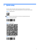
1 Quick setup Use the bar codes in this chapter to perform quick setup procedures for common tasks. Scan the following bar codes in the order listed below to set the scanner back to the HP defaults. Figure 1-1 Set Base Defaults NOTE: Scanning the “Set Base Defaults” bar code does not change the interface type.
OPOS driver The scanner by default is shipped in the human interface device (HID) keyboard emulation mode. In order to use the barcode scanner with OLE for Retail POS (OPOS) drivers the scanner must be put into USB COM (OPOS) mode. For your convenience the bar code to put the scanner into USB COM (OPOS) mode or into HID keyboard emulation are located in this document. Refer to the Programming Reference Guide (PRG) for complete list of barcodes.
Figure 1-8 Set HP Defaults Figure 1-9 Set Global Suffix Figure 1-10 0 Figure 1-11 D Figure 1-12 Exit Global Suffix Mode Figure 1-13 Exit Programming Mode Carriage return 3
Tab Scan the following bar code to set the scanner back to the factory defaults. Figure 1-14 Set Base Defaults NOTE: Scanning the “Set Base Defaults” bar code does not change the interface type.
Figure 1-19 9 Figure 1-20 Exit Global Suffix Mode Figure 1-21 Exit Programming Mode Volume Scan the following bar code to set the scanner back to the factory defaults.
Figure 1-24 Set HP Defaults Figure 1-25 Off Figure 1-26 Low Figure 1-27 Medium Figure 1-28 High 6 Chapter 1 Quick setup
2 Product features HP Value Wireless Barcode Scanner With rich feature sets and extensive options, the HP Value Wireless Barcode Scanner represents the premium level of data collection equipment for general purpose applications. The HP scanner has enhanced optics with improved motion tolerance, allowing codes placed on fast-moving objects to be easily and quickly captured, creating the ideal scanner for tasks requiring high throughput like those found in retail and light industrial environments.
3 Safety and maintenance Ergonomic recommendations WARNING! In order to avoid or minimize the potential risk of ergonomic injury follow the recommendations below. Consult with your local Health & Safety Manager to ensure that you are adhering to your company’s safety programs to prevent employee injury.
Cleaning Exterior surfaces and scan windows exposed to spills, smudges or debris require periodic cleaning to ensure best performance during scanning operations. Contacts on the scanner and the base should also be cleaned as needed to ensure a good connection. Figure 3-1 Cleaning Use a soft, dry cloth to clean the product. If the product is very soiled, clean it with a soft cloth moistened with a diluted non-aggressive cleaning solution or diluted ethyl alcohol.
4 Setting up and using the scanner Follow the steps below to connect and get the scanner up and communicating with its host. 1. Configure the Base Station starting on this page. 2. Charge the Batteries (refer to Charging the batteries on page 15). 3. Link to the Base Station (refer to Linking the scanner on page 19). 4. Select the Interface Type (refer to Selecting the base interface type on page 25). 5.
Figure 4-2 Lock Lever Disengaged 2. Engage the locking mechanism by pushing up the lever as far as it will go. Figure 4-3 Lever in Locked Position NOTE: it is good practice to put the scanner in the locked condition at the end of the working shift, or when not in use for an extended period of time. This will ensure that the scanner is fully seated for complete battery recharge.
Connecting the base station You can connect the base station to a terminal, PC, or other host device. Turn off the host before connection and consult the manual for that equipment (if necessary) before proceeding. Connect the interface cable before applying power to the base station. NOTE: The scanner can also be powered by the terminal. When powered by the terminal, the battery charger is automatically set as slow charge.
4. Connect to an AC adapter, and plug the AC power cord into the (wall) outlet. Figure 4-6 Connecting the Base Station 1 Interface cable 4 AC/DC adapter 2 Base station 5 Wall plug connector 3 DC power cord Host Connection — Verify before connection that the scanner’s cable type is compatible with your host equipment. NOTE: The scanner can be set up to require a PIN code when connecting to the host.
2 USB 3 Wand 5 Keyboard wedge Power Connection — Plug the AC adapter into an approved AC wall socket with the cable facing downwards to prevent undue strain on the socket. System and network layout The figure below shows the typical setup with the host and base station. Figure 4-8 Scanner Layout 1 Host 2 Scanner 3 Base station Using the base Base LEDs LEDs on the base provide information about the base as well as battery charging status, as shown below. Figure 4-9 Base Station LEDs No.
No. Icon LED STATUS 2 Charging Red On = the Battery is charging. 2 Charge completed Green On = the Battery is completely charged. 2 Charging + Charge completed Red and Green Blinking together = the Reader is not correctly placed onto the Base. Charging the batteries The battery can be charged by connecting the reader directly to a host through the Micro USB connector available in the bottom of the handle, as shown below.
WARNING! Do not place the battery pack in fire or heat. Do not connect the positive terminal and negative terminal of the battery pack to each other with any metal object (such as wire). Do not carry or store the battery pack together with metal objects. Do not pierce the battery pack with nails, strike it with a hammer, step on it or otherwise subject it to strong impacts or shocks. Do not solder directly onto the battery pack. Do not expose the battery pack to liquids, or allow the battery to get wet.
The useful life of LI batteries depends on usage and number of charges, etc., after which they should be removed from service, especially in mission critical applications. Do not continue to use a battery showing excessive loss of capacity, it should be properly recycled / disposed of and replaced.
Using the scanner The scanner normally functions by capturing and decoding codes. The aiming system is activated on trigger pull and indicates the center of the field of view which should be positioned over the bar code: Figure 4-13 Aiming System Figure 4-14 Linear bar code Figure 4-15 2D Matrix symbol A beam illuminates the label. The projected pattern of the aiming system will be smaller when the reader is closer to the bar code and larger when it is farther from the code.
Linking the scanner Link RF devices to base For RF devices, before configuring the interface it is necessary to link the handheld with the base. To link the handheld and the base, press the trigger to wake up the handheld and mount it into the base. If the scanner was previously linked to another base, you must first press and hold the button on the base (>5 seconds), then scan the Unlink bar code before re-linking to the new base.
NOTE: The scanner can be set up to require a PIN code when connecting. If you want to set up a PIN, or when adding new equipment to a system that uses a custom security PIN, see the Programming Reference Guide (PRG) for information. Variable PIN code Some Bluetooth drivers on the Host (such as WIDCOMM and BlueSoleil 8) require a Variable PIN Code. When attempting connection, the application presents a window that includes a PIN Code which is to be input using the scanner.
Figure 4-23 HID Alt Mode = ON Power off Scan the bar code below to shut off power to the handheld until the next trigger pull. Figure 4-24 Power Off Country mode NOTE: The following bar codes can be used either while in HID mode (when scanner is connected using Bluetooth) or for configuring the base. HID configuration: Scan any one of the bar codes in the table below to set the country for which your PC is localized.
Figure 4-27 Country Mode = Belgium Figure 4-28 Country Mode = Britain Figure 4-29 Country Mode = Croatia* Figure 4-30 Country Mode = Czech Republic* Figure 4-31 Country Mode = Denmark* Figure 4-32 Country Mode = France Figure 4-33 Country Mode = French Canadian* Figure 4-34 Country Mode = Germany 22 Chapter 4 Setting up and using the scanner
Figure 4-35 Country Mode = Hungary* Figure 4-36 Country Mode = Italy Figure 4-37 Country Mode = Japanese 106-key* Figure 4-38 Country Mode = Lithuanian* Figure 4-39 Country Mode = Norway* Figure 4-40 Country Mode = Poland* Figure 4-41 Country Mode = Portugal* Figure 4-42 Country Mode = Romania* Country mode 23
Figure 4-43 Country Mode = Spain Figure 4-44 Country Mode = Sweden Figure 4-45 Country Mode = Slovakia* Figure 4-46 Country Mode = Switzerland* *Supports only the interfaces listed in the Country Mode feature description (Base configuration only) Caps lock state NOTE: The following bar codes can be used either while in HID mode (when reader is connected using Bluetooth) or for configuring the base. This option specifies the format in which the scanner sends character data.
Figure 4-49 Caps Lock State = Caps Lock ON Figure 4-50 Caps Lock State = AUTO Caps Lock Enable Selecting the base interface type Upon completing the physical connection between the base and its host, proceed directly to “Interface Selection” below for information and programming for the interface type the base is connected to (for example: RS-232, Keyboard Wedge, USB, etc.) and scan the appropriate bar code to select your system’s correct interface type.
Figure 4-52 Select RS-232 Wincor-Nixdorf Figure 4-53 Select RS-232 OPOS/UPOS/JavaPOS Figure 4-54 Select USB-COM-(to simulate RS-232 standard interface) Figure 4-55 Select USB-OEM (can be used for OPOS/UPOS/JavaPOS) Keyboard interface Use the programming bar codes to select options for USB Keyboard and Wedge Interfaces.
Figure 4-59 Select KBD-AT-ALT-NK (Keyboard Wedge for IBM AT PS2 with alternate key encoding but without external keyboard) Figure 4-60 Select KBD-XT (PC/XT w/Standard Key Encoding) Figure 4-61 Select KBD-IBM-3153 (Keyboard Wedge for IBM Terminal 3153) Figure 4-62 Select KBD-IBM-M (Keyboard Wedge for IBM Terminals 31xx, 32xx, 34xx, 37xx make only keyboard) Figure 4-63 Select KBD-IBM-MB (Keyboard Wedge for IBM Terminals 31xx, 32xx, 34xx, 37xx make break keyboard) Figure 4-64 Select USB Alternate Keyboard
Figure 4-67 Select USB Keyboard (USB Keyboard with standard key encoding) Scancode tables Reference to the PRG for information about control character emulation which applies to keyboard interfaces. Country mode This feature specifies the country/language supported by the keyboard when configured through the base. See Country mode on page 21 for programming bar codes and information. Caps lock state This option specifies the format in which the reader sends character data.
5 Programming the scanner The scanner is factory-configured with a set of standard default features. After scanning the interface bar code from the Interfaces section, select other options and customize the scanner through use of the programming bar codes available in the Programming Reference Guide (PRG). Check the corresponding features section for your interface, and also the Data Editing and Symbologies chapters of the PRG.
Reading parameters Point the scanner at the target and pull the trigger to enable the aiming system and the illuminator (red beam) to decode the barcode label. The aiming system will briefly switch off during the acquisition time and if no code is decoded will switch on again before the next acquisition. The illuminator will remain on until the symbol is decoded. As you read code symbols, adjust the distance at which you are holding the scanner.
6 Operating modes Scan modes The imager can be set to operate in one of several scanning modes. Trigger Single: When the trigger is pulled, scanning is activated until one of the following occurs: ● a programmable duration1 has elapsed ● a label has been read ● the trigger is released This mode is associated with typical handheld reader operation.
Figure 6-4 Scan Mode = Trigger Pulse Multiple Figure 6-5 Scan Mode = Flashing Figure 6-6 Scan Mode = Always On Figure 6-7 Scan Mode = Stand Mode Pick mode Pick Mode is a Decoding and Transmission process where bar codes that are not within the configurable distance from the center of the aiming pattern are not acknowledged or transmitted to the host. It is active only while the scanner is in Trigger Single mode. If the scanner switches to a different Read Mode, Pick Mode is automatically disabled.
Figure 6-10 Pick Mode = Enable Multiple labels in a volume Enables/disables the ability of scanner to decode multiple labels in the same image. Several programming options are available for this feature, see the PRG for more information.
A Technical support Online technical support For the online access to technical support information, self-solve tools, online assistance, community forums or IT experts, broad multivendor knowledge base, monitoring and diagnostic tools, go to http://www.hp.com/support. Preparing to call technical support If you can not solve a problem, you may need to call technical support.
B Technical specifications The following table contains physical and performance characteristics, user environment and regulatory information. Item Description Physical Characteristics Color White or Black Dimensions Height 6.4”/163 mm Length 3.6”/91 mm Width 1.6”/41 mm Weight (without cable) Approximately 7.1 ounces / 200 g (reader) Approximately 8.
Depth of Field (Typical) 1 Symbology SR: 10mil: 0" - 8.7" (0 - 22cm) 20mil: up to 17.7” (up to 45cm) EAN 7.5mil: 0" - 5.9" (0 - 15cm) 113mil: 0.2" - 13.8" (0.5 - 35cm) PDF-417 6.6mil: 0.39" - 5.1" (1.0 - 130cm) 10mil: 0" - 8.3" (0 - 21cm) 15mil: 0.2" - 9.5" (0.5 - 24cm) DataMatrix 10mil: 0.39" - 5.1" (1.0 - 13 cm) 15mil: 0" - 7.1" (0 - 18cm) QR Code 10mil: 0.2" - 5.1" (0.5 - 13cm) 15mil: 0" - 7.1" (0 - 18cm) Minimum Element Width Standard Range: 1D Min. Resolution = 4 mil PDF-417 Min.
Decode Capability 1D Bar Codes RS-232 Std, RS-232 Wincor-Nixdorf, RS-232 OPOS, USB Com Std., USB Keyboard, USB Alternate Keyboard, USB OEM, Keyboard Wedge (AT with or w/o Alternate Key, IBM AT PS2 with or w/o Alternate Key, PC-XT, IBM 3153, IBM Terminals 31xx, 32xx,34xx, 37xx make only and make break keyboard, Digital Terminals VT2x, VT3xx, VT4xx, and Apple). It is acceptable to handle this with ULE. a b See Interface selection on page 25 for a listing of available interface sets by version type.
LED and beeper indications The scanner’s beeper sounds and its LED illuminates to indicate various functions or errors on the scanner. An optional “Green Spot” also performs useful functions. The following tables list these indications. One exception to the behaviors listed in the tables is that the scanner’s functions are programmable, and so may or may not be turned on. For example, certain indications such as the power-up beep can be disabled using programming bar code labels.
INDICATION DESCRIPTION LED BEEPER Label Programming Mode Acceptance of Programming Configuration option(s) have been successfully programmed via labels and the scanner has exited programming mode. N/A Scanner sounds one high frequency beep and 4 low frequency beeps followed by reset beeps. Label Programming Mode Cancel Item Entry Cancel label has been scanned. N/A Scanner sounds two times at low frequency and current volume.
C Hex-numeric keypad Use the bar codes that follow to enter numbers as you would select digits/characters from a keypad.
Figure C-8 7 Figure C-9 8 Figure C-10 9 Figure C-11 A Figure C-12 B Figure C-13 C Figure C-14 D Figure C-15 E 41
Figure C-16 F For HID Variable Pin Code only: If you make a mistake, scan the CANCEL barcode below to abort and not save the entry string. You can then restart. Figure C-17 Cancel an Incomplete HID Variable PIN Code Finish by scanning the Exit HID Variable PIN Code label.