HP ElitePad 1000 G2 Maintenance and Service Guide IMPORTANT! This document is intended for HP authorized service providers only.
© Copyright 2015 HP Development Company, L.P. Bluetooth is a trademark owned by its proprietor and used by HP Inc. under license. DTS, the Symbol, & DTS and the Symbol together are registered trademarks, and DTS Sound is a trademark of DTS, Inc. © DTS, Inc. All Rights Reserved. Intel is a U.S. registered trademark of Intel Corporation. Microsoft and Windows are U.S. registered trademarks of Microsoft Corporation. SD Logo is a trademark of its proprietor.
Safety warning notice WARNING! To reduce the possibility of heat-related injuries or of overheating the device, do not place the device directly on your lap or obstruct the device air vents. Use the device only on a hard, flat surface. Do not allow another hard surface, such as an adjoining optional printer, or a soft surface, such as pillows or rugs or clothing, to block airflow. Also, do not allow the AC adapter to contact the skin or a soft surface, such as pillows or rugs or clothing, during operation.
iv Safety warning notice
Table of contents 1 Product description ....................................................................................................................................... 1 2 External component identification ................................................................................................................. 4 Front ....................................................................................................................................................................... 4 Rear .
Microphones ...................................................................................................................................... 40 Rear-facing webcam ......................................................................................................................... 41 Power button board .......................................................................................................................... 42 Volume button board .....................................................
Using HP Sure Start (select products only) ......................................................................................................... 90 7 HP PC Hardware Diagnostics (UEFI) – Windows 10 ........................................................................................... 91 Downloading HP PC Hardware Diagnostics (UEFI) to a USB device .................................................................... 92 8 Computer Setup and HP PC Hardware Diagnostics (UEFI – Windows 8 ................
Questions and answers ..................................................................................................................................... 112 13 Power cord set requirements .................................................................................................................... 113 Requirements for all countries .........................................................................................................................
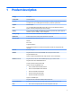
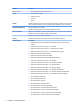
1 Product description Category Description Product Name HP ElitePad 1000 G2 Processor Intel® Atom z3795 1.60-GHz processor (core burst up to 2.39-GHz), 1.60-GHz front-side bus (FSB), 2.0-MB L2 cache, up to 778-MHz graphics burst frequency, soldered to system board Graphics Intel HD Graphics Panel 10.1-in.
Category Description Ports (continued) ● HP ElitePad 900-proprietary docking connector Sensors ● Accelerometer + eCompass ● Ambient light sensor ● Gyroscope ● Haptics Docking HP ElitePad-proprietary dock with 4 standard 2.
Category Description ● Microsoft Windows 8.
2 External component identification Front Item Component Description (1) WWAN antennas (2)* (select models only) Send and receive wireless signals to communicate with WWANs. (2) Front webcam Records video and captures still photographs. For information on using the webcam: 4 ● Windows 10 – Type camera in the taskbar search box, and then select Camera. ● Windows 8 – Access HP Support Assistant. To access HP Support Assistant on the Start screen, select the HP Support Assistant app.
Item Component Description (6) Near Field Communications (NFC) tapping area Allows you to touch an NFC-compatible device to this area to wirelessly connect and communicate with the tablet and transfer data back and forth. (7) Windows button Displays the Start screen. NOTE: The antennas are not visible from the outside of the computer. For optimal transmission, keep the areas immediately around the antennas free from obstructions.
Rear Item Component Description (1) Micro SD Card Reader/Micro SIM slot access hole Allows you to insert the end of a paper clip to open the access door to insert or remove a micro SD card or micro SIM module. (2) Memory card reader/Micro SIM slot Reads optional micro memory cards that store, manage, share, or access information. and supports an optional wireless micro subscriber identity module (SIM) (select models only).
Top Item Component Description (1) Audio-out (headphone) jack/Audio-in (microphone) jack Produces sound when connected to optional powered stereo speakers, headphones, earbuds, a headset, or television audio. Also connects an optional headset microphone. NOTE: When a device is connected to the jack, the computer speakers are disabled. NOTE: Be sure that the device cable has a 4-conductor connector that supports both audio-out (headphone) and audio-in (microphone).
Item Component Description Windows 10: Type power in the taskbar search box, and then select Power and sleep settings. – or – Right-click the Start button, and then select Power Options. Windows 8: See your power options. From the Start screen, type power, select Settings, and then select Power Options. Bottom 8 Item Component Description (1) Speakers (2) Produce sound. (2) Product and regulatory information Displays product and regulatory information (select models only).
3 Illustrated parts catalog NOTE: HP continually improves and changes product parts. For complete and current information on supported parts for your computer, go to http://partsurfer.hp.com, select your country or region, and then follow the on-screen instructions. Service tag When ordering parts or requesting information, provide the tablet serial number and model number provided on the service tag.
Tablet major components 10 Item Component Spare part number (1) Display assembly (10.1-in.
Item Component Spare part number Display Cable Kit, includes: 747625-001 (2a) TouchScreen cable (2b) Display LVDS cable (3) NFC antenna (includes double-sided adhesive) 747633-001 Button Kit, includes: 747634-001 (4a) Power button actuator (4b) Volume button actuator (4c) Autorotate switch actuator (4d) Slot cover hardware (slot cover, retention bracket, spring bracket) (4e) Docking connector bracket Webcam/Microphone Kit, includes: (5a) Left microphone (5b) Right microphone (6a)
Item (12) Component Spare part number Equipped with 128-GB eMMC storage, an NFC module, and the Windows 10 or Windows Embedded Industry 8.
Retail Jacket components Item Description Spare part number (1) Top cap (includes 4 captive screws, secured by C-rings) 744025-001 (2) Battery (2-cell, 21-Wh, 2.
14 Item Description Spare part number (6) Bar code scanner module 744037-001 (7) Cable connector board 744034-001 Cable Kit, includes: 744031-001 (8a) Bar code scanner module cable (8b) Cable connector board cable (8c) Credit card reader board/left board cable (8d) Credit card reader board/right board cable Cable Retainer Kit (20 pieces) 745882-001 (9) Left-side credit card reader board 744027-001 (10) Right-side credit card reader board 744028-001 (11) Credit card reader (includ
Security Jacket components Item Description Spare part number (1) Top cap (includes rubber trim) 744047-001 (2) Card reader cover 744039-001 (3) Front cover 744048-001 (4) Rear cover (includes top cap release latch assembly) 744041-001 (5) Fingerprint reader board 744042-001 (6) Card reader board 744043-001 (7) System board 744044-001 Cables/Connectors Kit, includes: 744045-001 (8a) Fingerprint reader board cable (8b) Card reader board cable (8c) Docking connector cable Secu
Item Description Spare part number Security Jacket equipped with a card reader and a fingerprint reader (not illustrated) 742446-001 Security Jacket equipped with a card reader (not illustrated) 742444-001 Security Jacket Cover (not illustrated) 756037-001 Rubber Kit for use only on the Security Jacket (not illustrated) 744040-001 Screw Kit for use only on the Security Jacket (not illustrated) 744046-001 Healthcare Jacket components (not illustrated) Component Spare part number Healthcare Jac
Rugged Jacket components (not illustrated) Component Spare part number Rugged Jacket: Rugged Jacket with barcode reader 792815-001 Rugged Jacket with barcode reader 827582-001 Rugged Jacket without barcode reader 792813-001 Rugged Jacket without barcode reader 827581-001 70-pin connector 792810-001 Access Covers Kit 792819-001 Back plate: Back plate with SD card reader and USB board 792804-001 Back plate without SD card reader and USB board 793112-001 Back Cover Kit (includes back cover, r
Adapter cables 18 Item Description Spare part number (1) HDMI/VGA adapter cable 695551-001 (2) Ethernet adapter cable 695555-001 (3) Serial adapter cable 695556-001 (4) HP Smart AC adapter cable 695553-001 (5) USB adapter cable 695552-001 (6) Card Reader adapter 695554-001 Chapter 3 Illustrated parts catalog
Docking station and accessories Item Description Spare part number (1) Docking station 708621-001 (2) 40-W HP Smart AC adapter (RC, V, 3-wire) 693717-001 45-W HP Smart AC adapter (non-PFC, 3-wire, 7.4-mm, non-slim) 744893-001 (3) Power cord (3-pin, black, 1.
Item Description Spare part number For use in Switzerland 490371-111 For use in Taiwan 490371-AB1 For use in Thailand 490371-281 For use in the United Kingdom and Singapore 490371-031 Miscellaneous parts Component Spare part number Carrying case: HP ElitePad dockable case 742720-001 HP ElitePad retail case 795131-001 HP ElitePad retail case hand strap 795132-001 HP ElitePad retail case PED mount with tape 795134-001 HP ElitePad rugged case 752759-001 HP ElitePad rugged carrying case
Component Spare part number For use in Germany 724301-041 For use in Greece 724301-151 For use in Hungary 724301-211 For use in Iceland 724301-DD1 For use in India 724301-D61 For use in Israel 724301-BB1 For use in Italy 724301-061 For use in Japan 724301-291 For use in Latin America 724301-161 For use in the Netherlands 724301-B31 For use in Norway 724301-091 For use in Northwest Africa 724301-FP1 For use in Portugal 724301-131 For use in Romania 724301-271 For use in Russia
Power components Item Component (1) 10-W AC adapter for use only on the HP ElitePad 1000 G2: (2) (3) 22 Spare part number Wall-mount, RC/V, 3-wire 686120-001 Wall-mount, non-PFC, 2-wire 746156-001 Duck head power adapter: For use in Argentina 755184-D01 For use in Australia 755184-011 For use in Brazil 755184-201 For use in Denmark 755184-081 For use in Europe 755184-021 For use in India 755184-D61 For use in Israel 755184-BB1 For use in Italy 755184-061 For use in the People's
Item Component Spare part number For use in Denmark 490371-081 For use in Europe 490371-021 For use in India 490371-D61 For use in Israel 490371-BB1 For use in Italy 490371-061 For use in Japan 490371-291 For use in North America 490371-001 For use in the People's Republic of China 490371-371 For use in South Africa 490371-AR1 For use in South Korea 490371-AD1 For use in Switzerland 490371-BG1 For use in Taiwan 490371-AB1 For use in the United Kingdom and Singapore 490371-031 HP
4 Removal and replacement preliminary requirements Tools required You will need the following tools to complete the removal and replacement procedures: ● Magnetic screw driver ● Phillips P0 screw driver ● Plastic case utility tool Service considerations The following sections include some of the considerations that you must keep in mind during disassembly and assembly procedures.
Grounding guidelines Electrostatic discharge damage Electronic components are sensitive to electrostatic discharge (ESD). Circuitry design and structure determine the degree of sensitivity. Networks built into many integrated circuits provide some protection, but in many cases, ESD contains enough power to alter device parameters or melt silicon junctions. A discharge of static electricity from a finger or other conductor can destroy static-sensitive devices or microcircuitry.
Packaging and transporting guidelines Follow these grounding guidelines when packaging and transporting equipment: ● To avoid hand contact, transport products in static-safe tubes, bags, or boxes. ● Protect ESD-sensitive parts and assemblies with conductive or approved containers or packaging. ● Keep ESD-sensitive parts in their containers until the parts arrive at static-free workstations. ● Place items on a grounded surface before removing items from their containers.
Equipment guidelines Grounding equipment must include either a wrist strap or a foot strap at a grounded workstation. ● When seated, wear a wrist strap connected to a grounded system. Wrist straps are flexible straps with a minimum of one megohm ±10% resistance in the ground cords. To provide proper ground, wear a strap snugly against the skin at all times. On grounded mats with banana-plug connectors, use alligator clips to connect a wrist strap.
5 Removal and replacement procedures CAUTION: Components described in this chapter should only be accessed by an authorized service provider. Accessing these parts can damage the computer or void the warranty. NOTE: HP continually improves and changes product parts. For complete and current information on supported parts for your computer, go to http://partsurfer.hp.com, select your country or region, and then follow the on-screen instructions.
2. Place the HP ElitePad Service Tool on a flat, sturdy surface. The HP ElitePad Service Tool is available using spare part number 714222-001. 3. Move the HP ElitePad Service Tool retention bar (1) to the left until the notch (2) in the retention bar allows the retention gate to open. 4. Open the retention gate (3).
5. Place the tablet on the service tool and slide it (1) forward until the tablet docking connector engages with the service tool docking connector (2). 6. Close the retention gate (1) and release the retention bar (2) to secure the tablet in the service tool. 7. Place the suction cup (1) on the lower right corner of the tablet display glass, making sure to place the suction cup inside the edges of the border (2) of the display glass. The suction cup is available using spare part number 714223-001. 8.
9. Lock the two suction cup handles together (4). CAUTION: Do not lift the right edge of the display assembly more than ¼-inch from the tablet when releasing the display assembly. Failure to follow this caution can result in damage to the tablet components. 10. Firmly lift up on the suction cup to release the right side of the display assembly approximately ¼-inch from the tablet. 11. Move the retention bar (1) until the notch in the retention bar allows the retention gate to open.
12. Open the retention gate (2). 13. Slide the tablet out of the service tool (3). 14. Disconnect the suction cup handles (1). 15. Lower the suction cup handle (2). 16. Remove the suction cup (3). 17. Slide the display assembly (1) to the left until the display assembly cables and connectors are accessible. 18. Release the zero insertion force (ZIF) connector (2) to which the TouchScreen cable is attached, and then disconnect the TouchScreen cable (3) from the system board.
19. Release the ZIF connector (4) to which the LVDS cable is attached, and then disconnect the LVDS cable (5) from the system board. 20. Remove the display assembly and cables. 21. If it is necessary to replace the display assembly cables: a. Turn the display assembly upside down, with the bottom toward you. b. Detach the TouchScreen cable (1) from the surface of the display assembly. (The TouchScreen cable is attached to the display assembly with double-sided adhesive.) c.
e. Release the ZIF connector (5) to which the display LVDS cable is attached, and then disconnect the display LVDS cable (6) from the display assembly. The TouchScreen and display LVDS cables are included in the Display Cable Kit, spare part number 718758-001. To install the display assembly: 34 1. Reconnect the display LVDS and TouchScreen cables to the respective ZIF connectors on the display assembly. 2.
NFC antenna Description Spare part number NFC antenna 747633-001 Before removing the NFC antenna, follow these steps: 1. Turn off the tablet. If you are unsure whether the tablet is off or in Hibernation, turn the tablet on, and then shut it down through the operating system. 2. Disconnect the power from the tablet by unplugging the power cord from the tablet. 3. Disconnect all external devices from the tablet. 4. Remove the display assembly (see Display assembly on page 28).
WWAN module Description Spare part number HP lt4226 LTE/HSPA+ 4G Module 736675-005 HP lt4225 LTE/EV-DO Gobi 4G Module 820019-005 HP lt4112 LTE/HSPA+ 4G Module 740011-005 HP lt4111 LTE/EV-DO/HSPA+ 4G Mobile Broadband Module 753080-005 HP hs3110 HSPA+ Intel Mobile Broadband Module 822829-005 Before removing the WWAN module, follow these steps: 1. Turn off the tablet.
4. Remove the WWAN module (4) by sliding it away from the socket on the system board. NOTE: If the WWAN antenna cables are not connected to the terminals on the WWAN module, protective sleeves should be installed on the antenna connectors, as shown in the following illustration. Reverse this procedure to install the WWAN module.
WLAN module Description Spare part number Broadcom BCM43241 802.11abgn 2x2 Wi-Fi + BT 4.0 Combo Adapter 723677-005 Before removing the WLAN module, follow these steps: 1. Turn off the tablet. If you are unsure whether the tablet is off or in Hibernation, turn the tablet on, and then shut it down through the operating system. 2. Disconnect the power from the tablet by unplugging the power cord from the tablet. 3. Disconnect all external devices from the tablet. 4.
5. Remove the WLAN module (5). NOTE: If the WLAN antenna cables are not connected to the terminals on the WLAN module, protective sleeves should be installed on the antenna connectors, as shown in the following illustration. Reverse this procedure to install the WLAN module.
Microphones NOTE: The microphones are included in the Webcam/Microphone Kit, spare part number 762828-001. Before removing the microphones, follow these steps: 1. Turn off the tablet. If you are unsure whether the tablet is off or in Hibernation, turn the tablet on, and then shut it down through the operating system. 2. Disconnect the power from the tablet by unplugging the power cord from the tablet. 3. Disconnect all external devices from the tablet. 4.
Rear-facing webcam NOTE: The rear-facing webcam is included in the Webcam/Microphone Kit, spare part number 762828-001. Before removing the rear-facing webcam, follow these steps: 1. Turn off the tablet. If you are unsure whether the tablet is off or in Hibernation, turn the tablet on, and then shut it down through the operating system. 2. Disconnect the power from the tablet by unplugging the power cord from the tablet. 3. Disconnect all external devices from the tablet. 4.
Power button board Description Spare part number For use only on computer models equipped with the Windows 10 or Windows 8 Professional operating system 753976-601 For use only on computer models equipped with the Windows 10 or Windows 8 Standard operating system 753976-501 For use only on tablet models equipped with the Windows 10 or Windows Embedded Industry 8.
5. Detach the power button board cable (5) from the surface of the battery. (The power button board cable is attached to the battery with double-sided adhesive.) 6. Remove the Phillips PM1.3×2.0 broad head screw (1) and the Phillips PM1.3×2.0 screw (2) that secure the power button board to the bottom cover. 7. Remove the power button board (3) and cable.
NOTE: In the process of removing the power button board, the power button actuator may be accidentally dislodged from the bottom cover. To replace the power button actuator, refer to the following illustration. The power button actuator is included in the Button Kit, spare part number 747634-001. Reverse this procedure to install the power button board.
4. Remove the volume button board (4) and cable. NOTE: In the process of removing the volume button board, the volume button actuator may be accidentally dislodged from the bottom cover. To replace the volume button actuator, refer to the following illustration. The volume button actuator is included in the Button Kit, spare part number 747634-001. Reverse this procedure to install the volume button board.
Audio jack board Description Spare part number Audio jack board (includes audio jack and cable) 747627-001 Before removing the audio jack board, follow these steps: 1. Turn off the tablet. If you are unsure whether the tablet is off or in Hibernation, turn the tablet on, and then shut it down through the operating system. 2. Disconnect the power from the tablet by unplugging the power cord from the tablet. 3. Disconnect all external devices from the tablet. 4.
Vibrator module Description Spare part number Vibrator module (includes cable, double-sided adhesive, plastic cover) 747630-001 Before removing the vibrator module, follow these steps: 1. Turn off the tablet. If you are unsure whether the tablet is off or in Hibernation, turn the tablet on, and then shut it down through the operating system. 2. Disconnect the power from the tablet by unplugging the power cord from the tablet. 3. Disconnect all external devices from the tablet. 4.
Battery Description Spare part number 2-cell, 30-Wh, 4.0-Ah, Li-ion battery (includes battery cable and WWAN/GPS main transceiver and antenna cable) 728558-005 Before removing the battery, follow these steps: 1. Turn off the tablet. If you are unsure whether the tablet is off or in Hibernation, turn the tablet on, and then shut it down through the operating system. 2. Disconnect the power from the tablet by unplugging the power cord from the tablet. 3.
5. Remove the battery (6). Reverse this procedure to install the battery.
System board NOTE: The system board spare part kit is equipped with an Intel Atom z3795 quad core 1.60-GHz processor (burst up to 2.39-GHz; 2.0-MB L2 cache), 4096-MB of system memory, and includes the power button actuator, processor, and replacement thermal material.
3. Release the ZIF connector (3) to which the WLAN ribbon cable is attached, and then disconnect the WLAN ribbon cable from the WLAN module.
52 4. Remove the five Phillips PM1.3×2.0 screws that secure the battery to the bottom cover. 5. Lift the top edge of the system board (1) and swing it up and forward until it rests upside down above the tablet. 6. Remove the two Phillips PM1.3×1.5 broad head screws (2) that secure the docking connector cable to the system board.
7. Disconnect the docking connector cable (3) from the system board. 8. Remove the system board. NOTE: In the process of removing the system board, the autorotate switch actuator may be accidentally dislodged from the bottom cover. To replace the autorotate switch actuator, refer to the following illustration. When installing the autorotate switch actuator, make sure the two tabs (1) on the autorotate switch actuator engage the autorotate switch (2) on the system board.
Reverse this procedure to install the system board. Forward-facing webcam NOTE: The forward-facing webcam is included in the Webcam/Microphone Kit, spare part number 762828-001. Before removing the forward-facing webcam, follow these steps: 1. Turn off the tablet. If you are unsure whether the tablet is off or in Hibernation, turn the tablet on, and then shut it down through the operating system. 2. Disconnect the power from the tablet by unplugging the power cord from the tablet. 3.
2. Release the ZIF connector (1) to which the forward-facing webcam cable is attached, and then disconnect the forward-facing webcam cable (2) from the system board. 3. Remove the forward-facing webcam and cable. Reverse this procedure to install the forward-facing webcam. Slot cover NOTE: The slot cover is included in the Button Kit, spare part number 747634-001. Before removing the slot cover, follow these steps: 1. Turn off the tablet.
3. Remove the slot cover (4) by pressing it through the bottom cover. 4. Remove the slot cover. Reverse this procedure to install the slot cover. Docking connector cable Description Spare part number Docking connector cable (includes double-sided adhesive) 747631-001 Before removing the docking connector cable, follow these steps: 1. Turn off the tablet. If you are unsure whether the tablet is off or in Hibernation, turn the tablet on, and then shut it down through the operating system. 2.
1. Disconnect the vibrator module cable (1) from the docking connector cable. 2. Disconnect the speaker cable (2) from the docking connector cable. 3. Remove the two Phillips PM1.3×2.0 screws (3) that secure the docking connector cable bracket to the bottom cover. 4. Remove the docking connector bracket (4). The docking connector bracket is included in the Button Kit, spare part number 747634-001. 5. Detach the docking connector cable (1) from the surface of the bottom cover.
7. Remove the docking connector cable (3). Reverse this procedure to install the docking connector cable. WLAN antenna NOTE: The WLAN antenna are included in the Antenna Kits and include the WLAN antenna main and auxiliary cables and transceivers.
a. NFC antenna (see NFC antenna on page 35) b. WWAN module (see WWAN module on page 36) c. Power button board (see Power button board on page 42) d. Battery (see Battery on page 48) e. System board (see System board on page 50) Remove the WLAN antenna: 1. Release the WLAN antenna cables from the routing channel (1) built into the bottom cover. 2. Detach the WLAN antenna transceivers (2) from the bottom cover. 3.
WWAN/GPS auxiliary antenna NOTE: The WWAN/GPS auxiliary antenna are included in the Antenna Kits and include the WWAN/GPS auxiliary antenna cable and transceiver. Description Spare part number Antenna Kit for use only in European countries and regions 767884-001 Antenna Kit for use only in Japan 767885-001 Antenna Kit for use only in the United States 767883-001 Before removing the WWAN/GPS auxiliary antenna, follow these steps: 1. Turn off the tablet.
2. Remove the WWAN/GPS auxiliary antenna cable and transceiver (2). Reverse this procedure to install the WWAN/GPS auxiliary antenna.
Speakers Description Spare part number Speakers (include left and right speakers and cables) 747629-001 Before removing the speakers, follow these steps: 1. Turn off the tablet. If you are unsure whether the tablet is off or in Hibernation, turn the tablet on, and then shut it down through the operating system. 2. Disconnect the power from the tablet by unplugging the power cord from the tablet. 3. Disconnect all external devices from the tablet. 4.
3. Remove the speakers (3). Reverse this procedure to install the speakers. Retail Jacket component replacement procedures There are as many as 31 screws that must be removed, replaced, and/or loosened when servicing the Retail Jacket. Make special note of each screw size and location during removal and replacement. Top cap Description Spare part number Top cap (includes 4 captive screws, secured by C-rings) 744025-001 Before disassembling the Retail Jacket, follow these steps: 1.
3. Remove the top cap (2) from the Retail Jacket. CAUTION: Before positioning the Retail Jacket with the tablet display panel facing down, make sure the work surface is clear of tools, screws, and any other foreign objects. Failure to follow this caution can result in damage to the display panel. 4. Turn the Retail Jacket right side up with the bottom toward you. 5. If installed, slide the tablet out of the Retail Jacket. Reverse this procedure to install the top cap.
1. Turn off the tablet. If you are unsure whether the tablet is off or in Hibernation, turn the tablet on, and then shut it down through the operating system. 2. Disconnect the power from the tablet by unplugging the power cord from the tablet or the Retail Jacket. 3. Disconnect all external devices from the Retail Jacket. 4. If installed, remove the tablet from the Retail Jacket (see Top cap on page 63). Remove the battery: 1.
● Battery connector board (see Battery connector board on page 71) ● System board (see System board on page 72) Remove the front cover: 66 1. Position the Retail Jacket with the top toward you. 2. Remove the adhesive-backed liner that covers the front cover. 3. Release the ZIF connector (1) to which the left-side credit card reader board cable is attached, and then disconnect the left-side credit card reader board cable (2) from the left-side credit card reader board.
4. Close the ZIF connector (3). CAUTION: Failure to close the ZIF connector as instructed in step 4 can lead to damage to Retail Jacket components. 5. Position the Retail Jacket with the bottom toward you.
68 6. Remove the two Phillips PM1.3×3.0 screws that secure the front cover to the Retail Jacket. 7. Position the Retail Jacket with the top toward you. 8. Remove the four Phillips PM1.9×3.0 screws that secure the front cover to the Retail Jacket.
9. Remove the front cover by sliding it away from the Retail Jacket. Reverse this procedure to install the front cover. Bar code scanner module and Cable connector board NOTE: The bar code scanner module and cable connector board spare part kits do not include the respective cables. The cables are included in the Cable Kit, spare part number 744031-001.
6. Remove the bar code scanner module (5) and the cable connector board and cable. 7. Turn the bar code scanner module and the cable connector board over so the ZIF connector on the back of the cable connector board is accessible. 8. Release the ZIF connector (1) to which the bar code scanner module cable is attached, and then disconnect the bar code scanner module cable (2) from the cable connector board. Reverse this procedure to install the bar code scanner module and cable connector board.
Battery connector board Description Spare part number Battery connector board (includes cable) 744033-001 Before removing the battery connector board, follow these steps: 1. Turn off the tablet. If you are unsure whether the tablet is off or in Hibernation, turn the tablet on, and then shut it down through the operating system. 2. Disconnect the power from the tablet by unplugging the power cord from the tablet or the Retail Jacket. 3. Disconnect all external devices from the Retail Jacket. 4.
Reverse this procedure to install the battery connector board. System board Description Spare part number System board (includes docking connector and USB port) 744032-001 Before removing the system board, follow these steps: 1. Turn off the tablet. If you are unsure whether the tablet is off or in Hibernation, turn the tablet on, and then shut it down through the operating system. 2. Disconnect the power from the tablet by unplugging the power cord from the tablet or the Retail Jacket. 3.
7. Slide the docking connector (6) out of the opening in the front cover, and then remove the system board. Reverse this procedure to install the system board.
Credit card reader board NOTE: The credit card reader board spare part kits do not include the respective cables. The cables are included in the Cable Kit, spare part number 744031-001. Description Spare part number Left-side credit card reader board 744027-001 Right-side credit card reader board 744028-001 Before removing the credit card reader boards, follow these steps: 1. Turn off the tablet.
3. Release the ZIF connector (3) to which the right-side credit card reader board cable is attached, and then disconnect the right-side credit card reader board cable (4) from the left-side credit card reader board. 4. Remove the left-side credit card reader board. 5. Detach the right-side credit card reader board cable (1) from the rear cover. (The right-side credit card reader board cable is attached to the rear cover with double-sided adhesive.) 6. Remove the Phillips PM1.9×3.
7. Remove the right-side credit card reader board (3) and cable. Reverse this procedure to install the credit card reader boards. Credit card reader Description Spare part number Credit card reader 744026-001 Before removing the credit card reader, follow these steps: 1. Turn off the tablet. If you are unsure whether the tablet is off or in Hibernation, turn the tablet on, and then shut it down through the operating system. 2.
5. Remove the credit card reader (5). Reverse this procedure to install the credit card reader. Security Jacket component replacement procedures There are as many as 13 screws that must be removed, replaced, and/or loosened when servicing the Security Jacket. Make special note of each screw size and location during removal and replacement.
78 1. Place the Security Jacket face down on the work surface with the top cap toward you. 2. Release the card reader cover (1) by sliding it toward the top of the Security Jacket. 3. Remove the card reader cover (2) by lifting it away from the Security Jacket. 4. Remove the Phillips PM1.9×3.0 screw (1) that secures the top cap to the Security Jacket. 5. Slide the top cap release latch (2) to release the top cap from the Security Jacket.
6. Remove the top cap (3) from the Security Jacket. CAUTION: Before positioning the Security Jacket with the tablet display panel facing down, make sure the work surface is clear of tools, screws, and any other foreign objects. Failure to follow this caution can result in damage to the display panel. 7. Turn the Security Jacket right side up with the bottom toward you. 8. If installed, slide the tablet out of the Security Jacket. Reverse this procedure to install the top cap.
Front cover Description Spare part number Front cover 744048-001 Before removing the front cover, follow these steps: 1. Turn off the tablet. If you are unsure whether the tablet is off or in Hibernation, turn the tablet on, and then shut it down through the operating system. 2. Disconnect the power from the tablet by unplugging the power cord from the tablet or the Security Jacket. 3. Disconnect all external devices from the Security Jacket. 4.
5. Release the front cover (2) by sliding it partially away from the Security Jacket. 6. Lift the bottom edge of the front cover (1) and swing it up and back until it rests upside down on the Security Jacket. 7. Disconnect the fingerprint reader board cable (2) from the low insertion force (LIF) connector on the system board. 8. Disconnect the card reader board cable (3) from the LIF connector on the system board. 9. Remove the front cover. Reverse this procedure to install the front cover.
System board Description Spare part number System board (includes docking connector, HDMI port, and USB port) 744044-001 Before removing the system board, follow these steps: 1. Turn off the tablet. If you are unsure whether the tablet is off or in Hibernation, turn the tablet on, and then shut it down through the operating system. 2. Disconnect the power from the tablet by unplugging the power cord from the tablet or the Security Jacket. 3. Disconnect all external devices from the Security Jacket.
Docking connector cable NOTE: The docking connector cable is included in the Cables/Connectors Kit, spare part number 744045-001. Before removing the docking connector cable, follow these steps: 1. Turn off the tablet. If you are unsure whether the tablet is off or in Hibernation, turn the tablet on, and then shut it down through the operating system. 2. Disconnect the power from the tablet by unplugging the power cord from the tablet or the Security Jacket. 3.
Reverse this procedure to install the docking connector cable. Card reader board Description Spare part number Card reader board 744043-001 Before removing the card reader board, follow these steps: 1. Turn off the tablet. If you are unsure whether the tablet is off or in Hibernation, turn the tablet on, and then shut it down through the operating system. 2. Disconnect the power from the tablet by unplugging the power cord from the tablet or the Security Jacket. 3.
Fingerprint reader board Description Spare part number Fingerprint reader board 744042-001 Before removing the fingerprint reader board, follow these steps: 1. Turn off the tablet. If you are unsure whether the tablet is off or in Hibernation, turn the tablet on, and then shut it down through the operating system. 2. Disconnect the power from the tablet by unplugging the power cord from the tablet or the Security Jacket. 3. Disconnect all external devices from the Security Jacket. 4.
6 Computer Setup (BIOS), TPM, and HP Sure Start – Windows 10 Using Computer Setup Computer Setup, or Basic Input/Output System (BIOS), controls communication between all the input and output devices on the system (such as disk drives, display, keyboard, mouse, and printer). Computer Setup includes settings for the types of devices installed, the startup sequence of the computer, and the amount of system and extended memory. NOTE: Use extreme care when making changes in Computer Setup.
Navigating and selecting in Computer Setup ● To select a menu or a menu item, use the tab key and the keyboard arrow keys and then press enter, or use a pointing device to select the item. NOTE: On tablets without keyboards, you can use your finger to make selections. ● To scroll up and down, select the up arrow or the down arrow in the upper-right corner of the screen, or use the up arrow key or the down arrow key on the keyboard.
Updating the BIOS Updated versions of the BIOS may be available on the HP website. Most BIOS updates on the HP website are packaged in compressed files called SoftPaqs. Some download packages contain a file named Readme.txt, which contains information regarding installing and troubleshooting the file. Determining the BIOS To decide whether you need to update Computer Setup (BIOS), first determine the BIOS version on your computer.
NOTE: If you connect your computer to a network, consult the network administrator before installing any software updates, especially system BIOS updates. BIOS installation procedures vary. Follow any instructions that are revealed on the screen after the download is complete. If no instructions are revealed, follow these steps: 1. Type file in the taskbar search box, and then select File Explorer. 2. Select your hard drive designation. The hard drive designation is typically Local Disk (C:). 3.
TPM BIOS settings (select products only) IMPORTANT: Before enabling Trusted Platform Module (TPM) functionality on this system, you must ensure that your intended use of TPM complies with relevant local laws, regulations and policies, and approvals or licenses must be obtained if applicable. For any compliance issues arising from your operation/usage of TPM which violates the above mentioned requirement, you shall bear all the liabilities wholly and solely.
7 HP PC Hardware Diagnostics (UEFI) – Windows 10 HP PC Hardware Diagnostics is a Unified Extensible Firmware Interface (UEFI) that allows you to run diagnostic tests to determine whether the computer hardware is functioning properly. The tool runs outside the operating system so that it can isolate hardware failures from issues that are caused by the operating system or other software components.
Downloading HP PC Hardware Diagnostics (UEFI) to a USB device There are two options to download HP PC Hardware Diagnostics to a USB device: Download the latest UEFI version: 1. Go to http://www.hp.com/go/techcenter/pcdiags. The HP PC Diagnostics home page is displayed. 2. In the HP PC Hardware Diagnostics section, click the Download link, and then select Run. Download any version of UEFI for a specific product: 1. Go to http://www.hp.com/support, and then select your country.
8 Computer Setup and HP PC Hardware Diagnostics (UEFI – Windows 8 Using Computer Setup Computer Setup, or F10 BIOS Setup (Basic Input/Output System), controls communication between all the input and output devices on the system (such as disk drives, display, keyboard, mouse, and printer). Computer Setup includes settings for the types of devices installed, the startup sequence of the tablet, and the amount of system and extended memory. NOTE: Use extreme care when making changes in Computer Setup.
Navigating and selecting in Computer Setup To navigate and select in Computer Setup, follow these steps: 1. Shut down the tablet. 2. To power on the tablet, press the Power button and Volume down button simultaneously. The Startup menu is displayed. 3. Press f10 to enter Computer Setup. ● Tap a menu or a menu item to select it. ● To close open dialog boxes and return to the main Computer Setup screen, tap Escape, and then follow the on-screen instructions. 4.
Updating the BIOS Updated versions of the BIOS may be available on the HP website. Most BIOS updates on the HP website are packaged in compressed files called SoftPaqs. Some download packages contain a file named Readme.txt, which contains information regarding installing and troubleshooting the file.
NOTE: If you connect your tablet to a network, consult the network administrator before installing any software updates, especially system BIOS updates. BIOS installation procedures vary. Follow any instructions that are revealed on the screen after the download is complete. If no instructions are revealed, follow these steps: 1. Swipe from the right edge of the touch screen, tap Search, and then tap the search box. Type file, and then tap File Explorer. 2. Select your hard drive designation.
9 Specifications Tablet specifications Metric U.S. Width 17.80 cm 7.0 in Depth 26.10 cm 10.28 in Height 0.92 cm 0.36 in Weight 0.68 kg 1.50 lbs Dimensions Input power Operating voltage and current 9 V DC @ 1.
10 Backup and recovery – Windows 10 This chapter provides information about the following processes. The information in the chapter is standard procedure for most products. ● Creating recovery media and backups ● Restoring and recovering your system For additional information, refer to the HP support assistant app. ▲ Type support in the taskbar search box, and then select the HP Support Assistant app. ‒ or – Click the question mark icon in the taskbar.
Creating HP Recovery media (select products only) If possible, check for the presence of the Recovery partition and the Windows partition. From the Start menu, select File Explorer, and then select This PC. ● If your computer does not list the Windows partition and the Recovery partition, you can obtain recovery media for your system from support. See the Worldwide Telephone Numbers booklet included with the computer. You can also find contact information on the HP website. Go to http://www.hp.
Using Windows Tools You can create recovery media, system restore points, and backups of personal information using Windows tools. NOTE: If storage is 32 GB or less, Microsoft System Restore is disabled by default. For more information and steps, see the Get started app. ▲ Select the Start button, and then select the Get started app. Restore and recovery There are several options for recovering your system.
Recovering using HP Recovery Manager HP Recovery Manager software allows you to recover the computer to its original factory state by using the HP Recovery media that you either created or that you obtained from HP, or by using the HP Recovery partition (select products only). If you have not already created recovery media, see Creating HP Recovery media (select products only) on page 99.
Using the HP Recovery partition (select products only) The HP Recovery partition allows you to perform a system recovery without the need for recovery discs or a recovery USB flash drive. This type of recovery can be used only if the hard drive is still working. To start HP Recovery Manager from the HP Recovery partition: IMPORTANT: For a tablet with a detachable keyboard, connect the keyboard to the keyboard dock before beginning these steps (select products only). 1.
Changing the computer boot order If your computer does not restart in HP Recovery Manager, you can change the computer boot order, which is the order of devices listed in BIOS where the computer looks for startup information. You can change the selection to an optical drive or a USB flash drive. To change the boot order: IMPORTANT: For a tablet with a detachable keyboard, connect the keyboard to the keyboard dock before beginning these steps. 1. Insert the HP Recovery media. 2.
11 Backup and recovery – Windows 8 To protect your information, use Windows backup and restore utilities to back up individual files and folders, back up your entire hard drive, create system repair media (select models only) by using an optional external flash drive, or an optional external optical drive, or create system restore points. In case of system failure, you can use the backup files to restore the contents of your tablet. 1.
CAUTION: Some Startup Repair options will completely erase and reformat the hard drive. All files you have created and any software installed on the computer are permanently removed. When reformatting is complete, the recovery process restores the operating system, as well as the drivers, software, and utilities from the backup used for recovery. NOTE: An external keyboard, mouse, and external flash drive may be required to perform this procedure. 1. If possible, back up all personal files. 2.
4. To power on the tablet, press the Power button and Volume down button simultaneously. The Startup menu is displayed. 5. Tap F9 Boot Options. 6. Select the external flash drive as the boot device. 7. Restart the tablet.
Using Windows Refresh or Windows Reset When your tablet is not working properly and you need to regain system stability, the Windows Refresh option allows you to start fresh and keep what is important to you. The Windows Reset option allows you to perform detailed reformatting of your tablet, or remove personal information before you give away or recycle your tablet. For more information on these features, see Windows Help and Support.
12 Statement of Volatility The purpose of this document is to provide general information regarding non-volatile memory in industrystandards based HP Business Notebook PC systems and provide general instructions for restoring nonvolatile memory that can contain personal data after the system has been powered off and the hard drive has been removed. HP Business Notebook PC products that use Intel-based or AMD®-based system boards contain volatile DDR memory.
Configuration, then AMT Options. Then select Un-configure AMT on next boot. Select Save, then Yes. Select the File menu, and then select Save Changes and Exit. Reboot the system and confirm that you want to un-configure AMT. 2. j. If the optional Intel Anti-Theft Technology (AT) was activated, contact the provider to deactivate it. k. If the optional Absolute® Software Computrace® management and tracking service was activated on the notebook PC, contact the provider to deactivate it. l.
Non Volatile Memory Type Amount (Size) Does this memory store customer data? Does this memory retain data when power is removed? What is the purpose of this memory? How is data input into this memory? How is this memory write protected? render the NIC nonfunctional. Keyboard ROM 64 KBytes (not customer accessible) No Yes Stores firmware code (keyboard, mouse, & battery management). Programmed at the factory. Code is updated when the system BIOS is updated.
Non Volatile Memory Type Amount (Size) Does this memory store customer data? Does this memory retain data when power is removed? What is the purpose of this memory? How is data input into this memory? How is this memory write protected? setup utility. The third party data store contents can populated by a remote management console or local applications registered by an administrator to have access to the space. can be applied using this utility.
Non Volatile Memory Type Amount (Size) Does this memory store customer data? Does this memory retain data when power is removed? What is the purpose of this memory? How is data input into this memory? How is this memory write protected? write to the flash. Questions and answers 1. 2. How can the BIOS settings be restored (returned to default settings)? a. Turn on or restart the computer and press F10 when prompted near the bottom of the display. b. Select File, then select Restore defaults. c.
13 Power cord set requirements The wide-range input feature of the computer permits it to operate from any line voltage from 100 to 120 volts AC, or from 220 to 240 volts AC. The 3-conductor power cord set included with the computer meets the requirements for use in the country or region where the equipment is purchased. Power cord sets for use in other countries and regions must meet the requirements of the country or region where the computer is used.
Country/region Accredited agency Applicable note number Sweden SEMKO 1 Switzerland SEV 1 Taiwan BSMI 4 The United Kingdom BSI 1 The United States UL 2 1. The flexible cord must be Type HO5VV-F, 3-conductor, 1.0-mm² conductor size. Power cord set fittings (appliance coupler and wall plug) must bear the certification mark of the agency responsible for evaluation in the country or region where it will be used. 2. The flexible cord must be Type SPT-3 or equivalent, No. 18 AWG, 3-conductor.
14 Recycling When a non-rechargeable or rechargeable battery has reached the end of its useful life, do not dispose of the battery in general household waste. Follow the local laws and regulations in your area for battery disposal. HP encourages customers to recycle used electronic hardware, HP original print cartridges, and rechargeable batteries. For more information about recycling programs, see the HP Web site at http://www.hp.com/ recycle.
Index Symbols/Numerics 3G antenna, spare part number 58 70-pin connector, spare part number 16, 17 12, A AC adapter cable, spare part number 18 AC adapter, spare part numbers 19, 22, 23 Access Covers Kit, spare part number 17 adapter cables illustrated 18 spare part numbers 18 adhesive cover spare part number 13 ambient light sensor 4 antenna location 4 removal 58, 60 spare part numbers 12, 58, 60 Antenna Kit, spare part numbers 12, 58, 60 audio jack board removal 46 spare part number 12, 46 audio, produc
E electrostatic discharge 25 equipment guidelines 27 Ethernet adapter cable, spare part number 18 Ethernet, product description 1 F fingerprint reader board removal 85 spare part number 15, 85 forward-facing webcam removal 54 spare part number 54 front components 4 front cover removal 65, 80 spare part numbers 13, 15, 65, 80 Front Cover Kit, spare part number 16, 17 G graphics, product description 1 grounding guidelines 25 guidelines equipment 27 grounding 25 packaging 26 transporting 26 workstation 26 H ha
rear-facing webcam removal 41 spare part number 41 regulatory information 6, 8 removal/replacement procedures 28 Retail Jacket, spare part numbers 14 Rubber Kit, spare part numbers 14, 16 Rugged Jacket, spare part numbers 17 S Screw Kit, spare part numbers 14, 16, 17, 21, 23 SD Card reader cover, spare part number 16 Security Jacket Cover, spare part numbers 16 Security Jacket, spare part numbers 16 security, product description 2 sensors, product description 2 serial adapter cable, spare part number 18 ser