HP EliteBook Folio 1040 G1 Notebook PC Maintenance and Service Guide
© Copyright 2013, 2014 Hewlett-Packard Development Company, L.P. Bluetooth is a trademark owned by its proprietor and used by Hewlett-Packard Company under license. Intel and Core are U.S. registered trademarks of Intel Corporation. Microsoft and Windows are U.S. registered trademarks of the Microsoft group of companies.SD Logo is a trademark of its proprietor. The information contained herein is subject to change without notice.
Safety warning notice WARNING! To reduce the possibility of heat-related injuries or of overheating the device, do not place the device directly on your lap or obstruct the device air vents. Use the device only on a hard, flat surface. Do not allow another hard surface, such as an adjoining optional printer, or a soft surface, such as pillows or rugs or clothing, to block airflow. Also, do not allow the AC adapter to contact the skin or a soft surface, such as pillows or rugs or clothing, during operation.
iv Safety warning notice
Table of contents 1 Product description ....................................................................................................................................... 1 2 External component identification ................................................................................................................. 5 Display ................................................................................................................................................................... 5 Top ....
5 Removal and replacement procedures for Authorized Service Provider parts ................................................... 34 Component replacement procedures ................................................................................................................. 34 Display assembly components (panel, bezel, webcam, microphone) ............................................. 35 Bottom cover ...........................................................................................................
Computer Setup (BIOS), MultiBoot, and HP PC Hardware Diagnostics (UEFI) in Windows 7 .................................. 79 Using Computer Setup ......................................................................................................................................... 79 Starting Computer Setup .................................................................................................................. 79 Navigating and selecting in Computer Setup ........................................
Using Windows Refresh or Windows Reset ...................................................................................... 95 Using HP Software Setup .................................................................................................................. 95 11 Backup and recovery in Windows 7 .............................................................................................................. 96 Creating recovery media and backups .......................................................
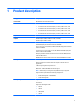
1 Product description Category Description Product Name HP EliteBook Folio 1040 G1 Notebook PC Processors Intel® Core® processors: ● i7-4650U 1.7-GHz (max turbo frequency 3.3-GHz), 4-MB L3 Cache, 15W ● i7-4600U 2.1-GHz (max turbo frequency 3.3-GHz), 4-MB L3 Cache, 15W ● i5-4300U 1.9-GHz (max turbo frequency 2.9-GHz), 3-MB L3 Cache, 15W ● i5-4200U 1.6-GHz (max turbo frequency 2.
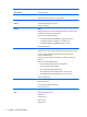
Category Description Audio and video Two stereo speakers HD audio with DTS Studio Sound Integrated 720p webcam (supports no camera option) Integrated dual-array microphone Ethernet Intel I218LM Gigabit Network Connection S3/S4/S5 wake on LAN Wireless WLAN Integrated wireless local area network (WLAN) options by way of wireless module Two WLAN antennas built into display assembly Support for the following WLAN formats: ● Intel Dual Band Wireless-N 7260AN 802.11 a/b/g/n 2x2 WiFi + BT4.
Category Description USB 3.
Category Description Restore media–SR-DVD: ● SuSE Linux Enterprise (SLED) 64-bit, Service Pack 2 Restore media–OS-DVD: ● Windows 8.1 Professional 64-bit ● Windows 8.1 64-bit ● Windows 8.1 Country Specific 64-bit ● Windows 8.1 Emerging Market 64-bit ● Windows 7 Home Premium 64- and 32-bit ● Windows 7 Professional 64- and 32-bit Certified: ● SuSE Linux Enterprise (SLED) 64-bit Service Pack 2 ● Microsoft WHQL Web-only support: Serviceability ● Windows 8.
2 External component identification Display Component Description (1) WLAN antennas (2)* (select models only) Send and receive wireless signals to communicate with wireless local area networks (WLAN). (2) WWAN antennas (2)* (select models only) Send and receive wireless signals to communicate with wireless wide area networks (WWAN). (3) Internal microphones (2) Record sound. (4) Webcam light (select models only) On: The webcam is in use.
Component Description (7) Send and receive wireless signals to communicate and transfer data/ info to and from your Near Field Communication (NFC)-compatible devices. Near Field Communication (NFC) antenna* (select models only) *The antennas are not visible on the outside of the computer. For optimal transmission, keep the areas immediately around the antennas free from obstructions.
Lights Component (1) Description Power light ● On: The computer is on. ● Blinking: The computer is in the Sleep state. ● Off: The computer is off. (2) Caps lock light On: Caps lock is on. (3) ForcePad light ● Amber: The ForcePad is off. ● Off: The ForcePad is on. ● Amber: Microphone sound is off. ● Off: Microphone sound is on. (4) Microphone mute light (5) Num lock light On: Num lock is on.
Buttons and fingerprint reader Component (1) Description Power button ● When the computer is off, press the button to turn on the computer. ● When the computer is on, press the button briefly to initiate Sleep. ● When the computer is in the Sleep state, press the button briefly to exit Sleep. ● When the computer is in Hibernation, press the button briefly to exit Hibernation. CAUTION: Pressing and holding down the power button will result in the loss of unsaved information.
Component Description (2) Speaker grill Produce sound. (3) Wireless button Turns the wireless feature on or off but does not establish a wireless connection. (4) Volume mute button Mutes and restores speaker sound. (5) Fingerprint reader Allows a fingerprint logon to Windows, instead of a password logon. Keys Windows models Component Description (1) esc key Displays system information when pressed in combination with the fn key.
Component Description Each key on the keypad performs the function indicated by the icon in the upper-right corner of the key. (6) Operating system applications key Windows 8: Displays options for a selected object. Windows 7 and Linux: Displays a shortcut menu for items beneath the cursor. (7) num lk key Turns the embedded numeric keypad on and off when pressed in combination with the fn key. Alternates between the navigational and numeric functions on the integrated numeric keypad.
Component Description Displays a shortcut menu for items beneath the cursor. (6) num lk key Turns the embedded numeric keypad on and off when pressed in combination with the fn key. Alternates between the navigational and numeric functions on the integrated numeric keypad. Left Component (1) Description Security cable slot Attaches an optional security cable to the computer.
Right Component (1) Description SIM slot plug (select models only) Supports a wireless subscriber identity module (SIM). For more information about SIM slot inserts and covers, see SIM slot on page 71. (2) Audio-out (headphone) jack/Audio-in (microphone) jack Produces sound when connected to optional powered stereo speakers, headphones, earbuds, a headset, or television audio. Also connects an optional headset microphone.
Bottom Component Description (1) Docking device receptors (2) Connects an optional docking device. (2) Vents (2) Enable airflow to cool internal components. NOTE: The computer fan starts up automatically to cool internal components and prevent overheating. It is normal for the internal fan to cycle on and off during routine operation.
Service tag and PCID label Service tag When ordering parts or requesting information, provide the computer serial number and model description provided on the service tag. 14 ● Product name (1). This is the product name affixed to the front of the computer. ● Serial number (s/n) (2). This is an alphanumeric identifier that is unique to each product. ● Part number/Product number (p/n) (3). This number provides specific information about the product's hardware components.
PCID label The PCID label provides the information required to properly reset the notebook firmware (BIOS) back to factory shipped specifications when replacing the system board. The label may have a different number of characters depending on the operating system on the computer.
3 Illustrated parts catalog Computer major components 16 Chapter 3 Illustrated parts catalog
Item Component Spare part number (1) Display assembly: Non-touch display assemblies are spared at the subcomponent level only. For more non-touch display assembly spare part information, see Display assembly subcomponents on page 20. (2) Keyboard (backlit; includes keyboard cable and backlight cable): 739563-xx1 NOTE: For a detailed list of available keyboards, see Sequential part number listing on page 24.
Item Component Spare part number ● 760276-501 Intel Core i5-4200U processor (1.60 GHz [2.6-GHz max turbo frequency], 3-MB cache) For use in non-touch models with Windows 8 Professional: ● Intel Core i7-4650U processor (1.70 GHz [3.3-GHz max turbo frequency], 4-MB cache) 739583-601 ● Intel Core i7-4600U processor (2.10 GHz [2.8-GHz max turbo frequency], 4-MB cache) 748354-601 ● Intel Core i5-4300U processor (1.90 GHz [2.
Item (19) Component Spare part number 128-GB, SATA III 746907-001 Base enclosure (includes feet) For use in non-touch models 739560-001 For use in touch models 760273-001 Cable Kit (not illustrated) 739564-001 NFC module antenna NFC module cable Function board cable HP Mobile Connect 714749-001 Computer major components 19
Display assembly subcomponents Item Component (1) Display bezel: For use on models with a webcam 739568-001 For use on models without a webcam 748015-001 (2) Display cable 739573-001 (3) Webcam/microphone module 739570-001 Microphone module 739571-001 (4) 20 Spare part number 35.6-cm (14.
Plastics Kit Item Component Spare part number Plastics Kit 739575-001 (1) SIM card slot cover (for WWAN SKU) (2) SIM card insert (for non-WWAN SKU – customer non-removable) Rubber antenna cover (not illustrated) Mass storage devices Item Description (1) Solid-State Drive (SATA III) Spare part number 256-GB 746906-001 180-GB 746908-001 180-GB, self-encrypting 763997-001 128-GB 746907-001 Plastics Kit 21
Miscellaneous parts Component Spare part number AC adapter: 45-W HP Smart AC adapter (non-PFC) 721092-001 45-W AC adapter (non-PFC), 2-prong 742436-001 65-W HP Smart AC adapter 714657-001 65-W HP Smart AC travel adapter 693716-001 Mouse: HP USB optical travel mouse 434594-001 HP USB Laser 674318-001 HP Comfort Grip Wireless Mouse 691922-001 Power cord (3-pin, black, 1.
Component Spare part number For use in India 755530-D61 For use in Israel 755530-BB1 For use in Italy 755530-061 For use in Japan 755530-291 For use in North America 755530-001 For use in the People's Republic of China 755530-AA1 For use in South Africa 755530-AR1 For use in South Korea 755530-AD1 For use in Switzerland 755530-111 For use in Taiwan 755530-AB1 For use in Thailand 755530-201 For use in the United Kingdom 755530-031 Power cord (2-pin, black, 1.
Sequential part number listing CSR flag designations: A = Mandatory B = Optional C = Service technician recommended N = Non-user replaceable 24 Spare part number CSR flag Description 434594-001 A HP USB optical travel mouse 490371-001 A Power cord for use in North America (3-pin, black, 1.83-m) 490371-011 A Power cord for use in Australia (3-pin, black, 1.83-m) 490371-021 A Power cord for use in Europe (3-pin, black, 1.
Spare part number CSR flag Description 717379-005 N Intel Dual Band Wireless-N 7260AN 802.11 a/b/g/n 2x2 WiFi + BT 4.0 717380-005 N Intel Dual Band Wireless-AC 7260 802.11 ac 2x2 WiFi + BT 4.0 718548-001 A HP Business Backpack 718549-001 A HP Business Slim Top Load Case 721092-001 N 45-W HP Smart AC adapter (non-PFC) 722297-005 N 6-cell, 42-Wh, 1.93-Ah 723895-005 N HP hs3110 HSPA+ Mobile Broadband Module 732252-001 A Docking station 735532-005 N Intel Wireless-N 7260BN 802.
26 Spare part number CSR flag Description 739563-281 N Keyboard with backlight for use in Thailand (includes keyboard cable and backlight cable) 739563-291 N Keyboard with backlight for use in Japan (includes keyboard cable and backlight cable) 739563-A41 N Keyboard with backlight for use in Belgium (includes keyboard cable and backlight cable) 739563-AB1 N Keyboard with backlight for use in Taiwan (includes keyboard cable and backlight cable) 739563-AD1 N Keyboard with backlight for use i
Spare part number CSR flag Description 739579-601 N System board with Intel Core i5-4200U processor (1.60 GHz, 3-MB cache) for use in non-touch models with Windows 8 Professional 739580-001 N System board with Intel Core i5-4300U processor (1.90 GHz [2.9-GHz max turbo frequency], 3-MB cache) for use in non-touch models without Windows 8 739580-501 N System board with Intel Core i5-4300U processor (1.90 GHz [2.
28 Spare part number CSR flag Description 755530-061 A Power cord (1.0 m, 3-pin) for use in Italy 755530-081 A Power cord (1.0 m, 3-pin) for use in Denmark 755530-111 A Power cord (1.0 m, 3-pin) for use in Switzerland 755530-201 A Power cord (1.0 m, 3-pin) for use in Thailand 755530-202 A Power cord (1.0 m, 3-pin) for use in Brazil 755530-291 A Power cord (1.0 m, 3-pin) for use in Japan 755530-AA1 A Power cord (1.
Spare part number CSR flag Description 762289-291 A Power cord (1.
4 Removal and replacement procedures preliminary requirements Tools required You will need the following tools to complete the removal and replacement procedures: ● Flat-bladed screw driver ● Torx T8 screw driver ● Phillips P0 and P1 screw drivers ● Non-marking pry tool Service considerations The following sections include some of the considerations that you must keep in mind during disassembly and assembly procedures.
Drive handling CAUTION: Drives are fragile components that must be handled with care. To prevent damage to the computer, damage to a drive, or loss of information, observe these precautions: Before removing or inserting a hard drive, shut down the computer. If you are unsure whether the computer is off or in Hibernation, turn the computer on, and then shut it down through the operating system. Before handling a drive, be sure that you are discharged of static electricity.
Typical electrostatic voltage levels Relative humidity Event 10% 40% 55% Walking across carpet 35,000 V 15,000 V 7,500 V Walking across vinyl floor 12,000 V 5,000 V 3,000 V Motions of bench worker 6,000 V 800 V 400 V Removing DIPS from plastic tube 2,000 V 700 V 400 V Removing DIPS from vinyl tray 11,500 V 4,000 V 2,000 V Removing DIPS from Styrofoam 14,500 V 5,000 V 3,500 V Removing bubble pack from PCB 26,500 V 20,000 V 7,000 V Packing PCBs in foam-lined box 21,000 V 11,0
● Avoid contact with pins, leads, or circuitry. ● Turn off power and input signals before inserting or removing connectors or test equipment. Equipment guidelines Grounding equipment must include either a wrist strap or a foot strap at a grounded workstation. ● When seated, wear a wrist strap connected to a grounded system. Wrist straps are flexible straps with a minimum of one megohm ±10% resistance in the ground cords. To provide proper ground, wear a strap snugly against the skin at all times.
5 Removal and replacement procedures for Authorized Service Provider parts CAUTION: Components described in this chapter should only be accessed by an authorized service provider. Accessing these parts can damage the computer or void the warranty. Component replacement procedures NOTE: Details about your computer, including model, serial number, product key, and length of warranty, are on the service tag at the bottom of your computer. See Service tag and PCID label on page 14 for details.
Display assembly components (panel, bezel, webcam, microphone) All display assemblies include WLAN antenna transceivers and cables. WWAN models also include 2 WWAN antenna transceivers and cables. Full hinge-up displays are not spared. This section describes removing components that do not require that you entirely remove the display assembly from the computer. You can remove the display bezel, webcam/microphone module, and display panel with the display assembly still attached to the computer.
36 b. From the rear of the computer, press through the slightly open computer to disengage the bottom of the bezel (1). c. Open the computer. d. Use a tool to disengage the bottom of the bezel from the display (2), and then remove the bezel from the display (2).
e. 4. Flex the inside edges of the top edge (3), the left and right sides (4), and the bottom edge (5) of the display bezel until the bezel disengages from the display enclosure. The display bezel is available using spare part number 739568-001 on models with a webcam and 748015-001 on models without a webcam. If it is necessary to replace the webcam/microphone module: a. Detach the webcam/microphone module (1) from the display enclosure.
a. Remove the four Phillips PM2.0×2.0 screws that secure the display panel to the display enclosure. ● 739582-001 — 35.6-cm (14.0-in), LED, AntiGlare display panel, UWVA ● 739581-001 — 35.6-cm (14.0-in), LED, AntiGlare display panel, SVA HD+ b. Rotate the top of the display panel downward (1) onto the keyboard. c. Lift the tape that secure the display cable connector on the panel (2), and then disconnect the cable from the connector (3).
Bottom cover NOTE: The bottom cover is available in the Plastics kit, spare part number 739575-001. Description Spare part number Plastics kit 739575-001 Before removing the bottom cover, follow these steps: 1. Turn off the computer. If you are unsure whether the computer is off or in Hibernation, turn the computer on, and then shut it down through the operating system. 2. Disconnect the power from the computer by unplugging the power cord from the computer. 3.
2. Pry up on the top (near the display hinge) of the bottom cover to disengage it from the computer. Reverse the removal procedures to install the bottom cover. When reinstalling the bottom cover, install the screws in the sequence as illustrated in the following image. IMPORTANT: To prevent rocking, be sure to use the correct sequence when installing the screws.
Display assembly This section describes removing components that require you to completely remove the display panel. For more information about removing display components that do not require that you remove the assembly from the computer, see Display assembly components (panel, bezel, webcam, microphone) on page 35. NOTE: The display assembly is spared at the subcomponent level only. Before removing the display assembly, follow these steps: 1. Turn off the computer.
6. If you need to remove the display bezel, webcam/microphone module, or raw display panel, see the related procedures in Display assembly components (panel, bezel, webcam, microphone) on page 35. 7. If it is necessary to replace the display hinges: Display hinges are available in the Display Hinge Kit, spare part number 739572-001. a. Remove the four broadhead Phillips PM2.5×3.0 screws (1) that secure each display hinge to the display enclosure. b.
RTC battery Description Spare part number RTC battery (includes double-sided tape) 739562-001 Before removing the RTC battery, follow these steps: 1. Turn off the computer. If you are unsure whether the computer is off or in Hibernation, turn the computer on, and then shut it down through the operating system. 2. Disconnect the power from the computer by unplugging the power cord from the computer. 3. Disconnect all external devices from the computer. 4.
Battery Description Spare part number 6-cell, 42-Wh, 1.93-Ah, Li ion battery 722297-005 Before disassembling the computer, follow these steps: 1. Turn off the computer. If you are unsure whether the computer is off or in Hibernation, turn the computer on, and then shut it down through the operating system. 2. Disconnect the power from the computer by unplugging the power cord from the computer. 3. Disconnect all external devices from the computer. 4.
3. Lift the battery out of the computer. NOTE: In the locked position there will be no red color shown in the latch slot.
SSD drive Description Spare part number Solid-state drive 256-GB, SATA III 746906-001 180-GB, SATA III 746908-001 180-GB, SATA III, self-encrypting 763997-001 128-GB, SATA III 746907-001 Before removing the hard drive, follow these steps: 1. Turn off the computer. If you are unsure whether the computer is off or in Hibernation, turn the computer on, and then shut it down through the operating system. 2. Disconnect the power from the computer by unplugging the power cord from the computer. 3.
Memory module NOTE: DDR3 memory is not supported. Only DDR3L memory is supported. NOTE: Memory configuration is selected when the computer is ordered and is not upgradeable. Description Spare part number 4-GB memory module (DDR3L, 12800, 1600-MHz) 747221-005 Update BIOS before changing memory module Before changing a memory module, make sure you update the computer to the latest BIOS.
2. Remove the memory module (2) by pulling the module away from the slot at an angle. NOTE: Memory modules are designed with a notch to prevent incorrect insertion into the memory module slot. Reverse this procedure to install a memory module.
WWAN module NOTE: The WWAN module and the WLAN module are not interchangeable.
3. Remove the WWAN module (3) by pulling the module away from the slot. NOTE: WWAN modules are designed with a notch to prevent incorrect insertion. NOTE: If the WWAN antennas are not connected to the terminals on the WWAN module, the protective sleeves must be installed on the antenna connectors, as shown in the following illustration. Reverse this procedure to install the WWAN module.
WLAN module Description Spare part number Intel Dual Band Wireless-N 7260AN 802.11 a/b/g/n 2x2 WiFi + BT 4.0 717379-005 Intel Dual Band Wireless-AC 7260 802.11 ac 2x2 WiFi + BT 4.0 717380-005 Intel Wireless-N 7260BN 802.11 b/g/n 2x2 WiFi + BT 4.0 735532-005 Intel Dual Band Wireless-N 7260AN BT 4.
3. Remove the WLAN module (3) by pulling the module away from the slot at an angle. NOTE: WLAN modules are designed with a notch to prevent incorrect insertion. NOTE: If the WLAN antennas are not connected to the terminals on the WLAN module, the protective sleeves must be installed on the antenna connectors, as shown in the following illustration. Reverse this procedure to install the WLAN module.
Keyboard Description Spare part number Keyboard 739563-xx1 NOTE: For a detailed list of available keyboards, see Sequential part number listing on page 24. Before removing the keyboard, follow these steps: 1. Turn off the computer. If you are unsure whether the computer is off or in Hibernation, turn the computer on, and then shut it down through the operating system. 2. Disconnect the power from the computer by unplugging the power cord from the computer. 3.
54 3. Position the computer open and on its side. 4. Insert a screw driver or similar thin tool into the keyboard release opening under the memory module, and then press on the back of the keyboard until the keyboard disengages from the computer.
5. Lift the rear edge of the keyboard (1), and then remove the keyboard (2). 6. Remove the keyboard. Reverse this procedure to install the keyboard.
ForcePad (Touchpad) Description Spare part number ForcePad (Touchpad) (includes cable) 739565-001 Before removing the ForcePad, follow these steps: 1. Turn off the computer. If you are unsure whether the computer is off or in Hibernation, turn the computer on, and then shut it down through the operating system. 2. Disconnect the power from the computer by unplugging the power cord from the computer. 3. Disconnect all external devices from the computer. 4.
3. Remove the four Phillips PM2.0×2.5 screws (1) that secure the ForcePad to the computer, and then lift the ForcePad from the computer (2).. Reverse the removal procedures to install the ForcePad.
NFC module Description Spare part number NFC (Near Field Communication) module 739578-001 Before removing the NFC module, follow these steps: 1. Turn off the computer. If you are unsure whether the computer is off or in Hibernation, turn the computer on, and then shut it down through the operating system. 2. Disconnect the power from the computer by unplugging the power cord from the computer. 3. Disconnect all external devices from the computer. 4. Bottom cover (see Bottom cover on page 39) 5.
Smart card reader Description Spare part number Smart card reader (includes cable) 739566-001 Before removing the smart card reader, follow these steps: 1. Turn off the computer. If you are unsure whether the computer is off or in Hibernation, turn the computer on, and then shut it down through the operating system. 2. Disconnect the power from the computer by unplugging the power cord from the computer. 3. Disconnect all external devices from the computer. 4.
3. Rotate the bottom up the reader upward at an angle (1), and then remove it from the computer (3). Reverse the removal procedures to install the smart card board.
Power connector Description Spare part number Power connector 749612-001 Before removing the power connector, follow these steps: 1. Turn off the computer. If you are unsure whether the computer is off or in Hibernation, turn the computer on, and then shut it down through the operating system. 2. Disconnect the power from the computer by unplugging the power cord from the computer. 3. Disconnect all external devices from the computer. 4. Bottom cover (see Bottom cover on page 39) 5.
Heat sink/fan assembly NOTE: The heat sink/fan assembly spare part kit includes replacement thermal material. Description Spare part number Heat sink/thermal module with fans 739561-001 Before removing the heat sink/fan assembly, follow these steps: 1. Turn off the computer. If you are unsure whether the computer is off or in Hibernation, turn the computer on, and then shut it down through the operating system. 2. Disconnect the power from the computer by unplugging the power cord from the computer.
4. Using both hands, lift up both fans at the same time and remove the assembly (3). CAUTION: Take extreme care when removing the heat sink and fan assembly. The heatpipes between the fans are very fragile and can be easily damaged and bent during removal. NOTE: The thermal material must be thoroughly cleaned from the surfaces of the heat sink and the system board components each time the heat sink is removed.
Reverse this procedure to install the heat sink/fan assembly. System board NOTE: The system board spare part kit includes replacement thermal material. Description Spare part number System boards for use in non-touch models without Windows 8: Intel Core i7-4650U processor (1.70 GHz, 4-MB cache) 739583-001 Intel Core i7-4600U processor (1.80 GHz, 3-MB cache) 748354-001 Intel Core i5-4300U processor (1.90 GHz, 3-MB cache) 739580-001 Intel Core i5-4200U processor (1.
1. Turn off the computer. If you are unsure whether the computer is off or in Hibernation, turn the computer on, and then shut it down through the operating system. 2. Disconnect the power from the computer by unplugging the power cord from the computer. 3. Disconnect all external devices from the computer. 4. Remove the bottom cover (see Bottom cover on page 39) 5. Remove the keyboard (see Keyboard on page 53) 6. Remove the heat sink/fan assembly (see Heat sink/fan assembly on page 62) 7.
2. Remove the four Phillips PM2.0×3.0 screws that secure the system board to the computer. 3. To remove the system board, be sure to lift near the middle of the board near the connectors as shown by callout (1) in the following image. CAUTION: To avoid damaging or breaking the system board, when removing the board, lift up near the middle of the board. Do not lift up on the narrow end of the board. 4. 66 Lift the right side of the system board up at an angle (2).
5. Pull the system board away from and out of the computer (3), making sure the connectors on the side of the board are clear of the computer. Use the following image to determine all Mylar locations on the system board. Reverse this procedure to install the system board.
Multi-function board Description Spare part number Function board 739574-001 Before removing the function board, follow these steps: 1. Turn off the computer. If you are unsure whether the computer is off or in Hibernation, turn the computer on, and then shut it down through the operating system. 2. Disconnect the power from the computer by unplugging the power cord from the computer. 3. Disconnect all external devices from the computer. 4.
Fingerprint reader board Description Spare part number Fingerprint reader board (includes cable) 739567-001 Before removing the fingerprint reader board, follow these steps: 1. Turn off the computer. If you are unsure whether the computer is off or in Hibernation, turn the computer on, and then shut it down through the operating system. 2. Disconnect the power from the computer by unplugging the power cord from the computer. 3. Disconnect all external devices from the computer. 4.
Speaker assembly Description Spare part number Speaker assembly (includes cable) 739577-001 Before removing the speaker assembly, follow these steps: 1. Turn off the computer. If you are unsure whether the computer is off or in Hibernation, turn the computer on, and then shut it down through the operating system. 2. Disconnect the power from the computer by unplugging the power cord from the computer. 3. Disconnect all external devices from the computer. 4.
SIM slot Description Spare part number Plastics Kit 739575-005 The Plastics Kit includes both the SIM slot insert for use in models with WWAN and the SIM slot cover for use in models without WWAN. Service technicians must remove the system board to remove the SIM slot cover. SIM slot insert (WWAN models) The SIM slot insert, used on WWAN models, matches the size of the SIM card and is customer removable. To insert and remove the SIM slot insert: 1. Insert with the arrow on insert visible. 2.
2. 72 To remove the SIM slot cover, you must first remove the system board, and then pull the cover out of the SIM slot.
6 Computer Setup (BIOS), MultiBoot, and HP PC Hardware Diagnostics (UEFI) in Windows 8 Using Computer Setup Computer Setup, or Basic Input/Output System (BIOS), controls communication between all the input and output devices on the system (such as disk drives, display, keyboard, mouse, and printer). Computer Setup includes settings for the types of devices installed, the startup sequence of the computer, and the amount of system and extended memory.
– or – Use the tab key and the arrow keys to select Main > Ignore Changes and Exit, and then press enter. ● To save your changes and exit Computer Setup menus: Click the Save icon in the lower-right corner of the screen, and then follow the on-screen instructions. – or – Use the tab key and the arrow keys to select Main > Save Changes and Exit, and then press enter. Your changes go into effect when the computer restarts.
1. Start Computer Setup. 2. Use a pointing device or the arrow keys to select Main > System Information. 3. To exit Computer Setup without saving your changes, click the Exit icon in the lower-right corner of the screen, and then follow the on-screen instructions. – or – Use the tab key and the arrow keys to select Main > Ignore Changes and Exit, and then press enter.
Using MultiBoot About the boot device order As the computer starts, the system attempts to boot from enabled devices. The MultiBoot utility, which is enabled at the factory, controls the order in which the system selects a boot device. Boot devices can include optical drives, diskette drives, a network interface card (NIC), hard drives, and USB devices. Boot devices contain bootable media or files that the computer needs to start and operate properly.
Dynamically choosing a boot device using the f9 prompt To dynamically choose a boot device for the current startup sequence, follow these steps: 1. Open the Select Boot Device menu by turning on or restarting the computer, and then pressing esc while the “Press the ESC key for Startup Menu” message is displayed at the bottom of the screen. 2. Press f9. 3. Use a pointing device or the arrow keys to select a boot device, then press enter.
To start HP PC Hardware Diagnostics UEFI: 1. Turn on or restart the computer, quickly press esc, and then press f2. After pressing f2, the BIOS searches three places for the HP PC Hardware Diagnostics (UEFI) tools in the following order: a. Connected USB drive NOTE: To download the HP PC Hardware Diagnostics (UEFI) tool to a USB drive, see Downloading HP PC Hardware Diagnostics (UEFI) to a USB device on page 78. 2. b. Hard drive c.
7 Computer Setup (BIOS), MultiBoot, and HP PC Hardware Diagnostics (UEFI) in Windows 7 Using Computer Setup Computer Setup, or Basic Input/Output System (BIOS), controls communication between all the input and output devices on the system (such as disk drives, display, keyboard, mouse, and printer). Computer Setup includes settings for the types of devices installed, the startup sequence of the computer, and the amount of system and extended memory.
– or – Use the tab key and the arrow keys to select Main > Ignore Changes and Exit, and then press enter. ● To save your changes and exit Computer Setup menus: Click the Save icon in the lower-right corner of the screen, and then follow the on-screen instructions. – or – Use the tab key and the arrow keys to select Main > Save Changes and Exit, and then press enter. Your changes go into effect when the computer restarts.
1. Start Computer Setup. 2. Use a pointing device or the arrow keys to select Main > System Information. 3. To exit Computer Setup without saving your changes, click the Exit icon in the lower-right corner of the screen, and then follow the on-screen instructions. – or – Use the tab key and the arrow keys to select Main > Ignore Changes and Exit, and then press enter.
Using MultiBoot About the boot device order As the computer starts, the system attempts to boot from enabled devices. The MultiBoot utility, which is enabled at the factory, controls the order in which the system selects a boot device. Boot devices can include optical drives, diskette drives, a network interface card (NIC), hard drives, and USB devices. Boot devices contain bootable media or files that the computer needs to start and operate properly.
Dynamically choosing a boot device using the f9 prompt To dynamically choose a boot device for the current startup sequence, follow these steps: 1. Open the Select Boot Device menu by turning on or restarting the computer, and then pressing esc while the “Press the ESC key for Startup Menu” message is displayed at the bottom of the screen. 2. Press f9. 3. Use a pointing device or the arrow keys to select a boot device, then press enter.
To start HP PC Hardware Diagnostics UEFI: 1. Turn on or restart the computer, quickly press esc, and then press f2. After pressing f2, the BIOS searches three places for the HP PC Hardware Diagnostics (UEFI) tools in the following order: a. Connected USB drive NOTE: To download the HP PC Hardware Diagnostics (UEFI) tool to a USB drive, see Downloading HP PC Hardware Diagnostics (UEFI) to a USB device on page 84. 2. b. Hard drive c.
8 Computer Setup (BIOS) and Advanced System Diagnostics in Linux Computer Setup, or Basic Input/Output System (BIOS), controls communication between all the input and output devices on the system (such as disk drives, display, keyboard, mouse, and printer). Computer Setup includes settings for the types of peripherals installed, the startup sequence of the computer, and the amount of system and extended memory. NOTE: Use extreme care when making changes in Computer Setup.
Use the tab key and the arrow keys to select File > Ignore Changes and Exit, and then press enter. – or – ● To save your changes and exit Computer Setup menus, click the Save icon in the lower-left corner of the screen, and then follow the on-screen instructions. – or – Use the tab key and the arrow keys to select File > Save Changes and Exit, and then press enter. Your changes go into effect when the computer restarts.
Use the tab key and the arrow keys to select File > Ignore Changes and Exit, and then press enter. NOTE: You can also determine the BIOS version by turning on or restarting the computer, pressing the esc key while the “Press the ESC key for Startup Menu” message is displayed at the bottom of the screen, and then pressing the f1 key. Follow the on-screen instructions to exit this screen.
● Battery test—This test analyzes the condition of the battery and calibrates the battery if necessary. If the battery fails the test, contact support to report the issue and purchase a replacement battery. ● System Tune-Up—This group of additional tests checks your computer to make sure that the main components are functioning correctly.
9 Specifications Computer specifications Metric U.S. Width 33.80 cm 13.3 in Depth 23.5 cm 9.19 in Height 1.59 cm 0.63 in 1.49 kg 3.3 lbs Dimensions Weight Equipped with one memory module, WLAN module, and mSATA drive Input power Operating voltage and current 18.5 V dc @ 3.5 A - 65 W – or – 19.0 V dc @ 4.
35.6-cm (14.0-in) HD+ display specifications Metric U.S. Height 17.6 cm 6.93 in Width 31.2 cm 12.28 in Diagonal 35.7 cm 14.06 in Number of colors up to 16.8 million Contrast ratio 200:1 (typical) Brightness 250 nits (typical) Dimensions Pixel resolution 90 Pitch 0.197 × 0.197 mm Format HD+ (1600 x 900) Configuration RGB vertical stripe Backlight LED Character display 80 × 25 Total power consumption 3.
35.6-cm (14.0-in) FHD display specifications Metric U.S. Height 17.6 cm 6.93 in Width 31.2 cm 12.28 in Diagonal 35.7 cm 14.06 in Number of colors up to 16.8 million Contrast ratio 200:1 (typical) Brightness 300 nits (typical) Dimensions Pixel resolution Pitch 0.197 × 0.197 mm Format HD+ (1920 x 1080) Configuration RGB vertical stripe Backlight LED Character display 80 × 25 Total power consumption 3.46 W Viewing angle ±65° horizontal, ±50° vertical (typical) 35.6-cm (14.
M.2 solid-state drive specifications 128-GB* 180-GB* 256-GB* Height 1 mm 1 mm 1 mm Length 50.8 mm 50.8 mm 50.8 mm Width 28.9 mm 28.9 mm 28.
10 Backup and recovery in Windows 8 To protect your information, use Windows backup and restore utilities to back up individual files and folders, back up your entire hard drive, create system repair media (select models only) by using the installed optical drive (select models only) or an optional external optical drive, or create system restore points. In case of system failure, you can use the backup files to restore the contents of your computer.
CAUTION: Some Startup Repair options will completely erase and reformat the hard drive. All files you have created and any software installed on the computer are permanently removed. When reformatting is complete, the recovery process restores the operating system, as well as the drivers, software, and utilities from the backup used for recovery. 1. If possible, back up all personal files. 2. If possible, check for the presence of the Recovery Image partition and the Windows partition.
Using Windows operating system media (purchased separately) To order a Windows operating system DVD, contact support. See the Worldwide Telephone Numbers booklet included with the computer. You can also find contact information from the HP website. Go to http://www.hp.com/support, select your country or region, and follow the on-screen instructions. CAUTION: Using a Windows operating system media completely erases hard drive contents and reformats the hard drive.
11 Backup and recovery in Windows 7 Your computer includes HP and Windows tools to help you safeguard your information and retrieve it if you ever need to. These tools will help you return your computer to a proper working state, all with simple steps. This section provides information about the following processes: ● Creating recovery media and backups ● Restoring and recovering your system Creating recovery media and backups Recovery after a system failure is only as good as your most recent backup.
applications if the hard drive becomes corrupted. HP Recovery Disc Creator can create two kinds of recovery DVDs: ● Windows 7 operating system DVD—Installs the operating system without additional drivers or applications. ● Driver Recovery DVD—Installs specific drivers and applications only, in the same way that the HP Software Setup utility installs drivers and applications. Creating recovery media NOTE: The Windows 7 operating system DVD can be created only once.
To create a backup using Windows Backup and Restore: NOTE: The backup process may take over an hour, depending on file size and the speed of the computer. 1. Select Start > All Programs > Maintenance > Backup and Restore. 2. Follow the on-screen instructions to set up your backup, create a system image (select models only), or create system repair media (select models only).
1. If possible, back up all personal files. 2. If possible, check for the presence of the Windows partition. To check for the Windows partition, select Start > Computer. NOTE: If the Windows partition is not listed, you must recover your operating system and programs using the Windows 7 operating system DVD and the Driver Recovery media. For additional information, see Using Windows 7 operating system media on page 99. 3.
To initiate recovery using a Windows 7 operating system DVD: NOTE: This process takes several minutes. 1. If possible, back up all personal files. 2. Restart the computer, and then insert the Windows 7 operating system DVD into the optical drive before the Windows operating system loads. 3. When prompted, press any keyboard key. 4. Follow the on-screen instructions. 5. Click Next. 6. Select Repair your computer. 7. Follow the on-screen instructions. After the repair is completed: 1.
12 Backup and Recovery in Linux Recovery after a system failure is as good as your most recent backup. As you add new software and data files, you should continue to back up your system on a regular basis to maintain a reasonably current backup. Your computer includes tools provided by HP to help you safeguard your information and retrieve it if ever needed. Creating backups 1. Create restore media immediately after you set up the computer.
5. Under Restore Point, click the time and date of the backup. NOTE: If multiple backups have been performed, click Use the latest version to restore the latest version. 6. Click Restore to start restoring the files, or click Cancel to cancel the operation. Performing a system recovery Recovery allows you to repair or restore the computer to its original factory state. You can create an HP Factory Image Restore DVD, using an installed or an external DVD±RW optical drive.
1. Connect the USB Disk On Key to a USB port on the computer. 2. Select Computer > More applications > Tools > Create Recovery USB. 3. Enter the root password when prompted. 4. Select USB Disk On Key from the list. 5. Click OK. 6. A question dialog will remind you that the data on the USB key will be destroyed. To continue, click OK. Otherwise, click Cancel and back up the contents of the Disk On Key on another computer. 7.
– or – Press and hold f11 as you press the power button. The following options are available: ● Cancel/Reboot—Reboots the system. No recovery or restore activity is performed. ● Recover/Repair System—This option repairs a system that is not working properly and preserves user data. ● Restore Factory System—This option restores the system back to the original factory state. User data is not preserved. Select an option and follow the on-screen instructions.
13 Statement of Volatility The purpose of this document is to provide general information regarding non-volatile memory in industrystandards based HP Business Notebook PC systems and provide general instructions for restoring nonvolatile memory that can contain personal data after the system has been powered off and the hard drive has been removed. HP Business Notebook PC products that use Intel®-based or AMD®-based system boards contain volatile DDR memory.
Then select Un-configure AMT on next boot. Select Save then Yes. Select the File menu, and then select Save Changes and Exit. Reboot the system and confirm that you want to un-configure AMT. 2. j. If the optional Intel® Anti-Theft Technology (AT) was activated, contact the provider to de-activate it. k. If the optional Absolute® Software Computrace® management and tracking service was activated on the notebook PC, contact the provider to deactivate it. l.
Non Volatile Memory Type Amount (Size) Does this memory store customer data? Does this memory retain data when power is removed? What is the purpose of this memory? How is data input into this memory? How is this memory write protected? Controller (NIC) EEPROM 64 Kbytes (not customer accessible) No Yes Store NIC configuration and NIC firmware. Using a utility from the NIC vendor that can be run from DOS. A utility is required to write data to this memory and is available from NIC vendor.
Non Volatile Memory Type Amount (Size) Does this memory store customer data? Does this memory retain data when power is removed? What is the purpose of this memory? How is data input into this memory? How is this memory write protected? 802.11 WLAN EEPROM 4kb to 8kb No Yes Stores configuration and calibration data. Programmed at the factory. Tools for writing data to this memory are not made public.
This relates to clearing the Real Time Clock (RTC) CMOS memory that contains PC configuration data. 6. Does resetting the CMOS configuration memory return the PC back to factory defaults? The process of resetting the CMOS will return certain system settings to factory default but will not reset many of the system data and configuration defaults to their factory settings.
14 Power cord set requirements The wide-range input feature of the computer permits it to operate from any line voltage from 100 to 120 volts AC, or from 220 to 240 volts AC. The 3-conductor power cord set included with the computer meets the requirements for use in the country or region where the equipment is purchased. Power cord sets for use in other countries and regions must meet the requirements of the country or region where the computer is used.
Country/region Accredited agency Applicable note number Sweden SEMKO 1 Switzerland SEV 1 Taiwan BSMI 4 The United Kingdom BSI 1 The United States UL 2 1. The flexible cord must be Type HO5VV-F, 3-conductor, 1.0-mm² conductor size. Power cord set fittings (appliance coupler and wall plug) must bear the certification mark of the agency responsible for evaluation in the country or region where it will be used. 2. The flexible cord must be Type SPT-3 or equivalent, No. 18 AWG, 3-conductor.
15 Recycling Battery When a non-rechargeable or rechargeable battery has reached the end of its useful life, do not dispose of the battery in general household waste. Follow the local laws and regulations in your area for battery disposal. HP encourages customers to recycle used electronic hardware, HP original print cartridges, and rechargeable batteries. For more information about recycling programs, see the HP Web site at http://www.hp.com/ recycle. Display WARNING! The backlight contains mercury.
2. Lift up and out on the left and right inside edges (1) and the top and bottom inside edges (2) of the display bezel until the bezel disengages from the display assembly. 3. Remove the display bezel (3). 4. Disconnect all display panel cables (1) from the display inverter and remove the inverter (2). 5. Remove all screws (1) that secure the display panel assembly to the display enclosure.
6. Remove the display panel assembly (2) from the display enclosure. 7. Position the display panel assembly upside-down. 8. Remove all screws that secure the display panel frame to the display panel. 9. Use a sharp-edged tool to cut the tape (1) that secures the sides of the display panel to the display panel frame. 10. Remove the display panel frame (2) from the display panel. 11. Remove the screws (1) that secure the backlight cover to the display panel.
12. Lift the top edge of the backlight cover (2) and swing it outward. 13. Remove the backlight cover. 14. Position the display panel right-side up. 15. Remove the backlight cables (1) from the clip (2) in the display panel. 16. Position the display panel upside-down. WARNING! The backlight contains mercury. Exercise caution when removing and handling the backlight to avoid damaging this component and causing exposure to the mercury.
17. Remove the backlight frame from the display panel. 18. Remove the backlight from the backlight frame. 19. Disconnect the display panel cable (1) from the LCD panel. 20. Remove the screws (2) that secure the LCD panel to the display rear panel. 21. Release the LCD panel (3) from the display rear panel. 22. Release the tape (4) that secures the LCD panel to the display rear panel.
23. Remove the LCD panel. 24. Recycle the LCD panel and backlight.
Index A AC adapter, spare part numbers 22, 25 AC adapter/battery light 12 audio, product description 2 audio-in (microphone) jack, identifying 12 audio-out (headphone) jack, identifying 12 B backup 101 Backup and Restore 98 backup tools 96 backups creating 97 recovering 98 base enclosure spare part number 19, 25 battery removal 44 spare part numbers 18, 25, 44 BIOS determining version 74, 80, 86 downloading an update 75, 81, 87 updating 74, 80, 86 Blu-ray R/RE DVD±RW SuperMulti DL Drive precautions 31 Blu-r
ForcePad buttons 6 removal 56 spare part number 17, 26, 56 ForcePad light, identifying 7 ForcePad zone identifying 6 function board removal 68 spare part number 17, 26, 68 function keys, identifying 9, 10 G graphics, product description 1 grounding guidelines 31 guidelines equipment 33 grounding 31 packaging 32 transporting 32 workstation 32 H hard drive precautions 31 hard drive cover spare part number 39 hard drive recovery 94, 99 headphone (audio-out) jack 12 heat sink removal 62 spare part numbers 17, 2
display panel 1 Ethernet 2 external media cards 2 graphics 1 keyboard 3 memory module 1 microphone 2 operating system 3 pointing device 3 ports 2 power requirements 3 primary storage 1 processors 1 product name 1 security 3 serviceability 4 video 2 wireless 2 product name 1 R recovery 95, 101 recovery media, creating 96 recovery media, using for restore 99 recovery partition 94, 99 recovery tools 96 recovery tools, Windows 98 recovery, system 98 refresh 95 removal/replacement procedures 34 reset 95 computer