HP Stream Notebook PC (model numbers 11-d000 through 11-d099) Maintenance and Service Guide IMPORTANT! This document is intended for HP authorized service providers only.
© Copyright 2014 Hewlett-Packard Development Company, L.P. Bluetooth is a trademark owned by its proprietor and used by Hewlett-Packard Company under license. Intel and Celeron are trademarks or registered trademarks of Intel Corporation in the United States and other countries. Microsoft and Windows are U.S. registered trademarks of Microsoft Corporation. SD Logo is a trademark of its proprietor. The information contained herein is subject to change without notice.
Safety warning notice WARNING! To reduce the possibility of heat-related injuries or of overheating the device, do not place the device directly on your lap or obstruct the device air vents. Use the device only on a hard, flat surface. Do not allow another hard surface, such as an adjoining optional printer, or a soft surface, such as pillows or rugs or clothing, to block airflow. Also, do not allow the AC adapter to contact the skin or a soft surface, such as pillows or rugs or clothing, during operation.
iv Safety warning notice
Table of contents 1 Product description ....................................................................................................................................... 1 2 External component identification ................................................................................................................. 3 Finding your hardware and software information ................................................................................................ 3 Locating hardware ..................
TouchPad ........................................................................................................................................... 33 Heat sink ............................................................................................................................................ 34 Power button board .......................................................................................................................... 35 Battery .....................................................
1 Product description Category Description Product Name HP Stream Notebook PC (model numbers 11-d000 through 11-d099) Processor Intel® Celeron™ N2840 2.16-GHz (SC turbo up to 2.58-GHz) dual core processor (1333-MHz FSB, 1.0-MB L2 cache, 4.5 W) integrated system-on-chip (SoC) Intel Celeron N2830 2.16-GHz (SC turbo up to 2.41-GHz) dual core processor (1333-MHz FSB, 1.0MB L2 cache, 4.
Category Description Ports (continued) ● RJ-45 (Ethernet) ● USB: one USB 3.0 port, 2 USB 2.0 ports Keyboard/pointing devices 97%-size, textured, island-style, keyboard Touchpad requirements: Multitouch gestures enabled Taps enabled as default Support for Microsoft® Windows® 8 Modern trackpad gestures Power requirements Support for a 3-cell, 37-WHr, 3.25-AHr battery Support for a 65-W or 45-W AC adapter with a 1.0-M power cord Security Trusted platform module (TPM) version 2.
2 External component identification Finding your hardware and software information Locating hardware To find out what hardware is installed on your computer: 1. From the Start screen, type control panel, and then select Control Panel. 2. Select System and Security, select System, and then click Device Manager in the left column. A list displays all the devices installed on your computer.
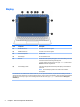
Display Item Component Description (1) WLAN antennas (2)* Send and receive wireless signals. (2) WWAN antennas (2)* Send and receive wireless signals. (3) Internal microphones Record sound. (4) Webcam light On: The webcam is in use. (5) Webcam Records video and captures photographs. Some models allow you to video conference and chat online using streaming video. To use the webcam, from the Start screen, type camera, and then select Camera from the list of applications.
Buttons Item Component Description (1) Power button ● When the computer is off, press the button to turn on the computer. ● When the computer is on, press the button briefly to initiate Sleep. ● When the computer is in Hibernation, press the button briefly to exit Hibernation. CAUTION: Pressing and holding down the power button will result in the loss of unsaved information.
Keys Item Component Description (1) esc key Displays system information when pressed in combination with the fn key. (2) fn key Executes frequently used system functions when pressed in combination with the esc key, or on select models, the spacebar. (3) Windows key Returns you to the Start screen from an open app or the Windows desktop. NOTE: Pressing the Windows key again will return you to the previous screen. (4) Action keys Execute frequently used system functions.
Lights Item Component Description (1) Power light ● On: The computer is on. ● Blinking: The computer is in the Sleep state, a power-saving state. The computer shuts off power to the display and other unneeded components. ● Off: The computer is off or in Hibernation. Hibernation is a power-saving state that uses the least amount of power. (2) Caps lock light On: Caps lock is on, which switches the keys to all capital letters. (3) Mute light ● Amber: Computer sound is off.
TouchPad Item Component Description (1) Touchpad zone Reads your finger gestures to move the pointer or activate items on the screen. NOTE: The TouchPad also supports edgeswipe gestures. 8 (2) Left TouchPad button Functions like the left button on an external mouse. (3) Right TouchPad button Functions like the right button on an external mouse.
Left side Item Component Description (1) Security cable slot Attaches an optional security cable to the computer. NOTE: The security cable is designed to act as a deterrent, but it may not prevent the computer from being mishandled or stolen. (2) Power connector Connects an AC adapter. (3) AC adapter light ● White: The AC adapter is connected and the battery is charged. ● Amber: The AC adapter is connected and the battery is charging. ● Off: The computer is using battery power.
Right side Item Component Description (1) Power light ● On: The computer is on. ● Blinking: The computer is in the Sleep state, a power-saving state. The computer shuts off power to the display and other unneeded components. ● Off: The computer is off or in Hibernation. Hibernation is a power-saving state that uses the least amount of power.
Bottom Item Component Description (1) Speakers (2) Produce sound.
3 Illustrated parts catalog NOTE: HP continually improves and changes product parts. For complete and current information on supported parts for your computer, go to http://partsurfer.hp.com, select your country or region, and then follow the on-screen instructions. Locating the service tag information The product name (1), serial number (2), product number (3), warranty information (4), and model number (5) are located on the bottom of the computer.
Computer major components Item Component (1) Display assembly: The display assembly is spared at the subcomponent level only. For display assembly spare part information, see Display assembly subcomponents on page 17.
Item (3) Component Spare part number In orchid magenta finish 797210-001 Keyboard/top cover (includes cable): In horizon blue finish: For use in Belgium 792906-A41 For use in Bulgaria 792906-261 For use in Canada 792906-DB1 For use in the Czech Republic and Slovakia 792906-FL1 For use in Denmark, Finland, and Norway 792906-DH1 For use in France 792906-051 For use in Germany 792906-041 For use in Greece 792906-151 For use in Hungary 792906-211 For use in Israel 792906-BB1 For use in
Item Component Spare part number For use in Denmark, Finland, and Norway 793836-DH1 For use in France 793836-051 For use in Germany 793836-041 For use in Greece 793836-151 For use in Hungary 793836-211 For use in Israel 793836-BB1 For use in Italy 793836-061 For use in Japan 793836-291 For use in the Netherlands 793836-B31 For use in Portugal 793836-131 For use in Romania 793836-271 For use in Russia 793836-251 For use in Saudi Arabia 793836-171 For use in Slovenia 793836-BA1
16 Item Component Spare part number (10) System board equipped with a graphics subsystem with UMA memory, 2.0-GB of system memory, and 32-GB of eMMC primary storage (includes replacement thermal material): Equipped with an Intel Celeron N2840 2.16-GHz (SC turbo up to 2.58-GHz) dual core processor (1333-MHz FSB, 1.0-MB L2 cache, 4.5 W) and the Windows 8 operating system 792897-501 Equipped with an Intel Celeron N2840 2.16-GHz (SC turbo up to 2.58-GHz) dual core processor (1333-MHz FSB, 1.
Display assembly subcomponents Item Description (1) Display bezel: Spare part number In horizon blue finish 792890-001 In orchid magenta finish 792981-001 (2) Webcam/microphone module (includes double-sided adhesive) 795114-001 (3) Display panel (11.
Item Description Spare part number (6) WLAN antenna (includes antenna cables, transceivers, and double-sided adhesive) 792882-001 (7) WWAN antenna (includes antenna cables, transceivers, and double-sided adhesive) 792883-001 (8) Display enclosure: In horizon blue finish 792884-001 In orchid magenta finish 792885-001 Miscellaneous parts Component Spare part number AC adapter: 65-W HP Smart AC adapter (non-PFC, EM, 4.5-mm) 714657-001 45-W HP Smart AC adapter (non-PFC, RC, 4.
Sequential part number listing Spare part number Description 539614-001 RJ45-to-USB adapter 701943-001 HDMI-to-VGA adapter 714657-001 65-W HP Smart AC adapter (non-PFC, EM, 4.5-mm) 741727-001 45-W HP Smart AC adapter (non-PFC, RC, 4.5-mm) 747080-001 HP USB external DVD-RW Drive 748599-005 HP hs3110 HSPA+ Mobile Broadband Module 753077-005 Realtek RTL8723BE 802.11b/g/n 1×1 Wi-Fi + Bluetooth 4.0 Combo Adapter 755530-001 Power cord for use in North America (3-pin, 1.
20 Spare part number Description 792891-001 Display bezel in orchid magenta finish 792892-001 Display panel cable 792893-001 Display Hinge Kit (includes left and right display hinges) 792894-001 Connector board for use only on computer models equipped with WWAN capability (includes cable, SD Card Reader slot, SIM card slot, WWAN slot, and double-sided adhesive) 792895-001 Power button board (includes cable and double-sided adhesive) 792896-001 Display panel (11.
Spare part number Description 792906-A41 Keyboard/top cover in horizon blue finish for use in Belgium (includes keyboard cable) 792906-AB1 Keyboard/top cover in horizon blue finish for use in Taiwan (includes keyboard cable) 792906-AD1 Keyboard/top cover in horizon blue finish for use in South Korea (includes keyboard cable) 792906-B31 Keyboard/top cover in horizon blue finish for use in the Netherlands (includes keyboard cable) 792906-BA1 Keyboard/top cover in horizon blue finish for use in the
22 Spare part number Description 793836-B31 Keyboard/top cover in horizon blue finish for use in the Netherlands (includes keyboard cable) 793836-BA1 Keyboard/top cover in horizon blue finish for use in the Slovenia (includes keyboard cable) 793836-BB1 Keyboard/top cover in horizon blue finish for use in Israel (includes keyboard cable) 793836-BG1 Keyboard/top cover in horizon blue finish for use in Switzerland (includes keyboard cable) 793836-DB1 Keyboard/top cover in horizon blue finish for us
4 Removal and replacement preliminary requirements Tools required You will need the following tools to complete the removal and replacement procedures: ● Flat-bladed screw driver ● Magnetic screw driver ● Phillips P0 screw driver Service considerations The following sections include some of the considerations that you must keep in mind during disassembly and assembly procedures.
Drive handling CAUTION: Drives are fragile components that must be handled with care. To prevent damage to the computer, damage to a drive, or loss of information, observe these precautions: Before removing or inserting a drive, shut down the computer. If you are unsure whether the computer is off or in Hibernation, turn the computer on, and then shut it down through the operating system. Before handling a drive, be sure that you are discharged of static electricity.
Grounding guidelines Electrostatic discharge damage Electronic components are sensitive to electrostatic discharge (ESD). Circuitry design and structure determine the degree of sensitivity. Networks built into many integrated circuits provide some protection, but in many cases, ESD contains enough power to alter device parameters or melt silicon junctions. A discharge of static electricity from a finger or other conductor can destroy static-sensitive devices or microcircuitry.
Packaging and transporting guidelines Follow these grounding guidelines when packaging and transporting equipment: ● To avoid hand contact, transport products in static-safe tubes, bags, or boxes. ● Protect ESD-sensitive parts and assemblies with conductive or approved containers or packaging. ● Keep ESD-sensitive parts in their containers until the parts arrive at static-free workstations. ● Place items on a grounded surface before removing items from their containers.
Equipment guidelines Grounding equipment must include either a wrist strap or a foot strap at a grounded workstation. ● When seated, wear a wrist strap connected to a grounded system. Wrist straps are flexible straps with a minimum of one megohm ±10% resistance in the ground cords. To provide proper ground, wear a strap snugly against the skin at all times. On grounded mats with banana-plug connectors, use alligator clips to connect a wrist strap.
5 Removal and replacement procedures CAUTION: Components described in this chapter should only be accessed by an authorized service provider. Accessing these parts can damage the computer or void the warranty. NOTE: HP continually improves and changes product parts. For complete and current information on supported parts for your computer, go to http://partsurfer.hp.com, select your country or region, and then follow the on-screen instructions.
Description Spare part number Description Spare part number For use in the Czech Republic and Slovakia 793836-FL1 For use in Saudi Arabia 793836-171 For use in Denmark, Finland, and Norway 793836-DH1 For use in Slovenia 793836-BA1 For use in France 793836-051 For use in South Korea 793836-AD1 For use in Germany 793836-041 For use in Spain 793836-071 For use in Greece 793836-151 For use in Switzerland 793836-BG1 For use in Hungary 793836-211 For use in Taiwan 793836-AB1 For use in
4. Remove the two rubber screw covers (2). NOTE: The rubber feet and screw covers are included in the Rubber Kit, spare part number 792911-001. 5. Remove the eleven Phillips PM1.9×5.6 screws that secure the keyboard/top cover to the base enclosure. 6. Turn the computer right side up with the front toward you. 7. Open the computer as far as it will open. 8. Lift the front edge (1) of the keyboard/top cover until it separates from the front edge of the base enclosure. 9.
11. Release the zero insertion force (ZIF) connector (4) to which the keyboard cable is attached, and then disconnect the keyboard cable from the system board. 12. Release the ZIF connector (5) to which the power button board cable is attached, and then disconnect the power button board cable from the system board. 13. Release the ZIF connector (6) to which the TouchPad cable is attached, and then disconnect the TouchPad cable from the system board. 14.
Reverse this procedure to install the keyboard/top cover.
TouchPad NOTE: The TouchPad spare part kit includes the cable and double-sided adhesive. Description Spare part number In horizon blue finish 792905-001 In orchid magenta finish 797210-001 Before removing the TouchPad, follow these steps: 1. Turn off the computer. If you are unsure whether the computer is off or in Hibernation, turn the computer on, and then shut it down through the operating system. 2. Disconnect the power from the computer by unplugging the power cord from the computer. 3.
Heat sink Description Spare part number Heat sink (includes replacement thermal material) 792910-001 Before removing the heat sink, follow these steps: 1. Turn off the computer. If you are unsure whether the computer is off or in Hibernation, turn the computer on, and then shut it down through the operating system. 2. Disconnect the power from the computer by unplugging the power cord from the computer. 3. Disconnect all external devices from the computer. 4.
Power button board Description Spare part number Power button board (includes cable and double-sided adhesive) 792895-001 Before removing the power button board, follow these steps: 1. Turn off the computer. If you are unsure whether the computer is off or in Hibernation, turn the computer on, and then shut it down through the operating system. 2. Disconnect the power from the computer by unplugging the power cord from the computer. 3. Disconnect all external devices from the computer. 4.
Battery Description Spare part number Battery, 3-cell, 37-WHr, 3.25-AHr, Li-ion (includes cable) 787521-005 Before removing the battery, follow these steps: 1. Turn off the computer. If you are unsure whether the computer is off or in Hibernation, turn the computer on, and then shut it down through the operating system. 2. Disconnect the power from the computer by unplugging the power cord from the computer. 3. Disconnect all external devices from the computer. 4.
WWAN module Description Spare part number HP hs3110 HSPA+ Mobile Broadband Module 748599-005 CAUTION: To prevent an unresponsive system, replace the wireless module only with a wireless module authorized for use in the computer by the governmental agency that regulates wireless devices in your country or region. If you replace the module and then receive a warning message, remove the module to restore device functionality, and then contact technical support.
3. Remove the WWAN module (3) by pulling the module away from the slot at an angle. NOTE: If the WWAN antenna is not connected to the terminal on the WWAN module, a protective sleeve should be installed on the antenna connector, as shown in the following illustration. Reverse this procedure to install the WWAN module.
WLAN module Description Spare part number Intel Dual Band Wireless-AC 3160 802.11 ac 1×1 WiFi + Bluetooth 4.0 Combo Adapter 784638-005 Realtek RTL8723BE 802.11b/g/n 1×1 Wi-Fi + Bluetooth 4.0 Combo Adapter 753077-005 CAUTION: To prevent an unresponsive system, replace the wireless module only with a wireless module authorized for use in the computer by the governmental agency that regulates wireless devices in your country or region.
3. Remove the WLAN module (3) by pulling the module away from the slot at an angle. NOTE: If the WLAN antenna is not connected to the terminal on the WLAN module, a protective sleeve should be installed on the antenna connector, as shown in the following illustration. Reverse this procedure to install the WLAN module.
Connector board Description Spare part number For use only on computer models equipped with WWAN capability (includes cable, SD Card Reader slot, SIM card slot, WWAN slot, and double-sided adhesive) 792894-001 For use only on computer models not equipped with WWAN capability (includes cable, SD Card Reader slot, and double-sided adhesive) 795899-001 Before removing the connector board, follow these steps: 1. Turn off the computer.
Power connector cable Description Spare part number Power connector cable 787922-001 Before removing the power connector cable, follow these steps: 1. Turn off the computer. If you are unsure whether the computer is off or in Hibernation, turn the computer on, and then shut it down through the operating system. 2. Disconnect the power from the computer by unplugging the power cord from the computer. 3. Disconnect all external devices from the computer. 4.
System board NOTE: The system board is equipped with a graphics subsystem with UMA memory, 2.0-GB of system memory, and 32-GB of eMMC primary storage and includes replacement thermal material. Description Spare part number Equipped with an Intel Celeron N2840 2.16-GHz (SC turbo up to 2.58-GHz) dual core processor (1333MHz FSB, 1.0-MB L2 cache, 4.5 W) and the Windows 8 operating system 792897-501 Equipped with an Intel Celeron N2840 2.16-GHz (SC turbo up to 2.58-GHz) dual core processor (1333MHz FSB, 1.
4. Disconnect the speaker cable (4) from the system board. 5. Remove the power light diffuser (1). 6. Remove the six Philllips PM1.9×3.3 screws (2) that secure the system board to the base enclosure. 7. Lift the left side of the system board (3) until it rests at an angle. 8. Remove the system board (4) by sliding it up and to the left at an angle. Reverse this procedure to install the system board.
Speakers Description Spare part number Speakers (include left and right speakers and cables) 792913-001 Before removing the speakers, follow these steps: 1. Turn off the computer. If you are unsure whether the computer is off or in Hibernation, turn the computer on, and then shut it down through the operating system. 2. Disconnect the power from the computer by unplugging the power cord from the computer. 3. Disconnect all external devices from the computer. 4.
Display assembly Before removing the display assembly, follow these steps: 1. Turn off the computer. If you are unsure whether the computer is off or in Hibernation, turn the computer on, and then shut it down through the operating system. 2. Disconnect the power from the computer by unplugging the power cord from the computer. 3. Disconnect all external devices from the computer. 4. Remove the keyboard/top cover (see Keyboard/top cover on page 28). Remove the display assembly: 1.
NOTE: The display bezel screw covers are included in the Rubber Kit, spare part number 792911-001. b. Remove the two Phillips PM2.0×2.2 broad head screws (2) that secure the display panel to the display enclosure. c. Flex the inside edges of the top edge (1), the left and right sides (2), and the bottom edge (3) of the display bezel until the bezel disengages from the display enclosure. d. Remove the display bezel (4).
7. If it is necessary to replace the webcam/microphone module: a. Remove the display bezel. b. Disconnect the webcam/microphone module cable (1) from the webcam/microphone module. c. Detach the webcam/microphone module (2) from the display enclosure. (The webcam/ microphone module is attached to the display enclosure with double-sided adhesive.) d. Remove the webcam/microphone module. The webcam/microphone module is available using spare part number 795114-001.
8. If it is necessary to replace the display panel: a. Remove the display bezel. b. Remove the four Phillips PM1.9×3.3 screws (1) that secure the display panel to the display enclosure. CAUTION: Before turning the display panel upside down, make sure the work surface is clear of tools, screws, and any other foreign objects. Failure to follow this caution can result in damage to the display panel. c.
f. Remove the display panel (3). The display panel is available using spare part number 792896-001. 9. 50 If it is necessary to replace the display panel cable: a. Remove the display panel. b. Disconnect the display panel cable from the webcam/microphone module. c. Release the display panel cable from the retention clips (1) and routing channel built into the top edge and left side of the display enclosure.
d. Remove the display panel cable (2). The display panel cable is available using spare part number 792892-001 and includes the webcam/microphone module cable. 10. If it is necessary to replace the display hinges: a. Remove the display bezel. b. Remove the display panel. c. Remove the following screws that secure the display hinges to the display enclosure: (1) Four Phillips PM2.4×3.6 broad head screws (2) Two Phillips PM1.9×3.
d. Remove the display hinges (3). The display hinges are included in the Display Hinge Kit, spare part number 792893-001. 11. If it is necessary to replace the WWAN antenna: 52 a. Remove the display bezel. b. Remove the display panel. c. Remove the display hinges. d. Detach the WWAN antenna transceivers (1) from the display enclosure. (The WWAN antenna transceivers are attached to the display enclosure with double-sided adhesive.
e. Release the WWAN antenna cables (2) from the retention clips built into the top edge and right side of the display enclosure. f. Remove the WWAN antenna. The WWAN antenna is available using spare part number 792883-001. 12. If it is necessary to replace the WLAN antenna: a. Remove the display bezel. b. Remove the display panel. c. Remove the display hinges. d. Remove the WWAN antenna. e. Detach the WLAN antenna transceivers (1) from the display enclosure.
f. Release the WLAN antenna cables (2) from the retention clips built into the top edge and right side of the display enclosure. g. Remove the WLAN antenna. The WLAN antenna is available using spare part number 792882-001. Reverse this procedure to reassemble and install the display assembly.
6 Using Setup Utility (BIOS) and HP PC Hardware Diagnostics (UEFI) Setup Utility, or Basic Input/Output System (BIOS), controls communication between all the input and output devices on the system (such as disk drives, display, keyboard, mouse, and printer). Setup Utility (BIOS) includes settings for the types of devices installed, the startup sequence of the computer, and the amount of system and extended memory.
Downloading a BIOS update CAUTION: To reduce the risk of damage to the computer or an unsuccessful installation, download and install a BIOS update only when the computer is connected to reliable external power using the AC adapter. Do not download or install a BIOS update while the computer is running on battery power, docked in an optional docking device, or connected to an optional power source.
Using HP PC Hardware Diagnostics (UEFI) HP PC Hardware Diagnostics is a Unified Extensible Firmware Interface (UEFI) that allows you to run diagnostic tests to determine whether the computer hardware is functioning properly. The tool runs outside the operating system so that it can isolate hardware failures from issues that are caused by the operating system or other software components. To start HP PC Hardware Diagnostics UEFI: 1. Turn on or restart the computer, quickly press esc, and then press f2.
7 Specifications Metric U.S. Width 30. cm 11.8 in Depth 20.6 cm 8.1 in Height 2.0 cm 0.8 in Weight 1.3 kg 2.8 lbs Operating voltage and current: 19.5 V dc@ 2.31 A – 45 W Computer dimensions 19.5 V dc@ 3.33 A – 65 W NOTE: This product is designed for IT power systems in Norway with phase-to-phase voltage not exceeding 240 V rms. NOTE: The computer operating voltage and current can be found on the system regulatory label.
8 Backing up, restoring, and recovering This chapter provides information about the following processes: ● Creating recovery media and backups ● Restoring and recovering your system Creating recovery media and backups 1. After you successfully set up the computer, create HP Recovery media. This step creates a backup of the HP Recovery partition on the computer. The backup can be used to reinstall the original operating system in cases where the hard drive is corrupted or has been replaced.
Restore and recovery There are several options for recovering your system. Choose the method that best matches your situation and level of expertise: ● Windows offers several options for restoring from backup, refreshing the computer, and resetting the computer to its original state. For more information and steps, see Help and Support. From the Start screen, type help, and then select Help and Support.
Using the HP Recovery partition (select models only) The HP Recovery partition (select models only) allows you to perform a system recovery without the need for recovery discs or a recovery USB flash drive. This type of recovery can only be used if the hard drive is still working. To start HP Recovery Manager from the HP Recovery partition: IMPORTANT: 1. For tablets, connect to the keyboard dock before beginning these steps (select models only). Press f11 while the computer boots.
9 Power cord set requirements The wide-range input feature of the tablet permits it to operate from any line voltage from 100 to 120 volts AC, or from 220 to 240 volts AC. The 2-conductor power cord set included with the tablet meets the requirements for use in the country or region where the equipment is purchased. Power cord sets for use in other countries and regions must meet the requirements of the country or region where the tablet is used.
Country/region Accredited agency Norway NEMKO The People's Republic of China CCC Saudi Arabia SASO Singapore PSB South Africa SABS South Korea KTL Sweden SEMKO Switzerland SEV Taiwan BSMI Thailand TISI The United Kingdom ASTA The United States UL Requirements for specific countries and regions 63
10 Recycling When a non-rechargeable or rechargeable battery has reached the end of its useful life, do not dispose of the battery in general household waste. Follow the local laws and regulations in your area for battery disposal. HP encourages customers to recycle used electronic hardware, HP original print cartridges, and rechargeable batteries. For more information about recycling programs, see the HP Web site at http://www.hp.com/ recycle.
Index A AC adapter light 9 AC adapter, spare part numbers 18, 19 action keys 6 antenna location 4 removal 52, 53 spare part numbers 18, 19, 53, 54 audio, product description 1 audio-in jack 10 audio-out jack 10 B backups 59 base enclosure, spare part numbers 16, 19 battery removal 36 spare part number 19, 36 BIOS determining version 55 downloading an update 56 updating 55 boot order changing HP Recovery Manager 61 bottom components 11 button components 5 buttons power 5 TouchPad 8 C cables, service consider
I internal display switch 4 J jacks audio-in 10 audio-out 10 headphone 10 microphone 10 K key components 6 keyboard/top cover removal 28 spare part numbers 22, 28 keys action 6 esc 6 fn 6 Windows 6 14, 20, 21, L left-side component 9 light components 7 lights AC adapter 9 caps lock 7 power 7, 10 webcam 4 M memory, product description 1 microphone location 4 product description 1 microphone jack 10 minimized image creating 60 minimized image recovery 61 model name 1 O operating system, product descriptio
TouchPad components 8 TouchPad zone 8 transporting guidelines 26 U USB ports 10 V video, product description 1 W webcam light 4 webcam, location 4 webcam/microphone module removal 48 spare part number 17, 22, 48 Windows File History 60 restoring files 60 system restore point 59 Windows key 6 wireless antenna location 4 removal 52, 53 spare part numbers 18, 19, 53, 54 wireless, product description 1 WLAN antenna location 4 removal 53 spare part number 18, 19, 54 WLAN module removal 39 spare part numbers 15