HP Stream Notebook PC 13 Maintenance and Service Guide IMPORTANT! This document is intended for HP authorized service providers only.
© Copyright 2014, 2015 HP Development Company, L.P. Bluetooth is a trademark owned by its proprietor and used by HP under license. Intel and Core are U.S. registered trademarks of Intel Corporation. Microsoft and Windows are U.S. registered trademarks of Microsoft Corporation. SD Logo is a trademark of its proprietor. The information contained herein is subject to change without notice.
Safety warning notice WARNING! To reduce the possibility of heat-related injuries or of overheating the device, do not place the device directly on your lap or obstruct the device air vents. Use the device only on a hard, flat surface. Do not allow another hard surface, such as an adjoining optional printer, or a soft surface, such as pillows or rugs or clothing, to block airflow. Also, do not allow the AC adapter to contact the skin or a soft surface, such as pillows or rugs or clothing, during operation.
iv Safety warning notice
Table of contents 1 Product description ....................................................................................................................................... 1 2 External component identification .................................................................................................................. 4 Front .......................................................................................................................................................................
Heat sink ............................................................................................................................................ 44 System board .................................................................................................................................... 46 Display assembly – non-touch screen models ................................................................................. 48 Display assembly – touch screen models ..........................................
Recovering using HP Recovery Manager ........................................................................................... 77 What you need to know before you get started ............................................................. 77 Using the HP Recovery partition (select products only) ................................................. 78 Using HP Recovery media to recover .............................................................................. 78 Changing the computer boot order ............
viii
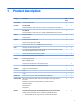
1 Product description Category Description Nontouch Touch Product Name HP Stream Notebook PC 13 √ √ Processor Intel Bay Trail-M √ √ Intel Celeron N2840 (2.16 GHz, turbo up to 2.58 GHz), 1333 MHz/1 MB L2 cache), Dual-Core Intel Braswell √ Intel Celeron N3050 (1.6 GHz, turbo up to 2.
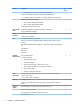
Category Description ● Nontouch Touch √ √ √ √ √ √ √ √ √ √ √ √ √ √ Realtek RT8723BE 802.11bgn 1x1 Wi-Fi + BT 4.0 Combo Adapter Support for the following dual antenna (in display assembly) WLAN module: ● Intel Dual Band Wireless-AC 3160 802.11 ac 1×1 WiFi + Bluetooth 4.
Category Description Windows 10 Home Step-up NB Entry ML Compact Nontouch Touch √ Windows 10 Home with OneDrive Entry NB ML Compact Windows 10 Home with Office365 Personal Entry NB ML Compact Windows 10 Home Value NB EM/SL Compact Windows 10 Home with OneDrive Entry NB EM/SL Compact Windows 10 Home with Office365 Personal Entry NB EM/SL Compact Windows 10 Home CH/SL Compact (CPPP) Windows 10 Home Value NB CH/SL Compact Serviceability End user replaceable parts: √ √ AC adapter SIM card 3
2 External component identification Front Item Component Description (1) Internal microphones (2) Record sound. (2) WLAN antennas (2)* Send and receive wireless signals to communicate with WLANs. (3) Mute light ● Amber: Computer sound is off. ● Off: Computer sound is on. (4) TouchPad zone Reads your finger gestures to move the pointer or activate items on the screen. NOTE: (5) Windows key The TouchPad also supports edge-swipe gestures.
Item Component Description ● When the computer is on, press the button briefly to initiate Sleep. ● When the computer is in the Sleep state, press the button briefly to exit Sleep. ● When the computer is in Hibernation, press the button briefly to exit Hibernation. CAUTION: Pressing and holding down the power button will result in the loss of unsaved information.
Item Component Description To access this document in Windows 10: Select Start, select All apps, select HP Help and Support, and then select HP Documentation. Left side Item Component Description (9) Security cable slot Attaches an optional security cable to the computer. The security cable is designed to act as a deterrent, but it may not prevent the computer from being mishandled or stolen.
Item Component Description To insert a card: Hold the card label-side up, with connectors facing the slot, insert the card into the slot, and then push in on the card until it is firmly seated. To remove a card: Press in on the card it until it pops out. (14) Power light ● On: The computer is on. ● Blinking: The computer is in the Sleep state, a power saving state. The computer shuts off power to the display and other unneeded components. ● Off: The computer is off or in Hibernation.
Labels The labels affixed to the computer provide information you may need when you troubleshoot system problems or travel internationally with the computer. IMPORTANT: Check the following locations for the labels described in this section: the bottom of the computer, inside the battery bay, under the service door, or on the back of the display. ● Service label—Provides important information to identify your computer.
3 Illustrated parts catalog NOTE: HP continually improves and changes product parts. For complete and current information on supported parts for your computer, go to http://partsurfer.hp.com, select your country or region, and then follow the on-screen instructions.
Item Component (1) Display assembly: The display assembly is spared at the subcomponent level only. For more display assembly spare part information, see Display assembly components – non-touch screen on page 12.
Item (10) Component Spare part number Equipped with an Intel Celeron N2840 processor with 2 GB system memory, 32 GB eMMC hard drive, and the Windows 8.1 Standard operating system 792785-501 Equipped with an Intel Celeron N2840 processor with 2 GB system memory, 32 GB eMMC hard drive, and Windows 7 or a non-Windows operating system 792785-001 Equipped with an Intel Celeron N3050 processor with 2 GB system memory, 32 GB eMMC hard drive, and the Windows 8.
Display assembly components – non-touch screen 12 Item Description (1) Display bezel (includes Mylar screw covers) Spare part number For use in magenta models 792768-001 For use in horizon blue models 792767-001 For use in cobalt blue models 830644-001 For use in purple models 830645-001 (2) Display bezel screw covers: The display bezel screw covers are included in all display spare part kits.
Item Description Spare part number (4) Raw display panel (includes Mylar screw covers) 792779-001 (5) Display Hinge Kit (includes left and right display hinges and Mylar screw covers) 792774-001 (6) Display panel cable (includes Mylar screw covers) (7) (8) For use in models without a touch screen and without WWAN 792771-001 For use in models without a touch screen and with WWAN 798215-001 Antenna Kit (includes wireless antenna cable, transceiver, Mylar screw covers, and screws) WLAN 792758
Display assembly components – touch screen Item Description (1) Display panel assembly, includes bezel and Mylar screw covers For use in horizon blue models 792780-001 For use in orchid magenta models 792781-001 (2) Display bezel screw covers: The display bezel screw covers are included in all display spare part kits.
Item Description Spare part number For use in touch screen models with WWAN 798216-001 (5) Display Hinge Kit (includes left and right display hinges) 792775-001 (6) Antenna Kit (includes wireless antenna cable, transceiver, Mylar screw covers, and screws) (7) WLAN 792758-001 WWAN 792757-001 Display back cover (includes Mylar screw covers and screws) For use in horizon blue models 792759-001 For use in orchid magenta models 792762-001 Miscellaneous parts Component Spare part number AC ad
Component Spare part number Rubber Feet Kit (includes bottom cover screw covers and computer feet) For use in horizon blue and orchid magenta models 792782-001 For use in cobalt blue and violet purple models 830713-001 Screw Kit 792783-001 HP 14.0 Spectrum Blue Sleeve 787585-001 HP 14.
Spare part number Description 784638-005 Intel Dual Band Wireless-AC 3160 802.11 ac 1×1 WiFi + Bluetooth 4.0 Combo Adapter 787521-005 3-cell, 37-WHr, 3.25-AHr, Li-ion battery (includes cable) 792608-005 Broadcom BCM43142 802.11 b/g/n 1x1 Wi-Fi + BT4.0 M.
18 Spare part number Description 792785-001 System board equipped with an Intel Celeron N2840 processor with 2 GB system memory, 32 GB eMMC hard drive, and the Windows 7 or non-Windows operating systems (includes thermal grease and thermal pads) 792785-501 System board equipped with an Intel Celeron N2840 processor with 2 GB system memory, 32 GB eMMC hard drive, and the Windows 8.
Spare part number Description 792791-AB1 Keyboard/top cover (does not include touchpad) for use in horizon blue models in Taiwan (includes keyboard cable) 792791-AD1 Keyboard/top cover (does not include touchpad) for use in horizon blue models in South Korea (includes keyboard cable) 792791-B31 Keyboard/top cover (does not include touchpad) for use in horizon blue models internationally (includes keyboard cable) 792791-BA1 Keyboard/top cover (does not include touchpad) for use in horizon blue model
20 Spare part number Description 792792-B31 Keyboard/top cover for use in magenta models internationally (includes keyboard cable) 792792-BA1 Keyboard/top cover for use in magenta models in Slovenia (includes keyboard cable) 792792-BB1 Keyboard/top cover for use in magenta models in Israel (includes keyboard cable) 792792-BG1 Keyboard/top cover for use in magenta models in Switzerland (includes keyboard cable) 792792-DB1 Keyboard/top cover for use in magenta models in Canada (includes keyboard c
Spare part number Description 830646-131 Keyboard/top cover with touchpad for use in cobalt blue models in Portugal (includes keyboard cable) 830646-141 Keyboard/top cover with touchpad for use in cobalt blue models in Turkey (includes keyboard cable) 830646-151 Keyboard/top cover with touchpad for use in cobalt blue models in Greece (includes keyboard cable) 830646-161 Keyboard/top cover with touchpad for use in cobalt blue models in Latin America (includes keyboard cable) 830646-171 Keyboard/to
22 Spare part number Description 830647-211 Keyboard/top cover with touchpad for use in purple models in Hungary (includes keyboard cable) 830647-251 Keyboard/top cover with touchpad for use in purple models in Russia (includes keyboard cable) 830647-261 Keyboard/top cover with touchpad for use in purple models in Bulgaria (includes keyboard cable) 830647-271 Keyboard/top cover with touchpad for use in purple models in Romania (includes keyboard cable) 830647-281 Keyboard/top cover with touchpad
Spare part number Description 836872-271 Keyboard/top cover with touchpad for use in horizon blue models in Romania (includes keyboard cable) 836872-281 Keyboard/top cover with touchpad for use in horizon blue models in Thailand (includes keyboard cable) 836872-291 Keyboard/top cover with touchpad for use in horizon blue models in Japan (includes keyboard cable) 836872-A41 Keyboard/top cover with touchpad for use in horizon blue models in Belgium (includes keyboard cable) 836872-AB1 Keyboard/top
24 Spare part number Description 836873-AB1 Keyboard/top cover with touchpad for use in orchid magenta models in Taiwan (includes keyboard cable) 836873-AD1 Keyboard/top cover with touchpad for use in orchid magenta models in South Korea (includes keyboard cable) 836873-B31 Keyboard/top cover with touchpad for use in orchid magenta models internationally (includes keyboard cable) 836873-BA1 Keyboard/top cover with touchpad for use in orchid magenta models in Slovenia (includes keyboard cable) 836
4 Removal and replacement procedures preliminary requirements Tools required You will need the following tools to complete the removal and replacement procedures: ● Flat-bladed screw driver ● Magnetic screw driver ● Phillips P0 screw driver Service considerations The following sections include some of the considerations that you must keep in mind during disassembly and assembly procedures.
Grounding guidelines Electrostatic discharge damage Electronic components are sensitive to electrostatic discharge (ESD). Circuitry design and structure determine the degree of sensitivity. Networks built into many integrated circuits provide some protection, but in many cases, ESD contains enough power to alter device parameters or melt silicon junctions. A discharge of static electricity from a finger or other conductor can destroy static-sensitive devices or microcircuitry.
Packaging and transporting guidelines Follow these grounding guidelines when packaging and transporting equipment: ● To avoid hand contact, transport products in static-safe tubes, bags, or boxes. ● Protect ESD-sensitive parts and assemblies with conductive or approved containers or packaging. ● Keep ESD-sensitive parts in their containers until the parts arrive at static-free workstations. ● Place items on a grounded surface before removing items from their containers.
Equipment guidelines Grounding equipment must include either a wrist strap or a foot strap at a grounded workstation. ● When seated, wear a wrist strap connected to a grounded system. Wrist straps are flexible straps with a minimum of one megohm ±10% resistance in the ground cords. To provide proper ground, wear a strap snugly against the skin at all times. On grounded mats with banana-plug connectors, use alligator clips to connect a wrist strap.
5 Removal and replacement procedures for Authorized Service Provider parts NOTE: Components described in this chapter should only be accessed by an authorized service provider. Accessing these parts can damage the computer or void the warranty. NOTE: Details about your computer, including model, serial number, product key, and length of warranty, are on the service tag at the bottom of your computer. See Labels on page 8 for details. NOTE: HP continually improves and changes product parts.
For use in country or region Spare part number For use in country or region Spare part number Includes touchpad; for use in orchid magenta models: For use in Belgium 836873-A41 For use in Portugal 836873-131 For use in Bulgaria 836873-261 For use in Romania 836873-271 For use in Canada 836873-DB1 For use in Russia 836873-251 For use in the Czech Republic and Slovakia 836873-FL1 For use in Saudi Arabia 836873-171 For use in Denmark, Finland, and Norway 836873-DH1 For use in Slovenia 83
For use in country or region Spare part number For use in country or region Spare part number Includes touchpad; for use in horizon blue models: For use in Belgium 836872-A41 For use in Portugal 836872-131 For use in Bulgaria 836872-261 For use in Romania 836872-271 For use in Canada 836872-DB1 For use in Russia 836872-251 For use in the Czech Republic and Slovakia 836872-FL1 For use in Saudi Arabia 836872-171 For use in Denmark, Finland, and Norway 836872-DH1 For use in Slovenia 8368
For use in country or region Spare part number For use in country or region Spare part number Includes touchpad; for use in violet purple models: For use in Belgium 830647-A41 For use in Portugal 830647-131 For use in Bulgaria 830647-261 For use in Romania 830647-271 For use in Canada 830647-DB1 For use in Russia 830647-251 For use in the Czech Republic and Slovakia 830647-FL1 For use in Saudi Arabia 830647-171 For use in Denmark, Finland, and Norway 830647-DH1 For use in Slovenia 830
5. Remove one screw cover (3) from the middle rear of the computer bottom. The screw covers and the computer rear feet are included in the Rubber Kit, spare part number 792782-001 for horizon blue and orchid magenta models or 830713-001 for cobalt blue and violet purple models. 6. Remove the 13 Phillips PM2.5×6.0 screws that secure the keyboard/top cover to the bottom cover. 7. Turn the computer right side up, with the front toward you. 8. Open the computer.
10. Disconnect the following cables from the system board: (3): Battery cable (4): Touchpad cable (5): Keyboard cable (6): Power button board cable 11. Remove the keyboard/top cover from the computer (7). Reverse this procedure to install the keyboard/top cover.
TouchPad Description Spare part number TouchPad for use in models without WWAN (includes cable) 795911-001 TouchPad for use in models with WWAN (includes cable) 792776-001 TouchPad cable 838683-001 Before removing the TouchPad, follow these steps: 1. Turn off the computer. If you are unsure whether the computer is off or in Hibernation, turn the computer on, and then shut it down through the operating system. 2.
Power button board Description Spare part number Power button board (includes cable) 792777-001 Before removing the power button board, follow these steps: 1. Turn off the computer. If you are unsure whether the computer is off or in Hibernation, turn the computer on, and then shut it down through the operating system. 2. Disconnect the power from the computer by unplugging the power cord from the computer. 3. Disconnect all external devices from the computer. 4.
WLAN module Description Spare part number Broadcom BCM43142 802.11 bgn 1x1 Wi-Fi + BT4.0 HMC Combo Adapter 753076-005 Realtek RT8723BE 802.11bgn 1x1 Wi-Fi + BT 4.0 Combo Adapter 753077-005 Intel Dual Band Wireless-AC 3160 802.11 ac 1×1 WiFi + Bluetooth 4.0 Combo Adapter 784638-005 Broadcom BCM43142 802.11 b/g/n 1x1 Wi-Fi + BT4.0 M.2 Combo Adapter 792608-005 Intel Dual Band Wireless-AC 3165 802.11 ac 1x1 WiFi + BT 4.
3. Remove the WLAN module (3) by pulling the module away from the slot at an angle. NOTE: If the WLAN antenna is not connected to the terminal on the WLAN module, a protective sleeve must be installed on the antenna connector, as shown in the following illustration. Reverse this procedure to install the WLAN module.
WWAN/GPS module Description Spare part number HP hs3110 HSPA+ Mobile Broadband Module 748599-005 HP hs3114 HSPA+ Mobile Broadband Module 748600-005 CAUTION: To prevent an unresponsive system, replace the wireless module only with a wireless module authorized for use in the computer by the governmental agency that regulates wireless devices in your country or region.
3. Remove the WWAN module (3) by pulling the module away from the slot at an angle. NOTE: If the WLAN antenna is not connected to the terminal on the WWAN module, a protective sleeve must be installed on the antenna connector, as shown in the following illustration. Reverse this procedure to install the WWAN module.
Battery Description Spare part number Battery, 3-cell, 37-WHr, 3.25-AHr, Li-ion (includes cable) 787521-005 Before removing the battery, follow these steps: 1. Shut down the computer. If you are unsure whether the computer is off or in Hibernation, turn the computer on, and then shut it down through the operating system. 2. Disconnect all external devices connected to the computer. 3.
USB/card reader board Description Spare part number USB/card reader board for use in models without WWAN (includes cable) 792778-001 USB/card reader board for use in models with WWAN (includes cable) 792769-001 Before removing the USB/card reader board, follow these steps: 1. Shut down the computer. If you are unsure whether the computer is off or in Hibernation, turn the computer on, and then shut it down through the operating system. 2. Disconnect all external devices connected to the computer.
Speakers Description Spare part number Speakers (include left and right speakers and cables) 792784-001 Before removing the speakers, follow these steps: 1. Shut down the computer. If you are unsure whether the computer is off or in Hibernation, turn the computer on, and then shut it down through the operating system. 2. Disconnect all external devices connected to the computer. 3.
Heat sink Description Spare part number Heat sink for use with Bay Trail (Celeron N2840) processors (includes thermal cloth) 792773-001 Heat sink for use with Braswell (Celeron N3050) processors (includes thermal cloth) 832476-001 Before removing the heat sink, follow these steps: 1. Shut down the computer. If you are unsure whether the computer is off or in Hibernation, turn the computer on, and then shut it down through the operating system. 2.
Reverse this procedure to install the heat sink.
System board Description Spare part number Equipped with an Intel Celeron N2840 processor with 2 GB system memory, 64 GB eMMC hard drive, and the Windows 8.
2. Remove the five Phillips PM2.0×2.0 broad head screws (1) that secure the system board to the bottom cover. 3. Lift the right side of the system board (2), and then pull the system board toward the right to remove it from the computer (3). Reverse this procedure to install the system board.
Display assembly – non-touch screen models NOTE: The display assembly is spared at the subcomponent level only. For display assembly spare part information, see the individual removal subsections. Before removing the display assembly, follow these steps: 1. Turn off the computer. If you are unsure whether the computer is off or in Hibernation, turn the computer on, and then shut it down through the operating system. 2. Disconnect the power from the computer by unplugging the power cord from the computer.
b. Remove the two Phillips PM2.0×3.0 screws (2) that secure the bezel to the display assembly. NOTE: The screw covers may be difficult to remove. If you need to replace the covers, they are available in the Rubber Kit, spare part number 792782-001 for horizon blue and orchid magenta models or 830713-001 for cobalt blue and violet purple models. c.
7. If it is necessary to replace the webcam/microphone module: a. Disconnect the webcam/microphone module cable (1) from the module. b. Detach and remove the module (2) from the display back cover. (The webcam/microphone module is attached to the display back cover with double-sided adhesive.) The webcam/microphone module is available using spare part number 793616-001 for models without a touch screen. 8.
a. Remove the four Phillips PM1.5×2.5 screws (1) that secure the display panel to the display back cover. CAUTION: Before turning the display panel upside down, make sure the work surface is clear of tools, screws, and any other foreign objects. Failure to follow this caution can result in damage to the display panel. b. Lift the top edge of the display panel (2) and swing it up and forward until it rests upside down in front of the display back cover. c.
e. Remove the display panel (3). The display panel is available using spare part number 792779-001 for models without a-touch screen. The display back cover is available using the following spare part numbers: 792760-001: Orchid magenta models 792761-001: Horizon blue models 830640-001: Cobalt blue models 830641-001: Violet purple models 9. 52 If it is necessary to replace the display hinges: a. Remove the four Phillips PM2.5×3.
c. Remove the display hinges (4). The display hinges are included in the Display Hinge Kit, spare part number 792774-001 for models without a touch screen. 10. If it is necessary to replace the display panel cable: a. Release the display panel cable from the retention clips (1) and channel built into the display back cover.
b. Remove the display panel cable (2). The display panel cable includes the webcam/microphone module cable and is available using the following spare part numbers: 792771-001: Models without a touch screen and without WWAN 798215-001: Models without a touch screen and with WWAN 11. If it is necessary to replace the WLAN antenna cable and transceiver: 54 a. Detach the antenna transceivers (1) from the display back cover.
c. Release the antenna cables from the retention clips (2) and channel built into the top edge and right side of the display back cover. The antenna cables and transceivers are included in the WLAN Antenna Kit, spare part number 792758-001 and WWAN Antenna Kit, spare part number 792757-001. Reverse this procedure to reassemble and install the display assembly.
Display assembly – touch screen models NOTE: The display assembly is spared at the subcomponent level only. For display assembly spare part information, see the individual removal subsections. Before removing the display assembly, follow these steps: 1. Turn off the computer. If you are unsure whether the computer is off or in Hibernation, turn the computer on, and then shut it down through the operating system. 2. Disconnect the power from the computer by unplugging the power cord from the computer. 3.
b. Remove the two Phillips PM2.0×3.0 screws (2) that secure the to the display assembly. NOTE: The screw covers may be difficult to remove. If you need to replace the covers, a Mylar screw cover kit is included in all display spare part kits. c. Lift the top of the rear cover upward (1), and then lift the cover from the display (2). The display rear cover is available using spare part number 792759-001 for horizon blue models and 792762-001 for orchid magenta models. 7.
b. Detach and remove the module (2) from the display back cover. (The webcam/microphone module is attached to the display back cover with double-sided adhesive.) The webcam/microphone module is available using spare part number 792793-001 for models with a touch screen. 8. 58 If it is necessary to replace the display hinges: a. Remove the four Phillips PM2.5×3.0 broad head screws (1) that secure the display hinges to the display back cover. b. Remove the two Phillips PM2.0×2.
c. Remove the display hinges (4). The display hinges are included in the Display Hinge Kit, spare part number 792775-001 for touch screen models. 9. If it is necessary to replace the display panel cable: a. Lift the Mylar tape from atop the connector on the panel (1), and then disconnect the cable from the connector (2). b. Disconnect the cable from the webcam module (3).
c. Remove the cable from the clips on the side of the display panel (4), and then remove the display cable from the display (5). The display panel cable includes the webcam/microphone module cable and is available using the following spare part numbers: 792772-001: Models with a touch screen and without WWAN 798216-001: Models with a touch screen and with WWAN 10. If it is necessary to replace the WLAN antenna cable and transceiver: 60 a. Detach the antenna transceivers (1) from the display back cover.
c. Release the antenna cables from the retention clips (2) and channel built into the top edge and right side of the display back cover. The antenna cables and transceivers are included in the WLAN Antenna Kit, spare part number 792758-001 and WWAN Antenna Kit, spare part number 792757-001. Reverse this procedure to reassemble and install the display assembly.
1. Disconnect the power connector cable (1) from the system board. 2. Release the power connector (2) from the retention clips built into the bottom cover. 3. Remove the power connector cable (3). Reverse this procedure to install the power connector cable.
6 Using Setup Utility (BIOS) in Windows 8.1 Setup Utility, or Basic Input/Output System (BIOS), controls communication between all the input and output devices on the system (such as disk drives, display, keyboard, mouse, and printer). Setup Utility (BIOS) includes settings for the types of devices installed, the startup sequence of the computer, and the amount of system and extended memory. Starting Setup Utility (BIOS) CAUTION: Use extreme care when making changes in Setup Utility (BIOS).
1. From the Start screen, type support, and then select the HP Support Assistant app. ‒ or – From the Windows desktop, click the question mark icon in the notification area, at the far right of the taskbar. 2. Click Updates and tune-ups, and then click Check for HP updates now. 3. Follow the on-screen instructions. 4. At the download area, follow these steps: a. Identify the most recent BIOS update and compare it to the BIOS version currently installed on your computer.
7 Using Setup Utility (BIOS) in Windows 10 Setup Utility, or Basic Input/Output System (BIOS), controls communication between all the input and output devices on the system (such as disk drives, display, keyboard, mouse, and printer). Setup Utility (BIOS) includes settings for the types of devices installed, the startup sequence of the computer, and the amount of system and extended memory.
Click the question mark icon in the taskbar. 2. Select My PC, and then select Specifications. – or – ▲ Use Setup Utility (BIOS). To use Setup Utility (BIOS): 1. Start Setup Utility (BIOS) (see Starting Setup Utility (BIOS) on page 65). 2. Select Main, select System Information, and then make note of the BIOS version. 3. Select Exit, select No, and then follow the on-screen instructions. To check for later BIOS versions, see Downloading a BIOS update on page 66.
4. Double-click the file that has an .exe extension (for example, filename.exe). The BIOS installation begins. 5. Complete the installation by following the on-screen instructions. NOTE: After a message on the screen reports a successful installation, you can delete the downloaded file from your hard drive.
8 Specifications Computer specifications Metric U.S. Width 33.32 cm 13.11 in Depth 22.44 cm 8.84 in Height (front to rear) 0.69 to 2.14 cm 0.27 to 0.84 in Weight (equipped with hard drive) 1.70 kg 3.75 lbs Weight (equipped with solid-state drive) 1.55 kg 3.42 lbs Tablet dimensions Input power Operating voltage and current 19.5 V dc @ 2.31 A – 45 W 19.5 V dc @ 3.
33.8-cm (13.3-in), HD display specifications Metric U.S. Active diagonal size 33.8-cm 13.3-in Resolution 1280x800 Display colors 262K Surface treatment Anti-glare Contrast ratio 300:1 (typical) Brightness 200 nits (typical) Viewing angle SVA Backlight LED Response time 5.5 ms/10.5 ms (Typ)(Tr/Td) Viewing angle 45/45/15/35 (Typ)(L/R/U/D) 33.8-cm (13.
9 Backing up, restoring, and recovering in Windows 8.1 This chapter provides information about the following processes. The information in the chapter is standard procedure for most models. ● Creating recovery media and backups ● Restoring and recovering your system For additional information, refer to the HP Support Assistant. ▲ From the Start screen, type support, and then select the HP Support Assistant app.
● Only one set of recovery media can be created. Handle these recovery tools carefully, and keep them in a safe place. ● HP Recovery Manager examines the computer and determines the required storage capacity for the media that will be required. ● To create recovery discs, your computer must have an optical drive with DVD writer capability, and you must use only high-quality blank DVD-R, DVD+R, DVD-R DL, or DVD+R DL discs.
▲ From the Start screen, type support, and then select the HP Support Assistant app. - or From the Windows desktop, click the question mark icon in the notification area, at the far right of the taskbar. ● If you need to correct a problem with a preinstalled application or driver, use the Drivers and Applications Reinstall option of HP Recovery Manager to reinstall the individual application or driver.
website. Go to http://www.hp.com/support, select your country or region, and follow the on-screen instructions. IMPORTANT: HP Recovery Manager does not automatically provide backups of your personal data. Before beginning recovery, back up any personal data you want to retain. Using HP Recovery media, you can choose from one of the following recovery options: NOTE: Only the options available for your computer display when you start the recovery process.
To change the boot order: 1. Insert the HP Recovery media. 2. Start Computer Setup: ▲ Turn on or restart the computer, quickly press esc, and then press f9 for boot options. 3. Select the optical drive or USB flash drive from which you want to boot. 4. Follow the on-screen instructions. Removing the HP Recovery partition (select models only) HP Recovery Manager software allows you to remove the HP Recovery partition to free up hard drive space.
10 Backing up, restoring, and recovering in Windows 10 This chapter provides information about the following processes. The information in the chapter is standard procedure for most products. ● Creating recovery media and backups ● Restoring and recovering your system For additional information, refer to the HP support assistant app. ▲ Type support in the taskbar search box, and then select the HP Support Assistant app. ‒ or – Click the question mark icon in the taskbar.
You can use Windows tools to create system restore points and create backups of personal information, see Using Windows tools on page 76. ● If your computer does list the Recovery partition and the Windows partition, you can use HP Recovery Manager to create recovery media after you successfully set up the computer. HP Recovery media can be used to perform system recovery if the hard drive becomes corrupted.
Restore and recovery There are several options for recovering your system. Choose the method that best matches your situation and level of expertise: IMPORTANT: ● Windows offers several options for restoring from backup, refreshing the computer, and resetting the computer to its original state. For more information see the Get started app. ▲ ● Not all methods are available on all products. Select the Start button, and then select the Get started app.
website. Go to http://www.hp.com/support, select your country or region, and follow the on-screen instructions. IMPORTANT: HP Recovery Manager does not automatically provide backups of your personal data. Before beginning recovery, back up any personal data you want to retain. Using HP Recovery media, you can choose from one of the following recovery options: NOTE: Only the options available for your computer display when you start the recovery process.
Changing the computer boot order If your computer does not restart in HP Recovery Manager, you can change the computer boot order, which is the order of devices listed in BIOS where the computer looks for startup information. You can change the selection to an optical drive or a USB flash drive. To change the boot order: IMPORTANT: For a tablet with a detachable keyboard, connect the keyboard to the keyboard dock before beginning these steps. 1. Insert the HP Recovery media. 2.
11 Using HP PC Hardware Diagnostics (UEFI) HP PC Hardware Diagnostics is a Unified Extensible Firmware Interface (UEFI) that allows you to run diagnostic tests to determine whether the computer hardware is functioning properly. The tool runs outside the operating system so that it can isolate hardware failures from issues that are caused by the operating system or other software components.
Downloading HP PC Hardware Diagnostics (UEFI) to a USB device There are two options to download HP PC Hardware Diagnostics to a USB device: Download the latest UEFI version: 1. Go to http://www.hp.com/go/techcenter/pcdiags. The HP PC Diagnostics home page is displayed. 2. In the HP PC Hardware Diagnostics section, click the Download link, and then select Run. Download any version of UEFI for a specific product: 1. Go to http://www.hp.com/support, and then select your country.
12 Power cord set requirements The wide-range input feature of the computer permits it to operate from any line voltage from 100 to 120 volts AC, or from 220 to 240 volts AC. The 3-conductor power cord set included with the computer meets the requirements for use in the country or region where the equipment is purchased. Power cord sets for use in other countries and regions must meet the requirements of the country or region where the computer is used.
Country/region Accredited agency Applicable note number South Korea EK 4 Sweden CEMKO 1 Switzerland SEV 1 Taiwan BSMI 4 The United Kingdom BSI 1 The United States UL 2 1. The flexible cord must be Type HO5VV-F, 3-conductor, 1.0-mm² conductor size. Power cord set fittings (appliance coupler and wall plug) must bear the certification mark of the agency responsible for evaluation in the country or region where it will be used. 2. The flexible cord must be Type SPT-3 or equivalent, No.
13 Recycling When a non-rechargeable or rechargeable battery has reached the end of its useful life, do not dispose of the battery in general household waste. Follow the local laws and regulations in your area for battery disposal. HP encourages customers to recycle used electronic hardware, HP original print cartridges, and rechargeable batteries. For more information about recycling programs, see the HP Web site at http://www.hp.com/recycle.
Index A AC adapter light 7 AC adapter, spare part numbers 15, 16 antenna location 4 removal 54, 60 spare part number 13, 15, 17, 55, 61 Antenna Kit, spare part number 13, 15, 17, 55, 61 audio, product description 1 audio-in jack 6 audio-out jack 6 B backups 70, 75 base enclosure, spare part number 11 battery removal 41 spare part number 10, 17, 41 BIOS determining version 63, 65 downloading an update 63, 66 starting the Setup Utility 63, 65 updating 63, 65 Bluetooth label 8 boot order changing 73, 79 bottom
keys Windows 4 L labels Bluetooth 8 regulatory 8 serial number 8 service 8 wireless certification 8 WLAN 8 left-side components 6 lights AC adapter 7 mute 4 power 7 webcam 5 M memory card reader 6 memory, product description 1 microphone location 4 product description 1 microphone jack 6 minimized image recovery 73, 78 minimized image, creating 72, 77 model name 1 mute light 4 O operating system, product description 2 optical drive product description 1 spare part number 15, 16 original system recovery 72
TouchPad zone 4 transporting guidelines 27 traveling with the computer 8 U USB 2.0 port 7 USB 3.