
Hardware Reference Guide - HP Compaq dc7800 Small Form Factor


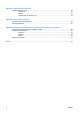
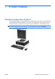
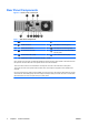
Table Of Contents
- Product Features
- Hardware Upgrades
- Serviceability Features
- Warnings and Cautions
- Using the Small Form Factor Computer in a Tower Orientation
- Unlocking the Smart Cover Lock
- Removing the Computer Access Panel
- Replacing the Computer Access Panel
- Removing the Front Bezel
- Removing Bezel Blanks
- Replacing the Front Bezel
- Installing Additional Memory
- Removing or Installing an Expansion Card
- Drive Positions
- Installing and Removing Drives
- System Board Drive Connections
- Removing an Optical Drive
- Installing an Optical Drive into the 5.25-inch Drive Bay
- Removing an External 3.5-inch Drive
- Installing a Drive into the 3.5-inch External Drive Bay
- Removing and Replacing the Primary 3.5-inch Internal SATA Hard Drive
- Removing and Replacing a Removable 3.5-inch SATA Hard Drive
- Specifications
- Battery Replacement
- External Security Devices
- Electrostatic Discharge
- Computer Operating Guidelines, Routine Care and Shipping Preparation
- Index
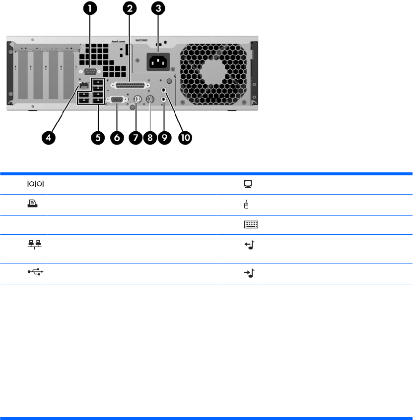
Rear Panel Components
Figure 1-4 Rear Panel Components
Table 1-3 Rear Panel Components
1 Serial Connector 6 VGA Monitor Connector
2 Parallel Connector 7 PS/2 Mouse Connector (green)
3 Power Cord Connector 8 PS/2 Keyboard Connector (purple)
4 RJ-45 Network Connector 9 Line-Out Connector for powered audio
devices (green)
5 Universal Serial Bus (USB) 10 Line-In Audio Connector (blue)
NOTE: Arrangement and number of connectors may vary by model.
If the computer has a PCI riser card assembly installed, the Serial Connector will be located on the back wall under
the expansion card slots rather than in the position shown in the above illustration.
The Line-in audio connector can be retasked as a microphone connector in the audio driver's control panel.
The monitor connector on the system board is inactive when a PCI Express x16 graphics card is installed in the
computer.
If a PCI or PCI Express x1 graphics card is installed, the connectors on the card and the system board may be used
at the same time. Some settings may need to be changed in Computer Setup to use both connectors. For information
about Boot Order, refer to the Computer Setup (F10) Utility Guide.
4 Chapter 1 Product Features ENWW