
Hardware Reference Guide - HP Compaq dc7800 Small Form Factor
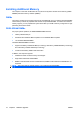
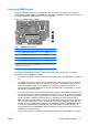
Table Of Contents
- Product Features
- Hardware Upgrades
- Serviceability Features
- Warnings and Cautions
- Using the Small Form Factor Computer in a Tower Orientation
- Unlocking the Smart Cover Lock
- Removing the Computer Access Panel
- Replacing the Computer Access Panel
- Removing the Front Bezel
- Removing Bezel Blanks
- Replacing the Front Bezel
- Installing Additional Memory
- Removing or Installing an Expansion Card
- Drive Positions
- Installing and Removing Drives
- System Board Drive Connections
- Removing an Optical Drive
- Installing an Optical Drive into the 5.25-inch Drive Bay
- Removing an External 3.5-inch Drive
- Installing a Drive into the 3.5-inch External Drive Bay
- Removing and Replacing the Primary 3.5-inch Internal SATA Hard Drive
- Removing and Replacing a Removable 3.5-inch SATA Hard Drive
- Specifications
- Battery Replacement
- External Security Devices
- Electrostatic Discharge
- Computer Operating Guidelines, Routine Care and Shipping Preparation
- Index
Populating DIMM Sockets
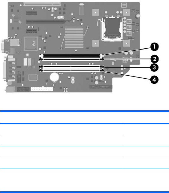
There are four DIMM sockets on the system board, with two sockets per channel. The sockets are
labeled DIMM1, DIMM2, DIMM3, and DIMM4. Sockets DIMM1 and DIMM2 operate in memory channel
A. Sockets DIMM3 and DIMM4 operate in memory channel B.
Figure 2-10 DIMM Socket Locations
Table 2-1 DIMM Socket Locations
Item Description Socket Color
1 DIMM1 socket, Channel A Black
2 DIMM2 socket, Channel A White
3 DIMM3 socket, Channel B White
4 DIMM4 socket, Channel B White
NOTE: A DIMM must occupy the black DIMM1 socket. Otherwise, the system
will display a POST error message indicating that a memory module must be
installed in the black socket.
The system will automatically operate in single channel mode, dual channel mode, or flex mode,
depending on how the DIMMs are installed.
●
The system will operate in single channel mode if the DIMM sockets are populated in one channel
only.
●
The system will operate in a higher-performing dual channel mode if the total memory capacity of
the DIMMs in Channel A is equal to the total memory capacity of the DIMMs in Channel B. The
technology and device width can vary between the channels. For example, if Channel A is
populated with two 512MB DIMMs and Channel B is populated with one 1GB DIMM, the system
will operate in dual channel mode.
●
The system will operate in flex mode if the total memory capacity of the DIMMs in Channel A is not
equal to the total memory capacity of the DIMMs in Channel B. In flex mode, the channel populated
with the least amount of memory describes the total amount of memory assigned to dual channel
and the remainder is assigned to single channel. For optimal speed, the channels should be
balanced so that the largest amount of memory is spread between the two channels. If one channel
will have more memory than the other, the larger amount should be assigned to Channel A. For
example, if you are populating the sockets with one 1GB DIMM, and three 512MB DIMMs, Channel
A should be populated with the 1GB DIMM and one 512MB DIMM, and Channel B should be
populated with the two 512MB DIMMs. With this configuration, 2GB will run as dual channel and
512MB will run as single channel.
●
In any mode, the maximum operational speed is determined by the slowest DIMM in the system.
ENWW Installing Additional Memory 19