
Hardware Reference Guide - HP Compaq dc7800 Small Form Factor
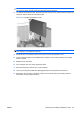
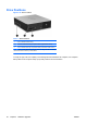
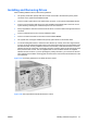
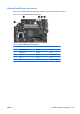
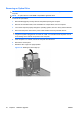
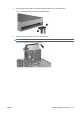
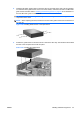
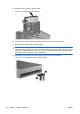
Table Of Contents
- Product Features
- Hardware Upgrades
- Serviceability Features
- Warnings and Cautions
- Using the Small Form Factor Computer in a Tower Orientation
- Unlocking the Smart Cover Lock
- Removing the Computer Access Panel
- Replacing the Computer Access Panel
- Removing the Front Bezel
- Removing Bezel Blanks
- Replacing the Front Bezel
- Installing Additional Memory
- Removing or Installing an Expansion Card
- Drive Positions
- Installing and Removing Drives
- System Board Drive Connections
- Removing an Optical Drive
- Installing an Optical Drive into the 5.25-inch Drive Bay
- Removing an External 3.5-inch Drive
- Installing a Drive into the 3.5-inch External Drive Bay
- Removing and Replacing the Primary 3.5-inch Internal SATA Hard Drive
- Removing and Replacing a Removable 3.5-inch SATA Hard Drive
- Specifications
- Battery Replacement
- External Security Devices
- Electrostatic Discharge
- Computer Operating Guidelines, Routine Care and Shipping Preparation
- Index
10. Rotate the drive cage to its upright position.
Figure 2-28 Rotating the Drive Cage Up
11. Connect the SATA data cable to the white system board connector labeled SATA1.
12. Route the data cable through the cable guides.
CAUTION: There are two cable guides that keep the data cable from being pinched by the drive
cage when raising or lowering it. One is located on the bottom side of the drive cage. The other is
located on the chassis frame under the drive cage. Ensure that the data cable is routed through
these guides before connecting it to the optical drive.
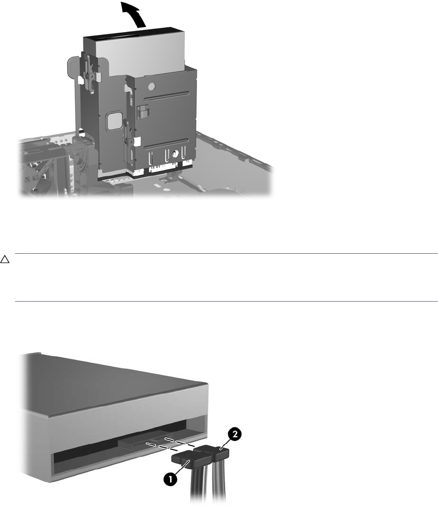
13. Connect the power cable (1) and data cable (2) to the rear of the optical drive.
Figure 2-29 Connecting the Power and Data Cables
34 Chapter 2 Hardware Upgrades ENWW