
Hardware Reference Guide - HP Compaq dc7800 Small Form Factor
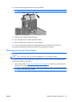
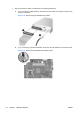
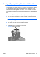
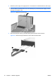
Table Of Contents
- Product Features
- Hardware Upgrades
- Serviceability Features
- Warnings and Cautions
- Using the Small Form Factor Computer in a Tower Orientation
- Unlocking the Smart Cover Lock
- Removing the Computer Access Panel
- Replacing the Computer Access Panel
- Removing the Front Bezel
- Removing Bezel Blanks
- Replacing the Front Bezel
- Installing Additional Memory
- Removing or Installing an Expansion Card
- Drive Positions
- Installing and Removing Drives
- System Board Drive Connections
- Removing an Optical Drive
- Installing an Optical Drive into the 5.25-inch Drive Bay
- Removing an External 3.5-inch Drive
- Installing a Drive into the 3.5-inch External Drive Bay
- Removing and Replacing the Primary 3.5-inch Internal SATA Hard Drive
- Removing and Replacing a Removable 3.5-inch SATA Hard Drive
- Specifications
- Battery Replacement
- External Security Devices
- Electrostatic Discharge
- Computer Operating Guidelines, Routine Care and Shipping Preparation
- Index
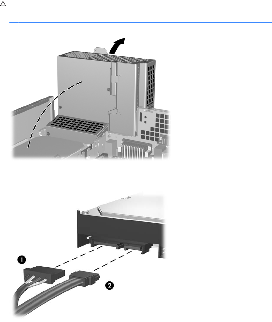
8. Rotate the power supply to its upright position. The hard drive is located beneath the power supply.
CAUTION: If the computer has a Smart Cover Lock installed next to the drive cage, carefully
route all cables around the Smart Cover Lock assembly as you raise the power supply to avoid
damage to the cables or lock.
Figure 2-36 Raising the Power Supply
9. Disconnect the power cable (1) and data cable (2) from the back of the hard drive.
Figure 2-37 Disconnecting the Hard Drive Power Cable and Data Cable
40 Chapter 2 Hardware Upgrades ENWW