Hardware Reference Guide HP ProDesk 400 G1 Small Form Factor
© Copyright 2013 Hewlett-Packard Development Company, L.P. The information contained herein is subject to change without notice. Microsoft® and Windows® are U.S. registered trademarks of Microsoft Corporation. The only warranties for HP products and services are set forth in the express warranty statements accompanying such products and services. Nothing herein should be construed as constituting an additional warranty. HP shall not be liable for technical or editorial errors or omissions contained herein.
About This Book This guide provides basic information for upgrading the HP ProDesk Business PC. WARNING! Text set off in this manner indicates that failure to follow directions could result in bodily harm or loss of life. CAUTION: Text set off in this manner indicates that failure to follow directions could result in damage to equipment or loss of information. NOTE: Text set off in this manner provides important supplemental information.
iv About This Book
Table of contents 1 Product features ............................................................................................................................................. 1 Standard configuration features ........................................................................................................... 1 Front panel components ....................................................................................................................... 2 Rear panel components .....................
Installing a security lock ..................................................................................................................... 40 Cable lock .......................................................................................................................... 40 Padlock .............................................................................................................................. 40 HP business PC security lock ............................................................
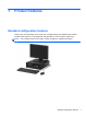
1 Product features Standard configuration features Features may vary depending on the model. For a complete listing of the hardware and software installed in the computer, run the diagnostic utility (included on some computer models only). NOTE: This computer model can be used in a tower orientation or a desktop orientation.
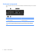
Front panel components Drive configuration may vary by model. Some models have a bezel blank covering one or more drive bays. 1 Slim Optical Drive (optional) 5 Headphone Connector 2 USB 2.0 Ports (black) 6 Dual-State Power Button 3 USB 3.0 Ports (blue) 7 Hard Drive Activity Light 4 Microphone Connector 8 3.5-inch Media Card Reader (optional) NOTE: The Power On Light is normally white when the power is on.
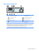
Rear panel components 1 PS/2 Mouse Connector (green) 6 Power Cord Connector 2 RJ-45 Network Connector 7 PS/2 Keyboard Connector (purple) 3 Serial Connector 8 DVI-D Monitor Connectors 4 USB 2.0 Ports (black) 9 VGA Monitor Connector 5 Line-In Audio Connector (blue) 10 Line-Out Connector for powered audio devices (green) NOTE: An optional second serial port and an optional parallel port are available from HP.
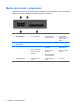
Media card reader components The media card reader is an optional device available on some models only. Refer to the following illustration and table to identify the media card reader components. No.
Serial number location Each computer has a unique serial number and a product ID number that are located on the exterior of the computer. Keep these numbers available for use when contacting customer service for assistance.
2 Hardware upgrades Serviceability features The computer includes features that make it easy to upgrade and service. No tools are needed for most of the installation procedures described in this chapter. Warnings and cautions Before performing upgrades be sure to carefully read all of the applicable instructions, cautions, and warnings in this guide.
Removing the computer access panel To access internal components, you must remove the access panel: 1. Remove/disengage any security devices that prohibit opening the computer. 2. Remove all removable media, such as compact discs or USB flash drives, from the computer. 3. Turn off the computer properly through the operating system, then turn off any external devices. 4. Disconnect the power cord from the power outlet and disconnect any external devices.
Replacing the computer access panel Place the panel on the computer (1) then slide it forward (2) and tighten the thumbscrew (3) to secure the panel in place.
Removing the front bezel 1. Remove/disengage any security devices that prohibit opening the computer. 2. Remove all removable media, such as compact discs or USB flash drives, from the computer. 3. Turn off the computer properly through the operating system, then turn off any external devices. 4. Disconnect the power cord from the power outlet and disconnect any external devices.
Removing bezel blanks On some models, there are bezel blanks covering the 3.5-inch and slim optical drive bays that need to be removed before installing a drive. To remove a bezel blank: 1. Remove the access panel and front bezel. 2. To remove a slim optical drive bezel blank, press inward on the five retaining tabs (1) and pull the blank off the front bezel (2). To remove a 3.
Replacing the front bezel Insert the four hooks on the bottom side of the bezel into the rectangular holes on the chassis (1) then rotate the top side of the bezel onto the chassis (2) and snap it into place.
Changing from desktop to tower configuration The Small Form Factor computer can be used in a tower orientation with an optional tower stand that can be purchased from HP. 1. Remove/disengage any security devices that prohibit opening the computer. 2. Remove all removable media, such as compact discs or USB flash drives, from the computer. 3. Turn off the computer properly through the operating system, then turn off any external devices. 4.
System board connections Refer to the following illustration and table to identify the system board connectors for your model. No.
Installing additional memory The computer comes with double data rate 3 synchronous dynamic random access memory (DDR3SDRAM) dual inline memory modules (DIMMs). DIMMs The memory sockets on the system board can be populated with up to two industry-standard DIMMs. These memory sockets are populated with at least one preinstalled DIMM. To achieve the maximum memory support, you can populate the system board with up to 16-GB of memory configured in a high-performing dual channel mode.
● The system will operate in flex mode if the memory capacity of the DIMM in Channel A is not equal to the memory capacity of the DIMM in Channel B. In flex mode, the channel populated with the least amount of memory describes the total amount of memory assigned to dual channel and the remainder is assigned to single channel. If one channel will have more memory than the other, the larger amount should be assigned to Channel A.
7. Open both latches of the memory module socket (1), and insert the memory module into the socket (2). NOTE: A memory module can be installed in only one way. Match the notch on the module with the tab on the memory socket. For maximum performance, populate the sockets so that the memory capacity is spread as equally as possible between Channel A and Channel B. Refer to Populating DIMM sockets on page 14 for more information. 8.
Removing or installing an expansion card The computer has three PCI Express x1 expansion slots and one PCI Express x16 expansion slot. NOTE: The PCI Express slots support only low profile cards. You can install a PCI Express x1, x4, x8, or x16 expansion card in the PCI Express x16 slot. For dual graphics card configurations, the first (primary) card must be installed in the PCI Express x16 slot. To remove, replace, or add an expansion card: 1.
9. Before installing an expansion card, remove the expansion slot cover or the existing expansion card. NOTE: Before removing an installed expansion card, disconnect any cables that may be attached to the expansion card. 18 a. If you are installing an expansion card in a vacant socket, remove the appropriate expansion slot cover on the back of the chassis. Pull the slot cover straight up then away from the inside of the chassis. b.
c. If you are removing a PCI Express x16 card, pull the retention arm on the back of the expansion socket away from the card and carefully rock the card back and forth until the connectors pull free from the socket. Pull the expansion card straight up from the socket then away from the inside of the chassis to release it from the chassis frame. Be sure not to scrape the card against the other components. 10. Store the removed card in anti-static packaging. 11.
12. To install a new expansion card, hold the card just above the expansion socket on the system board then move the card toward the rear of the chassis (1) so that the bracket on the card is aligned with the open slot on the rear of the chassis. Press the card straight down into the expansion socket on the system board (2). NOTE: When installing an expansion card, press firmly on the card so that the whole connector seats properly in the expansion card slot. 13.
18. Lock any security devices that were disengaged when the access panel was removed. 19. Reconfigure the computer, if necessary. Drive positions 1 Slim optical drive bay 2 3.5-inch internal hard drive bay 3 3.5-inch drive bay for optional drives (media card reader shown) 4 2.5-inch internal hard drive bay NOTE: The drive configuration on your computer may be different than the drive configuration shown above.
Installing and removing drives When installing drives, follow these guidelines: ● The primary Serial ATA (SATA) hard drive must be connected to the dark blue primary SATA connector on the system board labeled SATA0. ● Connect a secondary hard drive to the light blue SATA connector on the system board labeled SATA1. ● Connect an optical drive to the white SATA connector on the system board labeled SATA5. ● Connect a media card reader USB 3.0 cable with a USB 3.0 to USB 2.0 adapter to the USB 2.
CAUTION: To prevent loss of work and damage to the computer or drive: If you are inserting or removing a drive, shut down the operating system properly, turn off the computer, and unplug the power cord. Do not remove a drive while the computer is on or in standby mode. Before handling a drive, ensure that you are discharged of static electricity. While handling a drive, avoid touching the connector. For more information about preventing electrostatic damage, refer to Electrostatic discharge on page 51.
Removing a 3.5-inch device CAUTION: All removable media should be taken out of a drive before removing the drive from the computer. 1. Remove/disengage any security devices that prohibit opening the computer. 2. Remove all removable media, such as compact discs or USB flash drives, from the computer. 3. Turn off the computer properly through the operating system, then turn off any external devices. 4. Disconnect the power cord from the power outlet and disconnect any external devices.
8. Disconnect the drive cables from the rear of the drive, or, if you are removing a media card reader, disconnect the USB cable from the system board as indicated in the following illustration. 9. Press inward on the release lever at the rear of the device (1) and slide the device out of the rear of the drive bay (2).
Installing a 3.5-inch device 1. Remove/disengage any security devices that prohibit opening the computer. 2. Remove all removable media, such as compact discs or USB flash drives, from the computer. 3. Turn off the computer properly through the operating system, then turn off any external devices. 4. Disconnect the power cord from the power outlet and disconnect any external devices.
9. Rotate the drive cage to its upright position. 10. Slide the device into the drive bay, making sure to align the guide screws with the guide slots, until the device snaps into place.
11. If installing a USB 3.0 media card reader, you must use the USB 3.0 to USB 2.0 adapter and connect the adapter cable from the media card reader to the USB 2.0 connector on the system board labeled MEDIA. NOTE: Refer to System board connections on page 13 for an illustration of the system board drive connectors. 12. Rotate the drive cage back down to its normal position. CAUTION: Be careful not to pinch any cables or wires when rotating the drive cage down. 13. Replace the front bezel. 14.
16. Reconnect the power cord and any external devices, then turn on the computer. 17. Lock any security devices that were disengaged when the access panel was removed. Removing a slim optical drive CAUTION: All removable media should be taken out of a drive before removing the drive from the computer. 1. Remove/disengage any security devices that prohibit opening the computer. 2. Remove all removable media, such as compact discs or USB flash drives, from the computer. 3.
Installing a slim optical drive 1. Remove/disengage any security devices that prohibit opening the computer. 2. Remove all removable media, such as compact discs or USB flash drives, from the computer. 3. Turn off the computer properly through the operating system, then turn off any external devices. 4. Disconnect the power cord from the power outlet and disconnect any external devices.
9. Slide the optical drive through the front bezel all the way into the bay so that it locks in place (1), then connect the power and data cables to the rear of the drive (2). 10. Connect the opposite end of the data cable to the white SATA connector on the system board labeled SATA5. NOTE: Refer to System board connections on page 13 for an illustration of the system board drive connectors. 11. Replace the front bezel if it was removed.
32 5. If the computer is on a stand, remove the computer from the stand. 6. Remove the computer access panel. 7. Disconnect the power cable (1) and data cable (2) from the back of the hard drive. 8. Pull the release lever next to the rear of the hard drive outward (1). While pulling the release lever out, slide the drive back until it stops, then lift the drive up and out of the bay (2).
9. To install a hard drive, you must transfer the silver and blue isolation mounting guide screws from the old hard drive to the new hard drive. 10. Align the guide screws with the slots on the chassis drive cage, press the hard drive down into the bay, then slide it forward until it stops and locks in place.
11. Connect the power cable (1) and data cable (2) to the back of the hard drive. NOTE: The data cable for the primary hard drive must be connected to the dark blue SATA connector labeled SATA0 on the system board to avoid any hard drive performance problems. 12. Replace the access panel. 13. If the computer was on a stand, replace the stand. 14. Reconnect the power cord and turn on the computer. 15. Lock any security devices that were disengaged when the access panel was removed.
Removing a 2.5-inch hard drive 1. Remove/disengage any security devices that prohibit opening the computer. 2. Remove all removable media, such as compact discs or USB flash drives, from the computer. 3. Turn off the computer properly through the operating system, then turn off any external devices. 4. Disconnect the power cord from the power outlet and disconnect any external devices.
36 8. Disconnect the power cable (1) and data cable (2) from the back of the hard drive. 9. Pull outward on the release lever at the rear of the drive (1) then slide the drive back until it stops and pull it down and out of the drive bay (2).
Installing a 2.5-inch hard drive 1. Remove/disengage any security devices that prohibit opening the computer. 2. Remove all removable media, such as compact discs or USB flash drives, from the computer. 3. Turn off the computer properly through the operating system, then turn off any external devices. 4. Disconnect the power cord from the power outlet and disconnect any external devices.
38 8. Rotate the drive cage to its upright position. 9. Align the guide screws on the drive with the J-slots on the sides of the drive bay. Press the drive up into the drive bay then slide it forward until it locks in place.
10. Connect the power cable (1) and data cable (2) to the back of the hard drive. NOTE: If the 2.5-inch hard drive is the primary drive, connect the data cable to the dark blue SATA connector labeled SATA0 on the system board. If it is a secondary drive, connect the data cable to the light blue SATA connector on the system board labeled SATA1. 11. Rotate the drive cage back down to its normal position. CAUTION: Be careful not to pinch any cables or wires when rotating the drive cage down. 12.
Installing a security lock The security locks displayed below and on the following pages can be used to secure the computer.
HP business PC security lock 1. Fasten the security cable by looping it around a stationary object. 2. Insert the cable lock into the cable lock slot on the back of the monitor and secure the lock to the monitor by inserting the key into the key hole on the rear of the lock and rotating the key 90 degrees.
42 3. Slide the security cable through the hole in the cable lock on the rear of the monitor. 4. Use the bracket provided in the kit to secure other peripheral devices by laying the device cable across the center of the bracket (1) and inserting the security cable through one of the two holes in the bracket (2). Use the hole in the bracket that best secures the peripheral device cable.
5. Thread the keyboard and mouse cables through the computer chassis lock. 6. Unscrew the thumbscrew that secures the access panel to the chassis (1) all the way out to remove it from the access panel (2).
44 7. Screw the lock to the chassis in the thumbscrew hole using the screw provided. 8. Insert the plug end of the security cable into the lock (1) and push the button in (2) to engage the lock. Use the key provided to disengage the lock.
9. When complete, all devices in your workstation will be secured.
Front bezel security The front bezel can be locked in place by installing a security screw provided by HP. To install the security screw: 1. Remove/disengage any security devices that prohibit opening the computer. 2. Remove all removable media, such as compact discs or USB flash drives, from the computer. 3. Turn off the computer properly through the operating system, then turn off any external devices. 4. Disconnect the power cord from the power outlet and disconnect any external devices.
8. Install the security screw through the middle front bezel release tab to secure the front bezel in place. 9. Replace the access panel. 10. If the computer was on a stand, replace the stand. 11. Reconnect the power cord and turn on the computer. 12. Lock any security devices that were disengaged when the access panel was removed.
A Battery replacement The battery that comes with the computer provides power to the real-time clock. When replacing the battery, use a battery equivalent to the battery originally installed in the computer. The computer comes with a 3-volt lithium coin cell battery. WARNING! The computer contains an internal lithium manganese dioxide battery. There is a risk of fire and burns if the battery is not handled properly. To reduce the risk of personal injury: Do not attempt to recharge the battery.
7. Depending on the type of battery holder on the system board, complete the following instructions to replace the battery. Type 1 a. Lift the battery out of its holder. b. Slide the replacement battery into position, positive side up. The battery holder automatically secures the battery in the proper position. Type 2 a. To release the battery from its holder, squeeze the metal clamp that extends above one edge of the battery. When the battery pops up, lift it out (1). b.
b. Insert the new battery and position the clip back into place. NOTE: After the battery has been replaced, use the following steps to complete this procedure. 8. Replace the computer access panel. 9. Plug in the computer and turn on power to the computer. 10. Reset the date and time, your passwords, and any special system setups using Computer Setup. 11. Lock any security devices that were disengaged when the computer access panel was removed.
B Electrostatic discharge A discharge of static electricity from a finger or other conductor may damage system boards or other static-sensitive devices. This type of damage may reduce the life expectancy of the device. Preventing electrostatic damage To prevent electrostatic damage, observe the following precautions: ● Avoid hand contact by transporting and storing products in static-safe containers.
C Computer operating guidelines, routine care and shipping preparation Computer operating guidelines and routine care Follow these guidelines to properly set up and care for the computer and monitor: 52 ● Keep the computer away from excessive moisture, direct sunlight, and extremes of heat and cold. ● Operate the computer on a sturdy, level surface. Leave a 10.2-cm (4-inch) clearance on all vented sides of the computer and above the monitor to permit the required airflow.
Optical drive precautions Be sure to observe the following guidelines while operating or cleaning the optical drive. Operation ● Do not move the drive during operation. This may cause it to malfunction during reading. ● Avoid exposing the drive to sudden changes in temperature, as condensation may form inside the unit. If the temperature suddenly changes while the drive is on, wait at least one hour before you turn off the power. If you operate the unit immediately, it may malfunction while reading.
Index A access panel removal 7 replacement 8 B battery replacement 48 C computer operating guidelines 52 D DIMMs. See memory drives cable connections 22 installation 22 locations 21 E electrostatic discharge, preventing damage 51 expansion card installation 17 removal 17 F front bezel blank removal 10 removal 9 replacement 11 security 46 front panel components H hard drive (2.5-inch) installation 37 removal 35 hard drive (3.